Transcription
Self-launchingerectionmachinesfor precastconcretebridgesMarco RosignoliThe technological aspects of construction influence themodern bridge industry from the very first steps of design.Entire families of prestressed concrete bridges, such aslaunched bridges, span-by-span bridges, and balanced-cantilever bridges, take their names straight from the construction method.Construction of precast concrete bridges with spans ranging from 100 ft (30 m) to more than 600 ft (180 m) ismostly based on the use of self-launching machines. Thelaunching units are complex and delicate structures. Theyresist high loads on long spans under the same constraintsthat the obstruction to overpass exerts on the final structure. They are adaptable for reuse on different projects.They must be as light as possible, which involves designing for high stress levels in different load and supportconditions, and they are assembled and dismantled manytimes and reused by different crews.Little has been written on these machines in spite of theircost, complexity, and sophistication. The present workillustrates the main features of self-launching bridge erection machines and some lessons learned during 27 yearsof the author’s practice in the bridge industry and as anindependent design-checker of launching units.Editor’s quick pointsn Precast concrete bridges are frequently built with self-launchingerection machines.n Little has been written about these machines despite their cost,complexity, and sophistication.n This paper illustrates the main features of self-launching erection machines and presents some lessons learned.36W int e r 2 0 1 0 PCI JournalEvery construction method for precast concrete bridgeshas its own advantages and challenges. In the absence ofparticular requirements that make one solution immediately preferable to the others, the evaluation of the possiblealternatives is a difficult task. Comparisons based on thequantities of materials consider only one of the components of the construction cost of a bridge. In industrializedcountries, the cost of a bridge is more and more influencedby the processing costs of the materials, such as labor, investments for specialty equipment, delivery and assemblycosts for the equipment, and energy.
Savings in materials lower the construction cost of a bridgeonly when they are not achieved with higher technologicalcosts. In other words, greater quantities of materials do notnecessarily make a solution uneconomical, provided thatthe construction process is able to generate low labor costsand to facilitate the amortization of specialty equipment.A good balance of material costs and technological costsis the reason for the success of the incremental launchingmethod in industrialized countries.1 Compared with the useof ground falsework, bridge launching diminishes the costof labor with similar investments in equipment. Comparedwith the use of self-launching erection machines, bridgelaunching diminishes the investments in equipment withsimilar labor costs. In both cases bridge launching diminishes the technological costs, and even if the launchstresses increase the cost of prestressing, the balance ispositive and the solution is financially effective.The construction method that comes closest to bridgelaunching is segmental precasting.2 Hundreds of bridgeshave been built by segmental precasting even though theneed for avoiding joint decompression increases the cost ofprestressing. However, the investments in specialty equipment are also high, so segmental precasting is typicallyused for long bridges that allow amortization of precastingfacilities and erection machines. On shorter bridges, prefabrication is limited to the concrete girders and the deckslab is cast in place.Precast concrete segments or girders can be erected withground cranes if the piers are not tall and the area under thebridge is accessible. Sensitive environments, valleys withsteep slopes, tall piers, and inhabited areas often requireassembly by launching gantry, and in this case the technological costs increase significantly.Self-launching erection machines are complex and delicatemachines. They resist huge loads on long spans, often theweight of an entire span. Deck erection and self-launchingmust be compatible with plan and vertical curvatures of thebridge, and the most advanced units are also able to transfer their support systems to avoid the use of ground cranes.In spite of such complexity, the launching units mustalso be light. The weight governs the cost of the unit,the delivery and assembly costs, and the launch stresses.Weight limitation dictates the use of high-strength steeland designing for high stress levels under different loadand support conditions.The launching units are reused several times in differentconditions and by different crews. The units are modifiedand adapted to new work conditions, field splices are assembled and dismantled many times, and structural nodesand splices are subjected to hundreds of load reversals.The nature of loading is often highly dynamic and the unitsmay be exposed to impacts and strong wind. The supportreactions are often applied eccentrically, the support sections are often devoid of diaphragms, and most units aresupported on deformable brackets or cross beams.Mechanical and hydraulic components interact with thestructural components and often govern the stress distribution. The safety of the unit itself depends on complexinteractions among mechanical, electrical, hydraulic, andstructural components. Indeed, such design conditions arealmost inconceivable in a permanent structure subjected tosuch loads.Types and featuresof launching unitsThe industry of self-launching machines is a specialtyniche. Every unit is originally conceived for a scope, everymanufacturer has its own technological habits, every contractor has preferences and reuse expectations, and everybridge has its own technical requirements. The length ofthe bridge dictates the automation level of the equipment,and even the construction country of the unit affects someaspects of design. Nevertheless, there are not many conceptual schemes.The launching gantries for precast concrete girders comprise two parallel 3-D trusses. Two winch trolleys runalong the top chords with the girder suspended underneath, so no cross braces are typically installed betweenthe trusses. The span is relatively short; 150 ft (45 m)spans are rarely exceeded in precast concrete–girderbridges, the design load of the unit is relatively low asthe girder is just a small portion of the span, and thewinch trolleys operate far from each other as the girderis suspended at the ends. Therefore, these units are light,deformable, and often comprise transportable moduleswith tubular diagonals welded to the chords and throughpins at the field splices.A launching gantry for span-by-span erection of precastconcrete segmental box girders operates on similar spans,130 ft to 170 ft (40 m to 50 m), but the design load is muchhigher because the unit supports the entire span duringsegment assembly and the application of prestress.The most versatile overhead units comprise two parallelgirders that suspend the deck segments and support therunways for one or two winch trolleys. The girders aresupported by cross beams and are equipped with trussextensions that control overturning during launching. Thewinch trolleys operate along the entire unit so the maingirders are braced to each other only at the ends. Thegirders comprise modules joined by pins or bolts, and themodular nature of design often permits different assemblyconfigurations of chords and diagonals. These heavy workhorse units are expensive on long bridges because of theirPCI Journal Wi n t e r 201037
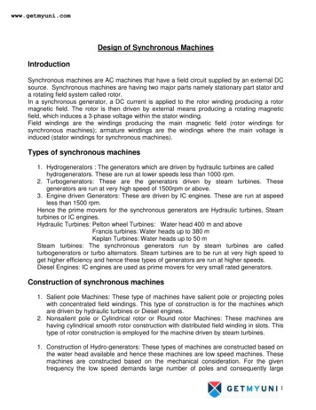
weight, the high labor demand, the complexity of operations, and the need for specific support structures.Lighter and more automated, custom-designed, singlebeam units are often preferred on long bridges. These unitsare based on one central beam; a light front extensioncontrols overturning during launching, and a rear portalframe is supported by the new span. The front end of themain girder may also be supported by a self-launchingbeam, and the connection may be pivoted to fit tight plancurvatures. These units are lighter than the twin-upperbeam units and do not require cross beams at the piers;however, they are less versatile and adaptable. These unitsare also more stable and compact and typically have fullself-launch capability.Two parallel girders are also used in the underslung units.The girders are typically equipped with front and rear extensions that control overturning and are supported on pierbrackets. The most advanced units are able to move thebrackets to the new pier. Struts from foundations are alsoused to support the unit in bridges not very high above theground. In this case, the bridge span can be longer.A cross beam running along the new span may suspendthe rear end of the unit. This diminishes the number of pierbrackets needed and shortens the unit. The front ends ofthe main girders may also be connected with a cross beamsliding along a central self-launching support beam. Theseunits are short and able to operate on tight plan curvatures.Although the depth of the main girders may cause clearance problems at the abutments or when overpassinghighways or railroads and their length is often a problem incurved bridges, the twin-lower-beam gantries for span-byspan precast concrete segmental erection are typically lessexpensive than the twin-upper-beam units.The upper-beam units for precast concrete segmentalbalanced-cantilever erection can be operated on spans thatoften exceed 350 ft (100 m). Compared with the launchingunits for span-by-span construction, the design load is lessbecause the segments are handled individually or in pairsand no entire span is suspended from the unit. Top-slabtendons in the deck resist the negative moment generatedby the segment weight, and temporary pier locks resist theload imbalance when the deck is not continuous with thepier.The design-governing load condition for the unit is typically the negative moment from the long front cantilever,so varying-depth trusses are sometimes preferred. Staycables deviated by an extension tower of the main supportframe solve the most critical cases. The load deflectionsare significant, but this is rarely a problem.The bridge itself may support lifting frames for precastconcrete segmental erection of balanced-cantilever bridges. These light units are cost-effective for short bridges andlong spans, though they typically involve longer construction duration. Compared with a launching gantry, theseunits also permit contemporaneous erection of severalhammers and erection sequences that do not require construction from abutment to abutment.Purpose-designed, multiwheel carriers with self-launchingsupport girders are used for transporting entire precastconcrete spans from the casting yard to the assembly location along the completed bridge. The span length rarelyexceeds 130 ft (40 m) because of the prohibitive designload for both the carrier and the bridge. Much longerprecast concrete spans can be handled with floating craneswhen the bridge dimensions permit amortization of suchinvestments.Launching gantries forprecast concrete girdersThe most common method for erecting precast concretegirders is with ground cranes. Cranes usually entail thesimplest and most rapid erection procedures with the minimum of investment, and the deck may be built in severalplaces at the same time. Good access is necessary alongthe entire length of the bridge to allow the cranes to bepositioned and the girders to be transported and lifted intoplace, and the bridge should be low to the ground. In thepresence of rivers, railroads, highways, or tall piers, craneerection may not be possible. Ground transportation andcrane erection of precast concrete girders are often impossible in urban areas.Ground gantries on tires or rails have been used to liftthe girders where level access is available and the deck isvery low to the ground. Less versatile than cranes, groundgantries are typically used for erecting long urban viaductsalong existing roads. Paired gantries may be necessaryfor the longest girders to limit the negative moment fromlong-end cantilevers.The use of a launching gantry often solves erection difficulties. A launching gantry for precast concrete girdersis a light modular structure comprising two parallel trusseswith triangular cross sections. The truss length is about2.3 times the standard bridge span (Fig. 1). Light bracedframes support the trusses at the piers and allow the longitudinal and transverse movements necessary to place thegirders with the due eccentricity and to launch the gantryalong curved alignments. The gantry operates without anycontact with the deck so the girders for many spans can beplaced before casting the deck slab.Two winch trolleys run along the upper chords of the gantry and lodge two winches each. The main winch suspends38W int e r 2 0 1 0 PCI Journal38
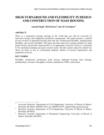
the girder, and a smaller translation winch acting on anendless ring cable moves the trolley longitudinally alongthe gantry. The endless ring cable is anchored to the opposite ends of the unit and is kept in tension by lever counterweights. A third trolley often carries an electric generatorthat feeds gantry operations. Motorized wheels can alsobe used for translation. Vertical hydraulic cylinders mayreplace the main winches when the girders are deliveredalong the completed deck.The gantry operates in one of two ways depending on howthe girders are delivered. If the girders are delivered at theground level, the gantry raises them to the deck level andplaces them onto the bearings. If the girders are deliveredat the abutment, the gantry is moved back to the abutmentand the winch trolleys are placed at the rear end of the unit.The front trolley lifts the front end of the girder and movesit forward along the unit with the rear end supported onthe ground transportation unit. When the rear end of thegirder reaches the rear winch trolley, the latter picks it upto release the ground transportation unit.The longitudinal movement of the gantry is a two-phaseprocess. Initially, the gantry is anchored to a pier and thewinch trolleys move the girder one span ahead. Then thewinch trolleys are anchored to the pier and their translationsystems launch the trusses to the next span. This sequencecan be repeated many times so that when the girders aredelivered at the abutment, the gantry can place them several spans ahead. When the bridge is long, moving the gantryover many spans slows down the erection and it may befaster to cast the deck slab as soon as the girders are placedand to deliver the next girders along the completed bridge.Figure 1. This light gantry is used for precast concrete girders. Photographcourtesy of Comtec.The typical support block for the main trusses comprises alower group of rolls or skids that move transversely alongthe support cross beam and an upper group of rolls thatsupport the bottom chord of the truss. A transverse pinconnects the two groups of rolls and allows the upper rollsto follow the rotations of the main trusses and the gradient of the launch plane. Some support blocks are equippedwith lock systems for the main trusses to avoid involuntarymovements of the unit. Most bridges have a longitudinal grade and the gantries are supported on low-frictioninclined planes, so the lock systems are critical for thestability of the unit and safety of operations.The launching gantries for precast concrete girders arerelatively inexpensive and easily adaptable in both lengthand spacing of the main trusses. They are flexible, sowedge sledges are necessary at the ends of the trusses torecover the elastic deflection during launching. These unitsare able to cope with variations in span length and deckgeometry, and because they are located above the deck,they are generally unaffected by ground-level constraintsand the plan curvature of the bridge.Launching gantriesfor span-by-span erectionof precast concretesegmental box girders span-by-span assemblySupport frames anchored to the pier caps hold a rail forthe lateral movements of the unit. The cross beam of thesupport frames typically comprises two I shapes connectedby horizontal bracing and diaphragms. Box girders are alsoused in light applications. The cross beams have lateraloverhangs to shift the gantry laterally for the placement ofthe edge girders and to launch the unit when the bridge iscurved in plan (Fig. 2). The support legs of the pier framesare located so as not to interfere with the girders (Fig. 1).They are adjustable (typically, hydraulic cylinders forgeometry adjustment and screw legs for the structural support) to set the transverse rail horizontal when the pier capis inclined. balanced-cantilever assembly progressive placement with the help of temporarystays or propsThree different techniques can be used for erecting a precast segmental box girder:With the span-by-span method, all of the segments for aspan are positioned before the prestressing tendons areinstalled, and the complete span is lowered onto the bearings. The balanced-cantilever method involves erectingthe segments as a pair of cantilevers about each pier, andthe segments are prestressed with deck slab tendons thatcross the entire hammer. With the progressive placement, alifting frame or ground crane raises and places the seg-PCI Journal Wi n t e r 201039
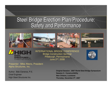
Figure 2. The edge girder is being placed. Photograph courtesy of Comtec.ments in one direction from the starting point, passing overthe piers in the process. The balanced-cantilever methodis mostly used on long spans while long viaducts withshorter spans are better suited to the span-by-span method.Progressive placement is rarely adopted.Span-by-span erection is used for both simply supportedspans and continuous superstructures. The adjacent spansof continuous bridges are joined together with in-placestitches that avoid propagation of the geometry tolerances ofshort-line segmental match-casting. After the closure pourhas hardened, continuity prestressing tendons are installedand tensioned. With span-by-span erection and epoxy joints,a typical 130 ft (40 m) span is usually erected every two orthree days. With a twin-lower-beam gantry and dry joints, anerection rate of up to one span per day is achievable.Span-by-span erection is typically used for spans shorterthan 160 ft (48 m). For longer spans, balanced-cantilevererection is often more cost-effective because of the lowercost of the gantry. Progressive placement is usually themost time-consuming erection technique because of thesingle work location; however, the specialty equipment canbe particularly inexpensive, especially when ground cranescan erect the segments along the entire length of the bridge.Upper- or lower-beam gantries are used in the span-byspan erection to support a complete span of segments,which are pulled together by prestressing bars duringgluing of the joints and then by the permanent tendons.The gantry then releases the span onto the bearings andlaunches itself forward to erect the next span.40W int e r 2 0 1 0 PCI JournalA typical twin-upper-beam gantry comprises two parallel trusses or box girders supported on cross beams. Thetruss units are preferred in high-wind regions and areoften lighter, while the box-girder units are more stableand solid. The twin-upper-beam units are easily adaptableto different span lengths, and they are able to cope withvariations in deck geometry. Because the main girders arelocated above the deck, these units are less affected byground constraints; however, they are more complex todesign, assemble, and operate and the units are slower inerecting the segments than an underslung gantry.Overturning during launching is typically controlled withextension trusses applied to the main girders. The totallength of the unit thus becomes about 2.3 times the standard span of the bridge, but this is rarely a problem withoverhead units. Cross beams anchored to the piers support the main girders with saddles that permit longitudinallaunching and lateral movements of the unit. The supportlegs of the cross beams are adjustable to ensure that theframe is level. Hydraulic cylinders are used to adjust theelevation, and safety ring nuts lock the cylinders duringoperation and launching. The cross beams are anchored tothe pier cap with prestressing bars that resist uplift forces.The cross beams have lateral overhangs to set the gantrywith the appropriate eccentricity (Fig. 3) and to launch theunit on curved spans, so significant uplift forces may arisein the anchor systems.The support rollers comprise a lower group of transverserolls, which are supported on the cross beam, and anupper group of longitudinal rolls that support the bottom
Figure 3. This shows a twin-upper-beam gantry with support cross beams. Photograph courtesy of NRS.chord. A transverse pin between the two roll assembliesmakes the support adaptable to rotations in the main girders and to launching onto grades. Some support blockslodge longitudinal lock systems for the unit, and all thesupport cross beams are typically equipped with transverse lock systems.The overhead gantries operate in one of two ways depending on how the deck segments are delivered. If the segments are delivered along the completed deck, a winchtrolley picks them up at the rear end of the gantry, movesthem over the span until reaching the assembly location,and lowers them down to the deck level. If the segmentsare delivered at the ground level, the winch trolley raisesthem up to the deck level. Hangers are used to align andhold the segments in position during assembly. Afterreaching the assembly location, the segments are hungfrom the main girders and the winch trolley is released fora new cycle. To avoid interference with the hangers of thepreviously placed segments, the segments are moved outwith the long side in the longitudinal plane of the bridge.The segments are rotated 90 deg just before suspensionwith a special hook that is able to hydraulically turn thesegment.Typically, all of the segments for the span are suspendedfrom the gantry before the joints are glued so that no additional truss deflections can occur. Epoxy is applied togroups of segments that are then pressed together withtemporary clamping bars. The permanent tendons areusually tensioned from a stressing platform attached to thefront segment.The lightest gantries may be launched with winches, suchas those units for precast concrete girders. Typically, however, long-stroke hydraulic cylinders lodged into the support saddles and acting against racks anchored to the maingirders are used to push the unit forward. Twin cylindersare often used so that one cylinder anchors the unit duringrepositioning of the adjacent cylinder. Figure 4 shows thelaunch cylinders of a twin-lower-beam gantry in the raisedconfiguration for segment assembly. Lowering the supportjacks releases the span onto the launch bearings in oneoperation.Single-upper-beam gantries may also be used for span-byspan precast concrete segmental erection. In these units,the carrying structure is a longitudinal girder that is supported at the front pier of the span to be erected and at therear pier (in the case of simply supported spans) or on thefront overhang of the completed deck (in the case of a continuous bridge). The main girder may comprise two bracedtrusses or plate girders, or it may be a triangular truss withone upper chord and two bottom chords. A winch trolleyruns along the unit and moves the deck segments to theassembly locations.PCI Journal Wi n t e r 201041
times equipped with prestressing or stay cables, thoughthis complicates and slows the operations and increaseslabor demand. Truss gantries are preferred in this case forbetter control of buckling and simpler structural nodes atthe anchor points of stay cables.Figure 4. The launch cylinders of a twin-lower-beam gantry are shown in theraised configuration for segment assembly.A light front extension typically controls overturning during launching. The rear end of the unit is supported by thecompleted span. No rear nose is necessary, so these unitsare shorter than a typical twin-upper-beam gantry and aremore adaptable to curvatures in the bridge. The main girderis stiffer than two parallel trusses, and its support systemsare also stiffer.Lateral bracing connects the trusses or plate girdersalong their entire length (Fig. 5). Lateral bracing typically includes cross beams between the flanges or chords,connections designed to minimize displacement-inducedfatigue, and sufficient flexural stiffness to resist vibrationstresses. Cross frames connected to the flanges or chords atthe same locations of lateral bracing distribute torsion andprovide transverse rigidity. Connections are often designedto develop member strength.The gantry supports an entire span, so the main girder isheavily stressed. The units for the heaviest spans are some-Special support devices are necessary to launch the unitwhen the front support frame is integral with the maingirder. Launching is typically achieved by friction, takingadvantage of the support reaction that the main girderapplies to the launcher. Figure 6 shows a typical frictionlauncher assembled onto a support tower. A support boxis located underneath each bottom flange or chord of themain girder. A hydraulic cylinder moves the box longitudinally along the low-friction surface of a pivoted arm, andtwo jacks at the opposite ends of the arm lift and lower themain girder. The working sequence is as follows:1.The vertical jacks lower the unit onto the supportboxes.2.The thrust cylinders push the support boxes forward,and the thrust force is transferred to the main girder byfriction.3.When the launch cylinders reach the limit stop, thejacks lift the unit and the support boxes may returnidle to the initial position to start this cycle again.The friction launchers are typically pinned to the supporttowers to allow rotations when launching along curvedalignments. Low-friction surfaces between the supporttower and the base frame also allow lateral shifting (Fig. 6).These geometry-control systems are equipped with slidingclamps so that the entire assembly can be suspended fromthe main girder (Fig. 7). Figure 7 shows the two frictionlaunchers of the unit suspended from the front overhang.The rear support of the gantry is an adjustable frame thatruns along the completed span. Horizontal hydraulic cylinders control the transverse alignment of the frame whenlaunching along curved spans, and vertical cylinders control the support reaction that the frame transfers to the deck.Upon completion of span erection, the rear launcher ismoved backward to the front pier or overhang. In the firstphase of launching, the unit is typically supported at therear launcher and at the rear support frame. When the frontend of the unit reaches the next pier, the pier-cap segmentand the front launcher are positioned for launch completion. A front support leg typically controls overturningduring this operation. At the end of launching, the twolaunchers are suspended from the front overhang and anew span can be erected with the unit supported at themain frame and the rear portal frame.Figure 5. Lateral bracing of a single-upper-beam gantry in a movable scaffoldingsystem configuration connects the plate girders along their entire length.42W int e r 2 0 1 0 PCI JournalRefined single-upper-beam machines have been designedfor erecting precast concrete segmental box girders with
tight plan curvatures. In the unit of Fig. 8, the winch trolleyis suspended from the bottom flanges and the deck segments are delivered on the ground or along the completeddeck through the rear support frame. To accommodatetight plan curvatures, the gantry comprises two elements:a rear main girder and a front support beam. A turntablewith hydraulic controls for translation and vertical andhorizontal rotations connects the main girder to the supportbeam. During launching, the turntable pulls the main girderalong the support beam. When the front support frame hasreached the front pier, the support beam is launched forward to clear the area under the main girder for assemblyof the new span.Many precast concrete segmental bridges have also beenerected with underslung gantries. These units are positioned beneath the deck with the two trusses or box girderson opposite sides of the pier, and the gantry supports thesegments under the lateral overhangs. The unit is typicallysupported on pier brackets or props from foundations.When the deck is low to the ground, midspan props may beused to increase the operating span of the unit.When overturning is controlled with front and rear extensions, the length of the unit is more than twice the typicalspan length. A central front launching beam may be usedin curved bridges to support the main girders in combination with a rear support frame running on the completeddeck. This type of gantry is a telescopic assembly of acentral support beam and two lateral girders that supportthe segments. This solution requires a particular design ofthe pier head to create the launch clearance for the supportbeam.The segments are placed onto the gantry with a crane orlifting frame. When the segments are delivered through thecompleted deck, the lifter is placed at the rear end of thegantry. When the segments are delivered on the ground, thecrane is placed at the front end of the gantry. The segmentsare placed onto the gantry close to the lifter and are movedalong the gantry to the assembly position with rollers.Upon completion of assembly and application of prestress,the gantry lowers the span onto the bearings.Figure 6. A friction launcher is assembled onto a support tower.ing noses after erecting the f
Self-launching erection machines are complex and delicate machines. They resist huge loads on long spans, often the weight of an entire span. Deck erection and self-launching . weight, the high labor demand, the complexity of opera-tions, and the need for specific support structu