Transcription
INSTALLATION MANUAL
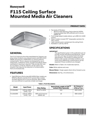
Storage and Handling Ceiling panels must be kept clean, dry, and protected from the elements. Remove the panels from the cartons 24 hoursbefore installation to acclimatize to interior conditions. The installation site must be free from debris and dust. Irrespective of varying temperature and humidity recommendations which vary from product to product, all products mustbe stored in a interior space and not exterior space.Mineral FibreMetal & Soft fibreFRAGILEUP Opening a grid cartonStep 1:Identify dotted lineStep 2: Cut along dotted lineStep 3: Open from one sideStep 4: Ready to removeOpening a mineral fibre tile cartonArmstrong recommends that RH 99 & 90 products are to be opened and left to acclimatize for 24 hours before fixing.This makes the tiles dry and hard. Wrong box opening method2 Step 1: Cut the polythene film Step 2: Remove the polythene Step 3: Remove the tilefilm
IndexSection I: Standard Modular Ceiling Installation and Maintenance9 Step Ceiling Installation Procedure.4MetalWorks Tiles Cutting Procedure.17Section II: Components, Safety and ToolsCeiling Components.18Safety & Precautions.19Tools.21Section III: AppendixMaintenance.22Check list for Lay-in Ceiling Installation.23Glossary.39Note: The installation procedure for MetalWorks lay-in ceiling systems is similar to that for Mineral fibre ceilingsystems, except for the procedure required to cut MetalWorks tiles, which is given on page 17.3
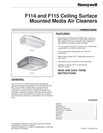
9 Step Ceiling Installation Procedure132BMin 100 mmAMA1000600800 450 mmB1. Planning grid layout42. Mark perimeter trim lines3. Installing perimeter trims (Wall angle)65Max600 mm1200 mm1200 mm1200 mm4. Mark hanger positions6. Installation of Main Runners5. Installation of hangers798A /BA /B7. Cross Tees installation8. Installation of field and service tiles9. Measure and cutborder tilesImportant Note: Please read Section II: Components, Safety and Tools before commencement of ceiling installation.Sketch showing basic ceiling layout and placing of the 0m600mmm0m60m0m60mm600m0m601. Main Runner2. 1200mm Cross Tee3. 600mm Cross Tee4. Suspension System5. Wall Angle6. Tile
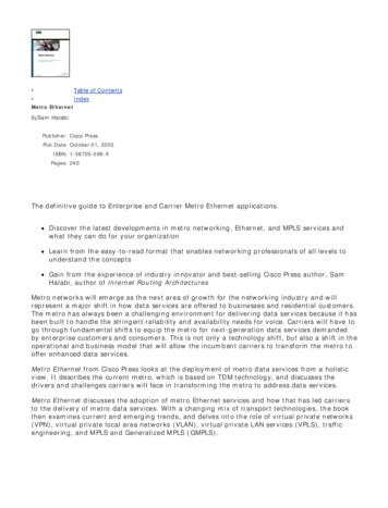
Step 1: Planning Grid LayoutA) Wall to wall (with field and border tiles)This is one of the most important step before commencement of actual ceiling installation. Here grid layout is arrived bytaking into consideration room dimensions {length(l) x breadth(b) x height(h)}Points to remember: In practical conditions, often the room dimensions are not exactly square in dimensions.Thumb rule: Armstrong recommends to have border cut tiles greater than half the size of the ceiling tiles on allfour sides of the wall.Refer layout for diagram 1.1Ceiling Module: 600mm x 600mmRoom dimensions: 4320mm x 2700mm (l x b)Tiles calculation l: 4320mm 7 full tiles 2 x 60mm cut tiles ( incorrect calculation) 6 full tiles 2 x 360mm cut tiles ( correct calculation)Note: Please follow the above method for breadth border cut tile calculation.Wrong Method600mm450mm360mm Main Runner Connection250mmDiagram 1.0Main Runner1200mm Cross Tee600mm Cross TeeSuspension System(Hanger Wire)Service TilesField TilesBorder TilesWalls360mm1335mm120mm1335mmMain Runner 5mm600mm600mm 1200mm250mm600mm2700mm600mmCorrect Method450mm2700mmDiagram 1.1TOINTEPYKE TO NOBorder tiles shouldbe more than 300mm5
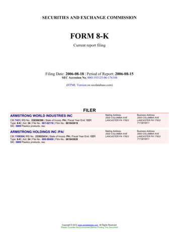
Step 1: Planning Grid LayoutB) With Plaster bulk heads (full tiles module)Plaster bulk heads are used to design spaces to enclose full border tiles and enclose vertical grilles for HVAC.Below mention is a simple thumb rule to calculate ceiling installation with full border tiles.(A-T/2)FATDBulkheadn Number of panelF Full tile sizeT T-grid face widthA Distace between angle moulding face and bulkheadD Distance between bulkheadD nF (2A-T)Diagram 1.2Assuming, we are developing a module of 3600mm X 3600 mm i.e 6 tiles X 6 tiles within the plaster bulk head. Most often one would take an internal measurement, between the bulkheads of 3600mm X 3600mm. But thisis an incorrect method and while doing final installation, you may end up cutting the border tiles on all the four sides. Thumb rule: Add two sides wall angle width and deduct the width of the main tee to get the extra length. Assume we use 19mm wall angle and 24mm grid facing, then the overall length should be 3614mm to achieve the full tilevisual.Thumb rule calculationWall AngleDescriptionWall MoldingShadow MoldingSteel Angle Face WidthSize (mm)15mm24mm19x19x3000mmAdd 23mmAdd 14mm19x7x7x14x3000mm Add 13mmAdd 04mmWall Molding32x24x3000mmAdd 33mmAdd 24mmAluminium WallMolding19x25x3000mmAdd 35mmAdd 26mmWall Molding22x22x3000mmAdd 29mmAdd 20mmNote: The addition to the original length or breadth will avoid the need for border tiles.TOINTEPYKE TO NOArriving atbulkhead dimensionscritical for full tilesmodule6
Step 2: Mark Perimeter Trim Lines Measuring the ceiling height is the most crucial stage before commencing installation. The minimum plenum height from the ceiling slab should not be less than 100mm for lay-in system. The reference ceiling level should be established by the main contractor with the help of all other services vendorslike light fixtures, Air condition grilles, sprinklers, speakers etc. Using a plumb mark as a reference point, place line laser leveller on it. Then with the help of laser point, mark wall anglelevel on all sides of the room.TOINTEPYKE TO NOLine laser levellersaves time andensures precision7
Step 3: Installing Perimeter Trims (Wall Angle) The marking with the help of line laser leveller has to be done above the wall angle level on all the walls. Post marking used hand drill to installed the wall angle. The first and the last fasteners on wall angle should be installed at 150mm from the wall (see for details recommendedfastener on page no.19). Subsequent fasteners to be installed at 450mm spacing in between.TOINTEPYKE TO NO 150mm 450mmSecure to wall at450mm maximumcentres At the corners of the room, the conjunction area of wall angle is recommended to be miter cut for a clean finish. Bottom view Bottom view Top view8 Top view
Step 4: Mark Hanger Positions The hanger on the main runner shoud be placed at or within 600mm distance from the wall angle(450mm is recommended in case of heavier ceilings) and then subsequently at 1200mm centres.1200mm600mmTOINTEPYKE TO NO450mm360mm450mm2985mm600mmHanger positionmust be within600mm distancefrom the wallMain Runner Connection4320mmxxxMain tee connectionSuspension System(Hanger Wire)360mm1335mmMain RunnerxWalls2700mmDiagram 1.0 There should also be a hanger within 150mm of any main runner to runner connection.1200mm600mm450mmMain Runner1200mm Cross Tee600mm Cross TeeSuspension System(Hanger Wire)Service TilesField TilesBorder TilesWalls360mm1335mmMain Runner m450mm2700mmDiagram 1.1TOINTEPYKE TO NOHanger position mustbe within 150mmdistance of everymain runnerconnection9
Step 5: Installation of Hangers Use a rotary hammer machine to drill and install the hangers from the concrete ceiling slab.300mm045 01.80mtr.45300mmTOINTEPYKE TO NOUse countersplaying wires ifhanger length is 1.8mtr.WIRES PLUMB:MAX. SLOPE 1 IN 1.8MTR IN ANY PLANEIF MORE, USE COUNTER SPLAYING WIRESDiagram 1.3 If the hanger wire plumb more than 1.8 meter then use counter splaying wire refer above diagram. In counter splaying, two hanger wires from the structural slab form an angle of 450 near the main runners. Onesuspension countering another in the same plane. Install the hanger wire as per the position in the diagram 1.1. Suspension hanger wire shall be pre-straightened with minimum 2.5mm dia (# 12 Gauge). Insert wire of required length into hanger wire hole and encircle the wire 3 times within 75mm.Installation under AC duct If AC duct is greater than 1200mm in length, then ensure you suspend a separate bracket under the duct and from it, ahanger-wire can be suspended for ceiling installation.Ceiling SoffitTOINTEPYKE TO NO1400mmDuct Section90Ensure suspensionfree from servicesSuspension100Duct Suspension1200mmCeiling TileDiagram 1.4ThreadedRod/Hanger Wire/Vertical SupportSlotted Bar / Main teefor Suspending theCeilingTypical Sectional Sketch - Below Duct Suspension (Trapeze Installation)10
Step 6: Installation of Main Runners Run a string line the length of your first main runner offset to the edge flange. This will help to keep the main runner setdistance of the wall.TOINTEPYKE TO NOMain runnerUse only aviationsnip for precisecutting of mainrunnersCross teeString Line Cut the main runner to the length with respect to the border tile, so that the rout hole on the adjacent main runnermatches. E.g. As per diagram 1.5, the main runner will be cut at 15 mm using an aviation snip cutter to ensure that the rout holewill be at a distance of 360 mm.Rout hole360mmCut main beam so that arout lines up at bordertee locationDiagram 1.5 Cut the main runner at inclination of 30-45 degree to avoid obstruction of protruding screws.Armstrong provides following grids.GridsRout HoleInterval (mm)Distance of 1stRout Hole fromthe End Clip(mm)Prelude 32150mm75mmPrelude 35100mm75mmPrelude 43100mm50mmSuprafine 32150mm75mmSuprafine 43100mm50mmSilhouette 38600mm300mmSelect 32600mm300mm11
The first main runner should be less than 600mm from the perimeter wall. The distance between next main runner shall be at 1200 mm maximum. You may incline the first suspension system slightly to push the main runner in one direction so that the rout holesare better aligned. Hangers with hook clip options can be inserted in alternate direction on the main runner for better stability. Border cross tees should be more than 300mm but less than 600mm in length. Cut the excess portion or bend the wire as shown in the picture. Insert an additional row of main runner or alternatively suspend allborder cross tees longer than 600mm.12INTEOYP TKE TO NOMain runnerand border crosstee should not bemore than 600mmdistance fromthe wall
Step 7: Cross Tees Installation As per diagram 1.1 (page 5) install border cross tee 448mm (2mm allowance is kept for cross tee to rest on thewall angle easily). Install border cross tees temporarily to the wall molding using a clamp to keep them intact.Clamp Install two 1200 cross tees between the two main runners at an distance of 600mm. A click sound confirms that the cross tee has been properly locked into the main runner.TOINTEPYKE TO NOClick soundconfirms crosstee locked Measurements should be taken diagonally in the 600 x 1200mm module. Both the diagonals must be of the same length.X1200600Yba600 In case of any deviation in the measurement of the diagonals gently tap at the corners. This will ensure that the entire ceiling grids will be in a perfect shape.Main runnerMAINRUNNER(a-b) shold be less than1mm for 600x600mm tilesand less than 2mm for600x1200mm tiles.Diagram 1.6Cross teeString Line Once the system is in perfect shape run another string line at the first cross tee slot on the main runner to the far adjacentwall angle using the first two square mains as the guide. This ensure the tee rout holes on all the main runners stay inaligned.13
Step 8: Installation of Field and Service Tiles Check the level once again using line laser leveller. Ensure that all the services placed on service tiles are tested and confirmed by the principal contractor. Only after that,laying of field tiles can be commenced. While installing down lighters, spotlights, sprinklers, speakers, smoke detectors etc. 6mm plywood (pattress backingmust be placed on the grid).TOINTEPYKE TO NOPatress a must forinstalling servicesto avoid directloading onceiling systemPatress backing It is mandatory to independently suspend modular light fixtures. GI wire min 2.5 mm is recommended to suspend the lightfixtures. Hook Clips and Chains are not recommended. 14
Step 9: Measure and Cut Border Tiles Measure the border tile size. Mark the border size on back side of the tile. Use a grid or a steel ruler (2 ft long) to mark and cut the border tiles. While installing, slightly tilt the tile and gently rest it on the main runner and adjacent cross tee and wall angle.TOINTEPYKE TO NOHow to make tegular and curved shape edges on border tileChalk the cutedges ofborder tilesA) Tegular edge Use a sharp knife. Lay the tile on a smooth surface. Make vertical cut into face of the tile. Make horizontal cut to form tegular edge.15
Installing end cap in tegular edge installation End cap ensures that a tegular look is achieved at the border. Lift the steel angle and insert the end cap between the tee and the wall angle. End cap ensures aligned level difference at the perimeter.B) Curved shape (square edge) Use a sharp knife. Lay the tile on a smooth surface. Use a cardboard or plywood template. Mark outline of the template. Use a sharp knife to cut through.16
Metalworks Tiles Cutting Procedure Measure and mark the line on the metal tile using a pencil. The bent edge of tile should be cut using aviation snip. Use a shear machine to cut the face of the metal tile.TOINTEPYKE TO NOCut the metal tileedge using aviationsnip and only thenuse shear machine
Armstrong recommends that RH 99 & 90 products are to be opened and left to acclimatize for 24 hours before fixing. This makes the tiles dry and hard. Opening a grid carton Step 3: Remove the tile Step 4: Ready to remove Step 2: Remove the polythene film Step 3: Open from one side Wrong box opening method Step 1:Identify dotted line