Transcription
UserGuideEclipse ICS 1008E/1016EIntercom PanelsUser GuidePart Number:399G222 Rev ADate: April 10, 2017Page 1
Document ReferenceICS 1008E/1016E Intercom PanelsPart Number: 399G222 Revision: ALegal DisclaimersCopyright 2017 HME Clear-Com Ltd.All rights reserved.Clear-Com and the Clear-Com logo are trademarks or registered trademarks of HMElectronics, Inc.The software described in this document is furnished under a license agreement and maybe used only in accordance with the terms of the agreement.The product described in this document is distributed under licenses restricting its use,copying, distribution, and decompilation / reverse engineering. No part of this documentmay be reproduced in any form by any means without prior written authorization of ClearCom, an HME Company.Clear-Com Offices are located in California, USA; Cambridge, UK; Dubai, UAE; Montreal,Canada; and Beijing, China. Specific addresses and contact information can be found onClear-Com’s corporate website:www.clearcom.comClear-Com ContactsAmericas and Asia-Pacific HeadquartersCalifornia, United StatesTel: 1 510 337 6600Email: CustomerServicesUS@clearcom.comEurope, Middle East, and Africa HeadquartersCambridge, United KingdomTel: 44 1223 815000Email: CustomerServicesEMEA@clearcom.comChina OfficeBeijing Representative OfficeBeijing, P.R.ChinaTel: 8610 65811360/65815577Page 2
1234Operation .61.1Introduction . 61.2Description . 6Installation .172.1Equipment mounting . 172.2Wiring . 172.3Mains ac power. 182.4Adjustments . 192.5Configuration . 20Maintenance .213.1Panel reset . 213.2Troubleshooting . 213.3Servicing . 233.4Service items for ICS-1016E . 24Specifications .264.1ICS-1008E/1016E panel. 265Glossary .286Warranty .326.17Limited warranty . 32FCC Compliance .36Page 3
Safety instructionsFor your safety, it is important to read and follow these instructions beforeoperating an ICS-1008E/1016E intercom panel.WARNING: To reduce the risk of fire or electric shock, do not expose an ICS1008E/1016E intercom panel to rain or moisture. Do not operate an ICS-1008E/1016Eintercom panel near water, or place objects containing liquid on it. Do not expose anICS-1008E/1016E intercom panel to splashing or dripping water.(2)For proper ventilation, make sure ventilation openings are not blocked.Install the ICS-1008E/1016E according to the directions in the InstallationChapter of this manual.(3)Do not install an ICS-1008E/1016E intercom panel near a heat source suchas a radiator, heat register, stove, or other apparatus (including amplifiers) thatproduces heat. Do not place naked flame sources such as candles on or near apanel.(4)Do not defeat the safety purpose of the polarized or grounding-type plug. Apolarized plug has two blades, with one blade wider than the other. A groundingtype plug has two blades and a third grounding prong. The wide blade or the thirdprong is provided for your safety. If the provided plug does not fit into youroutlet, consult an electrician for replacement of the obsolete outlet.(5)Protect the power plug from being walked on or pinched particularly atplugs, convenience receptacles, and the point where they exit from the panelchassis.(6)Only use attachments/accessories specified by Clear-Com CommunicationSystems.(7)Unplug the ICS-1008E/1016E panel during lightning storms or whenunused for long periods of time.(8)Refer all servicing to qualified service personnel. Servicing is requiredwhen: The ICS-1008E/1016E panel has been damaged in any way, such as whena power-supply cord or plug is damaged. Liquid has been spilled or objects have fallen into the ICS-1008E/1016Epanel chassis. The ICS-1008E/1016E panel has been exposed to rain or moisture.Page 4
The ICS-1008E/1016E panel does not operate normally. The ICS-1008E/1016E panel has been dropped.Please familiarize yourself with the safety symbols in Figure 1-1. When you seethese symbols on an ICS-1008E/1016E intercom panel, they warn you of thepotential danger of electric shock if the station is used improperly. They also referyou to important operating and maintenance instructions in the manual.This symbol alerts you to the presence of uninsulated dangerous voltage withinthe product's enclosure that might be of sufficient magnitude to constitute a riskof electric shock. Do not open the product's case.This symbol informs you that important operating and maintenance instructionsare included in the literature accompanying this product.CAUTIONThis symbol alerts you to the presence ofuninsulated dangerous voltage within theproduct's enclosure that might be of sufficientmagnitude to constitute a risk of electricshock. Do not open the product's case.This symbol informs you that importantoperating and main- tenance instructions areincluded in the literature accompanying thisproduct.Figure 1-1 Safety SymbolsPage 5
1Operation1.1IntroductionThis chapter describes the features and functions of the ICS-1016E and ICS1008E panels used with Eclipse systems. Panel operators can use this manualafter the Eclipse system has been correctly installed and configured. Forinstallation information, see the chapter on installation in this manual, fortroubleshooting and maintenance information, see the maintenance chapter andfor programming information, see the Eclipse Configuration System (ECS)manual.1.2DescriptionThe ICS-1016E, ICS-1008E, and EXP-1016E each require 1 RU (1.75-in.) ofmounting space on a rack panel.The ICS-1016E has 30 talk/listen and the ICS-1008E has 14 talk/listen buttons.Each also has six function buttons and the following features: back-lit, bi-color LED buttons illuminate at different levels to indicateconditions individually programmable buttons can be designated as talk, listen, ortalk with listen individually adjustable listen levels momentary/latching buttons can be individually programed as momentaryonly answer-back button call-waiting tallies controls for sidetone, microphone gains, page override, and speaker mute programming via a configuration computer or the ICS-2003E MasterIntercom Panel.1.2.1ICS-1016E/ICS-1008E front-panel controls and indicatorsThe panels are identical, except for their number of talk/listen buttons. Each panelhas the following front-panel controls and indicators, unless indicated otherwise:Page 6
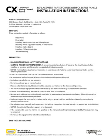
panel microphone connector headset connector 30 talk/listen buttons (ICS-1016E) 14 talk/listen buttons (ICS-1008E) answer-back button clear button six function buttons intercom volume control.Figure 1-1: ICS-1016E Front PanelFigure 1-2: ICS-1008E Front PanelNote: For convenience and ease of use, you can print out labels for panel keys from theEHX configuration software. Open EHX and navigate toMatrix Configuration Panels Panel XX (where Panel XX is the required ICSpanel). Find Print Keys at the top of the configuration screen towards the rightside.Page 7
Panel Microphone ConnectorThis connector allows panel operators to use a panel microphone (see “Panel Mic”on page 1-5). Plugging in a panel microphone will initially cause the panel toswitch to panel-microphone operation and will turn the headset microphone off.Headset ConnectorThe headset connector provides a front-panel connection for a headset. Pluggingin a headset will initially cause the panel to switch toheadset-microphone operation and will turn the speaker off. Unplugging theheadset will cause the panel to switch to panel-microphone operation and will turnthe speaker on.Talk/Listen ButtonsEach talk/listen button can be programmed through the configuration program oran appropriately configured ICS-2008E Master Intercom Panel as a talk (red),listen (yellow), or talk with listen (red). The button color will be dim to indicate ithas a programmed label and is available for selection. When selected it willbecome bright to indicate it is active.Following are descriptions of what the panel’s other indicators mean.Communication-Error IndicatorIf the ICS-1016E/ICS-1008E should lose data communication with the matrixframe, the talk/listen buttons will flash bright red at a slow rate. When datacommunication is restored, the panel will automatically return to normaloperation.Monitoring/Eavesdropping IndicatorsIf any other panel begins monitoring a panel, a beep (the monitoring-alert tone)will sound at the panel.To inhibit the monitoring-alert tone, use the “Configure-Local Preferences” menuin the configuration program.Call-Waiting IndicatorIf a panel calls another panel with a button programmed for that label, the buttonwill rapidly flash bright red. This flashing is a call-waiting tally. To answer theincoming call, push the indicated talk/listen or the “Ans Back” button. The callPage 8
waiting tally can be cleared either by answering the call or by letting the answerback, auto-clear time, which is set in the configuration program, lapse.If another panel calls a panel without a button programmed for that label, it willbe placed in the answer-back stack (see “Removing Labels From the Answer-BackStack” on page 1-5).In-Use Tally IndicatorIf a talk/listen button is assigned to a label and another panel is currently usingthat label, the button will double-flash once per second to indicate the label is inuse. This tally must be specifically enabled from the configuration software.Telephone Off-Hook Tally IndicatorWhen a telephone interface is assigned to a talk/listen button, the button willflash once per second if that telephone is off the hook. This tally must be enabledfrom the configuration program.Radio Receiver Active Tally IndicatorWhen a two-way radio interface port is assigned to a talk/listen button, the buttonwill flash once per second when that radio’s receiver is active. This tally must beenabled from the configuration program.Panel Connected Tally IndicatorThis tally is used when a panel is connected to the frame by a high-speed dataline (such as an ISDN or T1 line) that might beinactive periodically. The talk/listen button for any such panel will flash once persecond when any such panel is on-line. This tally must be enabled from theconfiguration program.Answer-Back FacilityThe “Ans Back” button is used to answer calls to a panel from other panels orinterfaces not assigned to a that panel’s talk/listen buttons. When these callsarrive: The “Ans Back” button will flash bright red. The calling panel’s label will be temporarily assigned to the panel’s “AnsBack” button.Page 9
These two conditions will continue until the call is answered, or until the answerback, time-out period lapses and the caller’s label is automatically removed. Toanswer the call, push the “Ans Back” button. The button will turn bright red,indicating an active talk path to the caller. The talk path is active for as long asthe button is held down.Note: The “Ans Back” button cannot be latched; it is a momentary-only function.To manually remove the caller’s label from the “Ans Back” button, push the“Clear” button. The label assignment will be removed automatically after theanswer-back, time-out period lapses. If another call (or calls) comes in whileanswering a call using the “Ans Back” button: The user will hear the caller’s voice. The calling panel’s label will be placed in the panel’s answer-back stack.To answer the next caller:1)Release the “Ans Back” button.2)Push the “Clear” button to remove the current caller’s label.3)Push the “Ans Back” button to talk to the next caller.Removing Labels From the Answer-Back StackAny label will be automatically removed from the stack if it is not answered withina certain time interval, which is set by the answer-back, auto-clear time in theconfiguration program.To manually remove a label from the answer-back stack press the “Clear” button.Clear ButtonThe “Clear” button, located on the far left in the first row, removes the currentcaller’s label from the “Ans Back” button.Function ButtonsThe function buttons are located on the right-hand side of the front panel.MicThis button activates the panel or headset microphone, whichever has beenselected with the “Panel Mic” button. The button will be bright yellow when thePage 10
selected microphone is active, dim yellow when not active, and off when amicrophone is not present. The “Mic” button also is activated when the useractivates a talk button. If the talk is latched, the microphone will remain on afterthe call.SpeakerThis button toggles the front-panel speaker between active (bright yellow) andinactive (dim yellow). If a headset is not attached the “Speaker” button willdefault to bright yellow and the panel speaker can not be turned off.Panel MicThis button toggles between the panel (bright yellow) and headset (dim yellow)microphones. If only a panel microphone is attached, the button will default tobright yellow and cannot be turned off. If a panel microphone is not attached, thisbutton is off and not functional.Listen/CallThe “Listen/Call” button has four functions: activating the listen-level mode resetting the listen-level settings sending call signals releasing auto-answered telephone lines.Listen-Level ModeSteps to adjust listen volume:1)Latch a listen to an audio source.2)Push (for less than 1 sec.) and quickly release the “Listen/Call” button.3)The button will turn bright yellow to indicate the function is on and all theactive buttons programmed with listen and/or talk with listen will begin toflash. In addition, if the two programmable buttons (located under the“Panel Mic” and “Listen/Call” buttons) are programmed, they will turn fromdim yellow to off.Note: Only active talk/listen buttons programmed with listen or talk with listen can beadjusted in listen-level mode.Page 11
4)Push the appropriate talk/listen button programmed as a listen or talkwith listen. The selected button will turn bright yellow and theprogrammable buttons with the up and down arrows will turn dim yellow.5)Use the up and down arrows on the programmable buttons to increase (uparrows) or decrease (down arrows) the crosspoint volume of the selectedlisten or talk with listen button.6)To exit, push the “Listen/Call” button or wait for the 3 sec. time-out.Listen Level ResetTo reset the listen level:1)Push (for less than 1 sec.) and quickly release the “Listen/Call” button toactivate the listen-level mode. The “Listen/Call” button will turn brightyellow and the active talk/listen buttons programmed with listen and/ortalk with listen will flash.2)Push and hold the “Listen/Call” button for 3 sec. to reset the listen levelsettings to the default. The active talk/listen buttons programmed withlisten and/or listen with talk will stop flashing and all the programmedtalk/listen buttons will return to their previous states.3)Release the “Listen/Call” button.Call SignalsTo activate call signals:1)Push and hold the “Listen/Call” button until it is dim yellow (at least 1sec).2)Push the talk/listen button programmed with a talk or talk with listen ofthe desired destination’s label. The call signal will be sent each time thedestination’s talk/listen button is pressed.3)The call-signal mode will time-out after 5 sec. of button inactivity or canbe deactivated by pressing the “Listen/Call” button.Call signals can be issued to any talk or talk with listen destination assigned to apanel’s talk/listen buttons. If more than one label is assigned to a button, allPage 12
labels will receive the signal. If a label is a fixed group, the entire group willreceive the call signal. If the label is a party line, then every panel listening on theparty line will receive the call signal.Remote Telephone Line ReleaseThis function is available only if specifically enabled in the configuration program.To hang up a telephone interface left off the hook:1)Push and hold the “Listen/Call” button for at least 2 seconds until it isbright yellow to activate the call-signal mode.2)While holding the “Listen/Call” button, press the talk/listen buttonprogrammed with talk or talk with listen of the desired telephone’s label.3)Release the “Listen/Call” button.Note: In addition to hanging up the telephone interface, this will deactivate any audiopath set to the interface from anywhere in the system.Programmable ButtonsThe two programmable buttons, located in the last row on the right-hand side ofthe front panel, can be programmed through theconfiguration program. In default mode, these programmable buttons increase(left button) or decrease (right button) the crosspoint volume (see “Listen/Call”on page 1-5).The two programming modes are:Local ExclusiveAllows the user to isolate an assigned talk/listen button by turning off the audiopaths from all other active (brightly lit) talk/listen buttons.If a talk/listen button programmed as a talk is selected for local exclusive, onlyother active talks will be turned off. If a talk/listen button programmed as a listenis selected for local exclusive, only other active listens will be turned off. If atalk/listen button programmed as a talk with listen is selected for local exclusive,all other active talk/listen buttons will be turned off.To activate this function:Page 13
1)Push the programmable button programmed with the local exclusiveoption. This will turn the button bright yellow and turn off the otherprogrammable button and the “Listen/Call” button.2)Push the appropriate programmed talk/listen button. This will turn thatbutton on brightly and turn off all other active and/or programmedbuttons.3)To exit this momentary-only function, release the selected talk/listenbutton. All buttons will return to their previous state(s).Note: This function does not work with the “Ans Back” button.Local Page OverrideAllows other panels to hear the user/pager through the individual panels’ speakersregardless of their speaker on/off status or volume level (see “Page OverrideLevel Control” on page 1-9).To activate this function:1)Push the programmable button programmed for local page override. Thiswill turn off the other programmable button, the “Listen/Call” button, andall inactive talk/listen buttons only programmed with listens.2)Push the appropriate talk/listen button programmed for talk or talk withlisten. This will turn that button bright red and momentarily makeunavailable all the other programmed talk/listen buttons programmed withtalk or talk with listen.3)To exit this momentary-only function, release the talk/listen button. Allbuttons will return to their previous state(s).Note: This function does not work with the “Ans Back” button.Intercom Volume ControlThis knob sets the volume level for all incoming Matrix frame audio, except forpaging communication (see page 9).1.2.2ICS-1016E/ICS-1008E rear-panel connectors and controlsThe panels have identical rear-panel connectors and controls. They are:Page 14
power supply connector DB-9 female connector RJ-45 connector speaker mute level control page override level control headset microphone sidetone control headset microphone gain control panel microphone gain.Figure 1-3: ICS-1016E/ICS-1008E Rear PanelPower Supply ConnectorThe panels operate with DC power.DB-9 Female ConnectorThe female DB-9 connector, labeled Expansion, is used to connect either panel toan EXP-1016E.RJ-45 Connector to MatrixThe RJ-45 connector connects the panel to the Matrix frame.Page 15
Speaker Mute Level ControlThis knob adjusts the speaker level when any talk is active at the panel. Thisfunction helps prevent possible feedback. The maximum amount of muting is 15dB below full volume. If the rear-panel control is set below that level, then mutingwill have no effect. When shipped from the factory, the mute level is adjusted toprovide a -6dB attenuation.Page Override Level ControlThis knob adjusts the page override level. Page Override is a special function inthe panel in which the intercom volume defaults to a preset a value or the currentfront-panel volume control setting (whichever is higher) when commanded to bythe central matrix. Any fixed group can be assigned the page-override functionthrough the configuration program. When shipped from the factory, the pageoverride level is adjusted to the equivalent of half volume.Headset Microphone Sidetone ControlThis knob adjusts the headset sidetone level. Sidetone is the sound of the user’svoice in his headset. When shipped from the factory, the sidetone is adjusted formaximum sidetone.Headset and Panel Microphone Gain ControlsThese knobs adjust the gain of the headset and panel microphones. Thepreamplifier gain of the panel and headset microphone can be adjusted over arange of 0 to 20 dB. When shipped from the factory, the headset microphone gainis set to 10 dB and the panel microphone gain is set to 0 dB.If two panels are talking to each other at the same time with the panelmicrophone gain set to maximum, feedback may occur even if the Speaker Mute(see “Speaker Mute Level Control” on page 1-9) is set to maximum. In this case,it will be necessary to turn the panel microphone gain down. Similarly, in somenoisy environments it may be necessary to turn the panel microphone gain downand have the operator talk more closely into the microphone.Page 16
2InstallationThis chapter describes the installation procedure of the ICS-1016E and ICS-1008EPanels and their associated EXP-1016E expansion panel. For operationinformation, see chapter 1 of this manual; for troubleshooting and maintenanceinformation, see chapter 3 of this manual and for programming information, seethe Eclipse Configuration System manual.2.1Equipment mounting2.1.1ICS-1016E/ICS-1008EPut all intercom panels at a comfortable operational height. Leave at least 2 in. ofclearance at the rear of the panel’s chassis to allow for cable connectors andaccess to the rear-panel controls.2.2Wiring2.2.1ICS-1016E/ICS-1008EThe ICS-1016E/ICS-1008E uses a twisted, 4-pair transmission scheme to connectit to the frame using the industry standard RJ-45 connector. Refer to the EclipseInstallation Manual for RJ-45 connector installation and use, and the type of cableneeded for connection between panels and frames.Each pair of the twisted, 4-pair wire has the following function: pair 1 transmits analog audio from the matrix port to the panel pair 2 transmits digital data from the panel back to the matrix card port pair 3 transmits audio from the panel to the matrix card port pair 4 transmits digital data from the matrix port back to the panel.Page 17
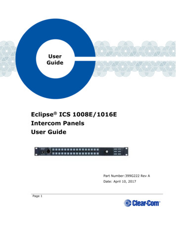
ATT-T568B (Modular Jumpers Wired One to One)Matrix Frame EndPanel EndPair2RS-422 Receive 11RS-422 Receive -22Audio Receive 3Audio Send 4Audio Send -5Audio Receive -6RS-422 Send 7RS-422 Send -8Pair134Pair356Pair47812345678Rear view of connectorFigure 2-1: Matrix Frame to Panel Wiring2.3Mains ac power2.3.1ICS-1016E/ICS-1008EThe panels have an external DC power supply with a removable AC power cord.The power supply is “universal,” operating over a voltage range of 90 to 260 VACand 45 to 65 Hz. The maximum dissipation is 30 W. A bracket has been providedto mount this external supply, if necessary.Page 18
2.4Adjustments2.4.1ICS-1016E/ICS-1008EThe panels have identical rear-panel controls. They are: speaker mute level control page override level control headset microphone sidetone adjustment headset microphone gain adjustment panel microphone gain.Figure 2-2: ICS-1016E/ICS-1008E Rear PanelSpeaker Mute Level ControlThis knob adjusts the speaker level when any talk is active at the panel. Thisfunction helps prevent possible feedback. The maximum amount of muting is 15dB below full volume. If the rear-panel control is set below that level, then mutingwill have no effect. When shipped from the factory, the mute level is adjusted toprovide a -6dB attenuation.Page 19
Page Override Level ControlThis knob adjusts the page override level. Page Override is a special function inthe panel in which the intercom volume defaults to a preset a value or the currentfront-panel volume control setting (whichever is higher) when commanded to bythe central matrix. Any fixed group can be assigned the page-override functionthrough the configuration program. When shipped from the factory, the pageoverride level is adjusted to the equivalent of half volume.Headset Microphone Sidetone ControlThis knob adjusts the headset sidetone level. Sidetone is the sound of the user’svoice in his headset. When shipped from the factory, the sidetone is adjusted formaximum sidetone.Headset and Panel Microphone Gain ControlsThese knobs adjust the gain of the headset and panel microphones. Thepreamplifier gain of the panel and headset microphone can be adjusted over arange of 0 to 20 dB. When shipped from the factory, the headset microphone gainis set to 10 dB and the panel microphone gain is set to 0 dB.If two panels are talking to each other at the same time with the panelmicrophone gain set to maximum, feedback may occur even if theSpeaker Mute (see “Speaker Mute Level Control” on page 2-4) is set to maximum.In this case, it will be necessary to turn the panel microphone gain down.Similarly, in some noisy environments it may be necessary to turn the panelmicrophone gain down and have the operator talk more closely into 008EAssign each panel’s name and other parameters by using the EclipseConfiguration System (ECS) program (see the ECS manual for more information).Page 20
3MaintenanceThis section provides panel microprocessor resetting instructions, troubleshootingguidelines, assembly drawings, schematics, and component lists.3.1Panel resetIf the panel is acting erratically, try resetting it by unplugging the panel from ACpower and reconnecting or by simultaneously pressing the “Mic,” “Speaker,” andup and down arrow buttons.3.2TroubleshootingWhen experiencing the symptoms listed below, attempt the following solutions inthe order outlined. The solutions are listed in order of difficulty with the first beingthe most simple and easy. For troubleshooting guidelines for the entire system,see the “Overview” chapter of this manual.3.2.13.2.2The panel’s front-panel indicators fail to light1)Check mains AC power into the panel.2)Ensure the external power supply is properly connected to the panel.3)Replace the panel.The LED behind the talk/listen button does not light whenthe key is pressed1)Ensure the button has a label assigned to it (the LED indicator will notlight without an assigned label).2)Reset the panel.3)Replace the panel.Page 21
3.2.33.2.4The panel appears to activate talk paths, but other panelscan’t hear the panel operator1)Check “Mic On/Off” and “Panel Mic” buttons to ensure the intendedmicrophone is selected and on.2)If the correct microphone is turned on, ensure the panel audio has notbeen muted externally through the logic inputs.3)Make sure the panel has not been defined as a nearby panel.4)Enable eavesdropping on the panel.5)Test the integrity of the panel’s audio path by temporarily setting a forcedlisten to it.6)Reset the panel.7)Replace the panel.No audio from the panel’s speaker1)Ensure the “Intercom” knob on the panel’s front panel is turned up.2)Ensure the “Speaker” button is on.3)Check whether audio can be heard in a headphone.4)Test the integrity of the panel’s audio path by temporarily setting a forcedlisten to it.5)Reset the panel’s matrix card in the Matrix frame.6)Replace the panel’s matrix card in the Matrix frame.7)Reset the panel.8)Replace the panel.Page 22
3.2.53.2.63.2.73.3The operator cannot hear another panel’s page1)Adjust the panel’s rear-panel “Page” control.2)Check the panel’s configuration to see if the page override inhibit is set.Announce tones (call signal tones, eavesdroppingindication, etc.) aren’t heard at the panel1)Adjust the panel’s rear-panel “Page” control.2)Check the panel’s configuration to see if page override is set.Accessory panel keys do not function1)Check the accessory panel’s connection on the panel’s rear panel.2)Check the configuration program to ensure the correct number ofaccessory keys has been configured.ServicingFigure 3-1 illustrates the steps required to disassemble an ICS-1016E/ICS-1008Efor servicing. The disassembly steps are:1)Remove the unit from the rack.2)Remove both screws from each side that are holding the rack ears inplace.3)Remove the rack ears.4)Remove the four screws holding the PCB in place.5)Remove the three screws holding the front panel in place.Note: Do not disc
flash once per second if that telephone is off the hook. This tally must be enabled from the configuration program. Radio Receiver Active Tally Indicator When a two-way radio interface port is assigned to a talk/listen button, the button will flash once per second