Transcription
Participant's ManualDisplays, Indicators andControls E90BMW ServiceAftersales Training
The information contained in this Participant's Manual is intended solely for the participants ofthis seminar run by BMW Aftersales Training.Refer to the latest relevant "BMW Service" information for any changes/supplements to theTechnical Data.Information status: October 2004conceptinfo@bmw.de 2004 BMW GroupAftersales Training, München, Germany.Reprints of this manual or its parts require the written approval of BMW Group,München.
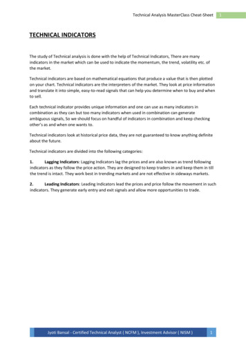
Participant's ManualDisplays, Indicators and ControlsE90Concise information at a glanceController also in the BMW 3 SeriesMore discrete appearance of the interiorthrough less switches
Information on this Participant's ManualSymbols usedThe following symbols are used in this Participant's Manual to facilitatebetter comprehension and to draw attention to important information.3 contains information for better understanding of the describedsystems and their functions.1 identifies the end of an item of information.Current content of Participant's ManualIn view of the constant further developments in the design and equipmentof BMW vehicles deviations may arise between this Participant's Manualand the vehicles made available as part of the training course.The background material refers exclusively to left-hand drive vehicles.The controls are in part arranged differently in right-hand drive vehiclesthan shown on the graphics in the Participant's Manual.Additional information sourcesYou will find further information on the individual vehicle topic in the BMWdiagnosis and repair systems as well as on the Internet underwww.bmw.com.
ContentsDisplays, Indicators andControlsObjectives1Introduction3An inspired conceptInstrument ClusterCentral Information Display (CID)ConnectedServicePersonal profile34567System overview9Instrument clusterCentral Information Display (CID)912Functions15Instrument clusterCentral Information Display (CID)Personal Profile152021System components23Instrument ClusterCentral Information Display (CID)ConnectedService253234Service information39Instrument ClusterCentral Information Display (CID)ConnectedService394243Summary45Points to remember45Test questions49
2ObjectivesDisplays, Indicators and ControlsReference material for practical applicationsto accompany you throughout the training courseThis Participant's Manual provides informationon the compact operational control concept aswell as the ergonomically designed and wellpositioned display, indicator and controlelements in the new BMW 3 Series.This manual is designed to provide essentialinformation throughout the training courseand complements the seminar material usedin the BMW Aftersales Training course. It canbe used both as a basis for self-study as wellas a reference document.While preparing for the technical trainingcourse and in connection with the practicalexercises, this information is designed toenable the participant to perform service workin the area of the display, indicator and controlelements on the new BMW 3 Series.Previous technical and practical knowledge ofthe BMW 1 Series, 5 Series and 7 Series willfacilitate better understanding of thecorresponding systems and their functions.It is important that you work throughthe training and information program(SIP) on this subject.Basic knowledge ensurescompetence in theory and practicalapplications.1
22
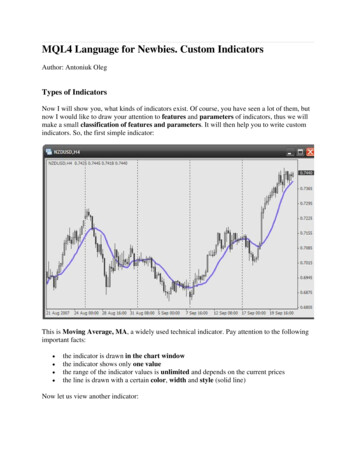
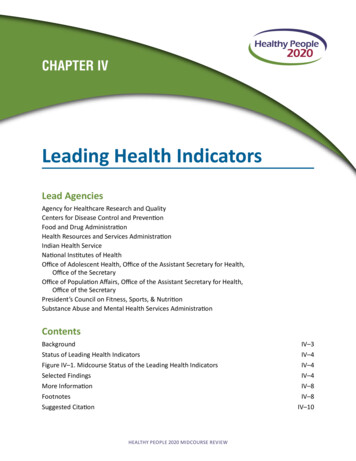
3IntroductionDisplays, Indicators and ControlsAn inspired conceptClear differentiation and optimum structuringof the cockpit are the prerequisite for the morediscrete and subtle appearance of the interior.Fewer switches simplify logical operation inthe new BMW 3 Series.The display, indicator and control elementsare organized in a hierarchical arrangementcorresponding to their function - "Mostimportant at the top - less important at thebottom"The Participant's Manual is subdivided intothe following sections: Instrument cluster Central Information Display (CID) ConnectedService Personal profile.Depending on the equipmentconfiguration, it is possible tooperate all comfort functions andseveral vehicle functions via thecontroller in the BMW 3 Series.Display, indicator and control concept1 - BMW 3 Series display, indicator and control conceptIndex12DescriptionSteering column stalk/steeringwheelInstrument clusterIndex3DescriptionCentral Information Display (CID)4Controller3
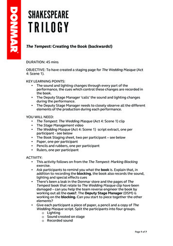
3Instrument ClusterThe new BMW 3 Series is equipped with aninstrument cluster featuring analogueinstruments for: Speed Engine speedA classic two-dial design drawsattention to both instruments. Eachfinished unobtrusively with two trimrings in pearl-finish chrome. Economy control and Fuel level.Two large pointer instruments show the roadspeed and engine speed.2 - Basic instrument cluster, diesel4Two smaller pointer instruments display fuellevel and current fuel consumption.The scales in the instrument cluster arespecific to the country, vehicle and engine.All of the indicator lamps are located in thecentre at the top between the two largeinstrument dials.The LC display is located in the centrebetween the two large pointer instruments.
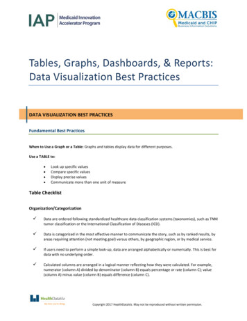
3Central Information Display (CID)The central information display (CID) is thegraphic display unit for the user interface of allconvenience functions and several vehiclefunctions.The main menu consists of four menu items: Communication NavigationAll individual user settings are combined underthe additional "Settings" menu.The button for selecting the main menu islocated behind the controller in the centreconsole.The new BMW 3 Series offers thesame convenient operating andcontrol functions as the mid-rangeand luxury BMW models.As on the mid-range and luxury BMW models,the system is operated by means of thecentral control element, the controller. Entertainment Climate control.3 - Central InformationDisplay (CID)The design of the central information display isidentical to that of the CID installed in theBMW 5 Series.In the BMW 3 Series, the same software isused in the central information display as in theBMW 5 Series and in the BMW 1 Series.All functions are identical and are described inthe BMW 3 Series Owner's Handbook.5
3ConnectedServiceThe KeyReader is an importantConnectedService module. Servicereception is able to read the datastored in the vehicle key with theKeyReader.ConnectedService has been part of theservice concept of the BMW Group since theintroduction of the BMW 7 Series.ConnectedService is an indication of howcommunications and networking between thecar and Service are increasing.ConnectedService is made up of severalmodules; some of these are already inoperation while others have been furtherdeveloped or introduced for the first time withthe launch of the BMW 3 Series.TeleService1 can even make an automaticServiceCall which informs the customer'shome dealer that a service is due.4 - ConnectedService modules6
3Personal profileThe "Personal profile" systems allows thedriver to set several functions of the BMW 3Series to suit his/her personal requirements.Personal profile stores the data entered by thedriver such as automatic setting of the outsidemirrors or speed-dependent volume in thecorresponding control units.As soon as the vehicle is unlocked using theremote control, the system recognizes thecorresponding settings belonging to theremote control.Up to three different basic settings can beadapted for three different persons. Theprecondition is that each of the three personshas his/her own remote control.The BMW 3 Series caters for thedriver's personal requirements.5 - Personal profile7
38
4System overviewDisplays, Indicators and ControlsInstrument clusterInput/outputUnlike the previous model variants,the instrument cluster in the BMW 3Series has no gateway function.1 - Input/outputThe input/output key is identical to that of thesystem circuit diagram and is provided afterthe system circuit diagram.9
4System circuit diagramAs can be clearly seen in the system circuitdiagram, the instrument cluster on the BMW 3Series has no gateway function.2 - System circuit diagram10Only the outside temperature, the informationfrom the steering column switch cluster andfootwell module are shown directly in thedisplay.
4Index12345678910DescriptionOutside temperature sensorIndex11DescriptionBrake pad wear sensor,rear rightCoolant level switch12Washer fluid level sensorBrake pad wear sensor, front left 13Fuel level sensor, rightDynamic Stability Control (DSC) 14Fuel level sensor, leftDigital motor electronics DME PT-CAN Powertrain Controller Area Networkor DDEFootwell module FRMD-BusDiagnostics busSteering column switch cluster K-CAN Body Controller Area NetworkInstrument clusterKl. 30Terminal 30 (power supply)Junction box JBKl. 31Terminal 31 (ground)Contact switch, handbrakeConnector assignments of the instrument clusterThe 18-pin plug connection (1) is located atthe rear of the instrument cluster.3 - 18-pin plug connection11
4Central Information Display (CID)Input/outputThe following illustration shows all controlunits and control elements that are connecteddirectly to the central information display CID.4 - Input/output central information display CIDThe input/output key is identical to that of thesystem circuit diagram and is provided afterthe system circuit diagram.12
4System circuit diagram5 - System circuit diagram central information display CIDIndex1234DescriptionJunction box control unitDSC control unitMultifunction steering wheelCentral information displayIndex567DescriptionMulti-audio system controllerControllerInstrument cluster13
414
5FunctionsDisplays, Indicators and ControlsInstrument clusterThe instrument cluster receives informationon the wiring harness in the form of analogueand digital electrical signals. These signals areprocessed and displayed in the instrumentcluster or passed on as information to othercontrol units.The instrument cluster on the BMW 3 Seriesfeatures several functions that have beenchanged compared to previous models.Moving dial indicatorMovement ring gear (3) connected to the dial,Fig. 1 shows the movement sequence of themoving dial indicator based on the rev counter. pinion (6) andThe moving dial indicator (2) is driven by stepper motor (7) secured to the rear of pcboard (5).1 - Moving dial indicator in the BMW 3 Series High instrument clusterIndex1234DescriptionFront frameMoving dial indicatorRing gearLight guideIndex5678DescriptionPC-boardPinionStepper motorBase plate15
5Fuel gaugeFuel reservereserve level is reached.The fuel reserve levelis not indicated by anindicator lamp as in theprevious models. Afuel pump symbollights up for 23seconds in the LCdisplay as soon as theThis display is permanently activated at arange below approx. 50 km.On-board computerMain menuA graphic symbol in the upper display windowis assigned to each main menu item.Menu items that are deactivated duringvehicle operation are not shown.Each menu can be interrupted at a certainposition by briefly pressing the BC button.16In addition to this active termination, there isan automatic termination that takes place 15seconds after the last entry.The display for the M-ASK and CCC areshown on the central information display CID.
5BC main menu2 - BC main menuThe following table lists all BC functions thatcan be selected in the instrument clusterdepending on the options.17
5BC function in the instrument clusterFunctionActiveas 8 gSettings are stored immediatelyCheck ControlmessagesKL. R EIN Error message system with max.72 symbolsError prioritizationAudible warningText message as from radiostage 3/4Engine oil levelmeasurementDisplayTerminal15Measurement with vehiclestationary and in operationClock symbol in servicing modeNo electrical measurement fordiesel engines"Service2" displayed in case offaultMultiple initialization possibleTyre failureindicator RPATerminal15TimeKL. R EIN Menu selection via cursorDateXXXXXXXXXXKL. R EIN Menu selection via cursorCBS4workshopmodeTerminal15Activation via reset buttonON time 10 secCBS4Terminal15Setting of main inspection/exhaust emission inspectionsame as data entryPersonalprofile settingsTerminal15Changing/resetting unitsX Can be selected via instrument cluster18RAD1/2 MASK/CCCXXX
5Operating example:Tyre failure indicator RPA3. Confirm the display by briefly pressing theBC button on the steering column stalk.Initialization must be performed immediatelyafter correcting the tyre pressure, a tyrechange or a wheel change.4. Press and hold the BC button on thesteering column stalk for approx. 5seconds until the RPA display lights up inthe instrument cluster.The tyre failure indicator is now ready forinitialization.If no tick is shown in the display, thisindicates that the tyre failure indicatorcannot be initialized due to a fault.The following procedure must be performedto initialize the system:1. Start the engine but do not drive off.2. Press the rocker switch on the steeringcolumn stalk until the "initialising tyrefailure indicator" function is shown in theinstrument cluster.5. Release the BC button to concludeinitialization.3 - Initialization of the tyrefailure indicator RPAOperating example:Instrument lightingThe side lights or low beam headlights mustbe switched on in order to control the lightingintensity (dimming).The following procedure must be performedto set the system:1. Press the rocker switch in the steeringcolumn stalk up or down until the"instrument lighting" function appears inthe instrument cluster.4 - Setting instrument lightingThe procedure for selecting and correctingthe functions2. Confirm the display by briefly pressing theBC button on the steering column stalk. Check Control messages3. Press the rocker switch up or down toselect the lighting intensity. Each settingis saved immediately. Time4. Press the BC button on the steeringcolumn stalk to exit the menu. CBS4 and Oil level measurement Date Personal profile PP settings.is identical and is described in the BMW 3Series Owner's Handbook.19
5Central Information Display (CID)The central information display CID isdesigned the same as the CID installed in theBMW 5 Series and BMW 7 Series.User interfaceThe user interface in the CID is identical to thatof the CID installed in the BMW 5 Series andBMW 1 Series.5 - User interface in the central information display (CID)20A detailed description of the main menu and ofthe procedure for selecting the individualfunctions is provided in the BMW 3 SeriesOwner's Handbook.
5Personal ProfileDisplay in the instrument clusterDisplay formats and units of measureChanging unit of measureThe following display formats and units ofmeasure can be changed in the instrumentcluster:The following procedure must be carried outin order to change the unit of measure: Fuel consumption (l/100 km, mpg, km/l) Distance (km, mls) Time format (12h/24h) Date format (dd/mm, mm/dd) Temperature ( C, F) Reset of display formats and units ofmeasure, the factory setting is adopted.The procedure for selecting and changing alldisplay formats and units of measure isidentical. By way of example, the procedure forchanging the unit of measure is described indetail.1. Press the rocker switch in the steeringcolumn stalk up or down until the"Personal Profile" function appears in theinstrument cluster.2. Press the BC button on the steeringcolumn stalk.3. Press the rocker switch up or down untilthe required unit of measures is shown.4. Press the BC button on the steeringcolumn stalk.5. Use the rocker switch to make thenecessary change.6. Press the BC button to adopt the change.6 - Changing unit of measure21
522
6System componentsDisplays, Indicators and ControlsGreat variety of different versions20 variants of the instrument cluster areavailable for the E90.The following table lists the 10 variants thatcan be installed in the Basic and High versions.Country-specific variantE9x ECE LLE9x ECE RRE9x USE9x JPNEngine variant4-cylinder petrol engine4-cylinder petrol engine4-cylinder petrol engine4-cylinder petrol engineE9x ECE LLE9x ECE RRE9x USE9x JPN6-cylinder petrol engine (NG6)6-cylinder petrol engine (NG6)6-cylinder petrol engine (NG6)6-cylinder petrol engine (NG6)E9x ECE LLE9x ECE RR4/6-cylinder diesel engine4/6-cylinder diesel engineThe following table provides an exactcomparison, illustrating the functions andsymbols that have changed compared to theBMW 3 Series (E46).FunctionE90 BasicE90 HighE46Analogueinstrument Speed Speed- moving dialindicator - Speed Engine speed Fuel gauge Economy control Engine speed Fuel gauge Economy controlIndicator lampsService indicatorCheck controlmessagesPictographsDoor open LightfailureFuel reserveUnit masterESS/SSGindicatorMaximum 15CBS4CC system, multicoloured (yellow/red)Included in CC systemContained in CC system(incl. range indication)ImplementedIntegrated in main display (codeable) Engine speed Fuel gauge Economy control Coolanttemperature gaugeMaximum 24SIA4---5 door/lid symbols4 lamp failure symbolsFixed indicator lampNot usedAdditionalLC display(specific variant)23
6FunctionMain displayBC functionsE90 BasicE90 HighVariable indicator lamps (multicoloured) fixeddisplay (2-line)- Basic (0.5 pitch, single colour)- High (0.32 pitch, single colour)Standard features- Range- Average speed- Average fuel consumptionPermanent in variable indicator fieldClock/outsidetemperatureindicatorDimmer (terminal BC function58g)Display/indicators in instrument clusterPhotosensorCentral photosensor in instrument clusterGateway functionOil levelmeasurementTyre failureindicator RPAClockNo (junction box function)BC function (petrol engine)Indication in instrument clusterBC functionDisplay/indicators in instrument clusterBD functionIndication in instrument clusterDateBD functionIndication in instrument clusterCondition-based BD functionservice CBS4Indication in instrument clusterPersonal Profile BD functionPPIndication in instrument cluster24E46Display with 7 fixedsegment LCD (singlecolour)Special features(model-specific)Integrated in BCThumb wheel in lightswitch cluster LSZCentral photosensorin light switch clusterLSZYes--Button Centre columnswitch cluster SZMButton in instrumentclusterButton in instrumentcluster--Encoding bydealership network(minimum features)
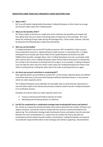
6Instrument ClusterLocation/componentsLocationThe instrument cluster is secured by means oftwo pan-head tapping screws to theinstrument panel.ComponentsThe instrument cluster comprises thefollowing components: Instrument dials Indicator and warning lamps Program and gear display for automatictransmission and sequential manualgearbox Acoustic generator for audible directionindicator signal and CC gong for radio 1 andradio 2.The audible signals are output via the radiospeaker in connection with radio 3 and radio4.Driver control request of ACC with radio 1. Button for resetting trip distance recorderand selecting condition-based service inCBS menu.Press button for 4 seconds to select theworkshop menu. The settings are selectedvia the rocker switch in the steering columnstalk.cluster (see system overview/system circuitdiagram).The following components are described indetail: Display areas Indicator and warning lamps LC display.The set speed for the cruise controland the warning zone of the revcounter are realized by a moving dialindicator in the High variant. Themoving dial indicators are locateddirectly behind the speedometerand rev counter scales.Display areasThe instrument cluster features display areasfor: Speedometer Rev counter Economy control (fuel consumptionindicator) Fuel gauge Outside temperature display Indicator and warning lamps LC display Program and gear displays for automatictransmission and sequential manualgearbox SMG.A shroud prevents reflections in the acutelyangled windscreen. Connected components which serve toactivate the displays in the instrument1 - Pointer instruments, example - High, petrol engine25
6SpeedometerOutside temperature displayTwo variants of the speedometer are availablefor the BMW 3 Series. The signal chain isidentical to the signal chain of the rev counter.A temperature sensor measures the outsidetemperature and displays it in the instrumentcluster.In ignition key position 0, the instrumentcluster applies terminal 30g current to thetemperature sensor every 10 minutes.VariantUnitECE, JPN km/hUK, USmphkm/hReading0 20 40 60 80 2600 20 40 60 1600 20 40 60 80 . 260The instrument cluster makes available thecurrent outside temperature in the form of adata telegram via the K-CAN.Rev counterIndicator and warning lampsOn the BMW 3 Series, engine speed isdisplayed using the following signal chain:The indicator and warning lamps are activatedby the processor in the instrument cluster. The DME control unit sends the enginespeed on the PT-CAN and K-CAN.All important and legally stipulated indicatorand warning lamps are activated at terminal 15ON during the pre-drive check. Using a characteristic curve, step pulses foractuating the stepper motor are assigned tothe effective engine speed.There are two variants of the rev counter forvehicles with 4-cylinder engines: On petrol engines, up to 7000 rpm On diesel engines, up to 5500 rpm.3The engine speed range is increased to7500 rpm on vehicles equipped with 6cylinder petrol engines. 1Economy control (fuel consumptionindicator)The economy control is an analogue indicatorin the instrument cluster.2 - Indicator and warning lamps - Basic variantFuel gaugeThe fuel level is indicated by a pointerinstrument integrated in the speedometer onthe left.A pictogram of a fuel gauge lights up in theinstrument cluster when the level drops belowa factory-coded threshold (standard 8 lpetrol, 6.5 l diesel).A warning tone additionally sounds onreaching the reserve threshold.3 - Indicator and warning lamps - High variantThe indicator and warning lamps can beilluminated in different colours orcombinations.The significance of the indicator and warninglamps as well as the colour assignments aredescribed in detail in the BMW 3 SeriesOwner's Handbook.26
6LC displayProgram and gear displayThe LC display is divided into two areas.The program and gear display is shown in thebottom window in the LC display on vehicleswith automatic or manual transmission.The time and outside temperature are shownin the upper display along with the CCmessages and CBS images.The on-board computer functions, CBSmessages, distance recorder as well as theprogram display for automatic transmissionare shown in the lower display.The program and gear display shows lettersand numbers. The program mode is displayedall the time and is not overwritten by otherinformation.On manual transmission vehicles, the geardisplay is blanked out by means of the codingand an enlarged version of the BC display iscoded instead of it.6 - Program and gear indicator - Basic variant4 - LC display - Basic variant7 - Program and gear indicator - High variantAcoustic generatorsAudible warnings are given in support of checkcontrol messages. The instrument clustercontrols these warnings via the K-CAN. Thewarning signals are output by the MASK/CCCcontrol unit when installed as an option.5 - LC display - High variantManipulation dotDifferent data are stored in the instrumentcluster and in the CAS when a dot appears tothe left of the trip distance recorder.The acoustic generator in the instrumentcluster sounds the warnings if radio 1 or radio2 is installed in the vehicle.The footwell module is responsible for controlof the direction indicator function via the KCAN.The manipulation dot is indicated when, forexample, comparison of the stored vehicleidentification number does not agree.3Different data may be caused, forexample, by replacing on of these two controlunits. 127
6Lighting/dimming of display instrumentsThe instrument cluster is illuminated in thelights ON setting.The instrument cluster calculates thebrightness of the lighting (dimming) of thedisplay, pointer instruments. The brightnesssetting is distributed over the K-CAN to furthercontrol units such as the CID in the vehicle.When the vehicle lighting is switched on, thedimmer control is matched with thephototransistor integrated in the instrumentcluster. The lighting intensity can be setindividually in the BC menu via the rockerswitch on the steering column.288 - Setting lighting/dimmer via the steering column stalkWhen the vehicle lighting is switched off, thesystem is controlled only by thephototransistor so that the display brightnessis determined by the ambient light.
6US variantThe main difference compared to the EU LHDinstrument cluster is in the speed scale whichshows both mph (miles per hour) and km/h(kilometre per hour).In addition, fuel consumption is shown in mpg(miles per gallon).9 - Instrument cluster, US variantThere is a further difference compared to theEU variant in the arrangement andrepresentation of the indicator and warninglamps.The following symbols are replaced by words:SymbolWordsAudible warningsUS vehicles additionally feature an ignition keywarning and a seat belt warning.An uninterrupted warning tone sounds whenthe driver's door is opened with terminal 15OFF and the identification transmitter in place.The audible signal is switched off by removingthe identification transmitter, closing the dooror after 30 minutes.The seat belt warning is activated at terminal15 ON if the seat belt contact is not closed.The audible warning is intermittent and is nolonger than 6 seconds. The indicator andwarning lamp remains on.3The indicator lamp for the rear fog light isnot active in the US variant. 129
6JPN variantThe main difference compared to the EU LHDinstrument cluster is in the economy controlwhich showskm/l instead of l/100 km.10 - Economy control - instrument cluster, JPN variantOn-board computerThere are two versions of the computeravailable for the BMW 3 Series: On-board computer as basic version andon-board computer as journey computer;which can be activated by encoding,depending on the vehicle equipmentspecification.The basic on-board computer contains thefollowing functions: Average fuel consumption 1 Range Current consumption Average speedFor the journey computer, the computer isexpanded to include the following additionalfunctions: Start of journey Duration of journey Distance covered Arrival time Average fuel consumption 2 Average speed 2 Remaining distance.The individual functions of the basic version ofthe computer can be shown in succession inthe LC display of the instrument cluster. Thedata description is the same as that for theother BMW models.3The journey computer is shown only inthe option SA 555 CID. 130
6Display variantsThere are two display variants of the on-boardcomputer functions in the instrument cluster.11 - Display of on-boardcomputer functionsIndex12DescriptionComputer in vehicle with automatic transmissionComputer in vehicle with manual transmissionThe menu rocker switch must be pressed forat least 2 seconds in one direction to enablefast scrolling of all menu items. The menu isthen scrolled through at intervals of 0.5seconds.Show displaysThe BC displays are shown and scrolled in theinstrument cluster via a menu rocker switch onthe steering column stalk for the directionindicator lights.The individual functions are displayed in thelower display window of the instrumentcluster.Once terminal R is switched on, the computerwill display the computer function that wasdisplayed last.All other functions can be selected by meansof the rocker switch on the steering columnstalk.The order in which the BC functions areshown is always the same.The main menu is described in detail in thesection "Functions".12 - Steering column stalk for direction indicator lightsIndex12DescriptionBC buttonMenu rocker switch31
6Central Information Display (CID)Location/componentsLocationThe central information display CID is securedwith two pan-head tapping screws in thecentral area of the instrument panel.13 - Central InformationDisplay (CID)ComponentsLC displayThe CID comprises the following twocomponents:To accommodate the different equipmentvariants, two versions of the LC display areavailable in the new BMW 3 Series: Casing with integral electronic module Casing attachment with glass cover.The controller which is used to control thedisplays and indicators in the CID is also anintegral part of the CID system. LCD 6.5" MID in connection with M-ASKThe display is equipped with a digital 6.5"TFT screen (Thin Film Transistor) with avisible area of 143.4 mm x 79.32 mm. Theresolution of the TFT display is 400 x 3 x240 pixels. LCD 8.8" High in connection with CCCThe display is equipped with a digital 8.8"TFT screen (Thin Film Transistor) with avisible area of 209.28 mm x 78.48 mm. Theresolution of the TFT display is 400 x 3 x240 pixels.32
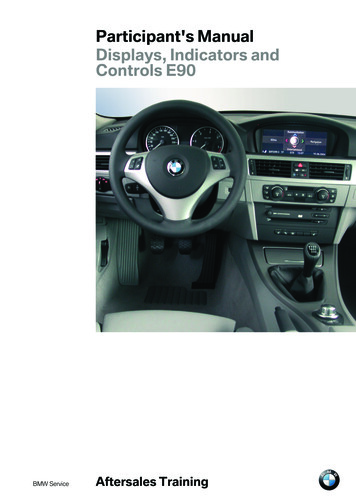
6ControllerThe controller is the central operating controlfor all comfort functions and selected optionsfor some vehicle functions that are displayedon the central information display.The controller is located in the centre consoleimmediately behind the gear selector lever,within reach of the user (driver and frontpassenger).There are two variants, as follows: Basic variant in connection with M-ASKThe basic variant features a notchmechanism with 24 notch settings perrevolution. High variant in connection with CCCThe tactile feedback for the rotarymovement at the controller is generatedelectrically in the High variant. The tactilefeedback for the rest position, the maindirections of movement and the depressedposition is created by mechanical means.14 - ControllerIndex123DescriptionControllerButton for main menuButton for voice input systemThe principle of the controller is identical tothat on the BMW 1 Series, BMW 5 Series andBMW 7 Series models.In a second variant, in addition to the menubutton, another button
service concept of the BMW Group since the introduction of the BMW 7 Series. ConnectedService is made up of several modules; some of these are already in operation while others have been further developed or introduced for the first time with the launch of the BMW 3 Series. ConnectedService