Transcription
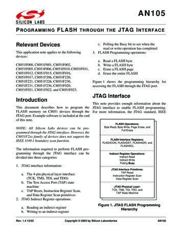
AN105P ROGRAMMING FLASH TH ROU GH TH E J TA G I NTERFACERelevant DevicesThis application note applies to the followingdevices:C8051F000, C8051F001, C8051F002,C8051F005, C8051F006, C8051F010, C8051F011,C8051F012, C8051F015, C8051F016,C8051F017, C8051F206, C8051F220,C8051F221, C8051F226, C8051F230,C8051F231, C8051F236, C8051F020,C8051F021, C8051F022, and C8051F023.c. Polling the Busy bit to see when theread or write operation has completed3. FLASH Programming operations:a.b.c.d.Read a FLASH byteWrite a FLASH byteErase a FLASH pageErase the entire FLASHFigure 1 shows the programming hierarchy foraccessing the FLASH through the JTAG port.JTAG InterfaceIntroductionThis note provides enough information about theThis document describes how to program the JTAG interface to enable FLASH programming.FLASH memory on C8051 devices through the For more information, the JTAG standard, IEEEJTAG port. Example software is included at the endof this note.NOTE: All Silicon Labs devices can be programmed through the JTAG interface. However, theC8051F2xx family of devices does not support theIEEE 1149.1 boundary scan function.The information required to perform FLASH programming through the JTAG interface can bedivided into three categories:1. JTAG interface information:a. The 4-pin physical layer interface(TCK, TMS, TDI, and TDO)b. The Test Access Port (TAP) statemachinec. TAP Reset, Instruction Register Scan,and Data Register Scan primitives2. JTAG Indirect Register operations:a. Reading an indirect registerb. Writing to an indirect registerRev. 1.4 12/03FLASH Operations:Byte Read, Byte Write, Page Erase, andFull EraseFLASH Interface Registers:FLASHCON, FLASHDAT, FLASHADR, andFLASHSCLIndirect Register Operations:Indirect ReadIndirect WritePolling BusyJTAG Interface Primitives:TAP ResetInstruction Register ScanData Register ScanJTAG Physical Layer:TCK, TMS, TDI, TDO, andTAP State MachineFigure 1. JTAG FLASH ProgrammingHierarchyCopyright 2003 by Silicon LaboratoriesAN105
AN1051149.1-1990, can be obtained from the Institute ofElectrical and Electronics Engineers (for information, see http://standards.ieee.org). The JTAG interface on C8051 devices is fully compliant with theIEEE 1149.1 specification. Those already familiarwith JTAG can skip to the section titled "Instruction Register on C8051 Devices‚" on page 7.Test Access Port (TAP) InterfaceThe hardware interface to the JTAG port consists offour signals, as shown in Figure 2:C8051FxxxTCKTMSTDITDOFigure 2. TAP Interface1. TCK input shift clock. Data is sampled at TMSand TDI on the rising edge of TCK. Data is output on TDO on the falling edge of TCK.2. TMS input mode select. TMS is used to navigate through the TAP state machine.3. TDI input. Input data to the Instruction Register (IR) or the Data Register (DR) is presentedto the TDI input, and sampled on the risingedge of TCK.4. TDO output. Output data from the InstructionRegister or the Data Register is shifted outTDO on the falling edge of TCK.2Rev. 1.4
AN105TAP State MachineThe primary purpose of the Test Access Port statemachine, which is shown in Figure 3, is to selectwhich of two shift registers, the Instruction Register or the Data Register, to connect between TDIand TDO. In general, the Instruction Register isused to select which Data Register to scan. Thenumbers next to the arrows in the diagram refer tothe logic state of TMS at the time TCK is broughthigh.1Test LogicReset001SelectDR ScanRun Test/IdleSelectIR Scan100Capture DR11Capture IR0000Shift DRShift IR11111Exit1 DRExit1 IR0000Pause DRPause IR110Exit2 DR11Update DR10Exit2 IRUpdate IR010Figure 3. TAP State MachineRev. 1.43
AN105TAP ResetThe TAP logic is reset by holding TMS high (logic'1') and strobing (bringing high and then back low)TCK at least five times, as shown in Figure 4.TCKTMSTDITDORun-Test/IdleTest Logic Reset?Figure 4. TAP Reset TimingThis advances the state machine to the Test LogicReset state from any state in the TAP statemachine, which resets the JTAG port and test logic.It does not reset the CPU or peripherals.TAP Notes:1. Data is valid on TDO beginning withthe falling edge of TCK on entry intothe Shift DR or Shift IR states.TDO goes “push-pull” on this TCKfalling edge and remains “pushpull” until the TCK rising edge.2. Data is not shifted on entry intoShift DR or Shift IR.3. Data is shifted on exit of Shift IRand Shift DR.4Rev. 1.4
AN105IR and DR ScanRegister is transferred in the Shift IR state. Duringa Data Register Scan operation, the Data Register isIn addition to test logic reset, there are two primi- transferred in the Shift DR state. Data is alwaystive operations that the state machine controls: shifted LSB-first.Instruction Register (IR) Scan, and Data Register(DR) Scan. In a scan operation, data is sampled at In C8051 devices, the Instruction Register isTDI on the rising edge of TCK, and is output on always 16 bits in length. The length of the DataTDO on the falling edge of TCK. During an Register varies, depending on the register selected.Instruction Register Scan operation, the IR10 IR11 IR12 IR13 IR14 -ScanRun-Test/IdleFigure 5. Instruction Register Scan TimingFigure 5 shows a timing diagram for an InstructionRegister access.TCKTMSTDIDI0TDODI1DI2DI3DI4DInDO0 DO1 DO2 DO3 Test/IdleFigure 6. Data Register Scan TimingFigure 6 shows timing for a Data Register access.Rev. 1.45
AN105IDCODE ExampleTo better illustrate how a typical JTAG operationworks, we present an example access, in this case,reading the IDCODE register.Reading the IDCODE is a two-step process. First,an Instruction Register Scan operation is initiated,and the Instruction Register is loaded with theIDCODE address, 16-bits shifted on TDI, as shownin Figure 7. Once the Instruction Register has beenloaded, a Data Register Scan operation is initiated,and the 32-bit IDCODE is read from the device, onTDO, as shown in Figure 8.Instruction Register 0x1004 for IDCODE scanTCKTMSTDIIR0IR1IR2IR3IR4IR5IR6IR7IR8IR9IR10 IR11 IR12 IR13 IR14 re 7. Instruction Register Scan Timing for IDCODE ReadData Register reads '0x10000243' for IDCODE scan on C8051F000 rev DTCKTMSTDITDODR0DR1DR2DR3DR4DR5DR6DR7DR8DR9 DR10 DR11 DR12 DR13 DR14 DR15 DR16 DR17 DR18 DR19 DR20 DR21 DR22 DR23 DR24 DR25 DR26 DR27 DR28 DR29 DR30 DR31Rev. DRSelect-DR-ScanRun-Test/IdleFigure 8. Data Register Scan Timing for IDCODE Read
AN105Instruction Register on C8051DevicesTable 3. DRAddress DecodingRegisterThe Instruction Register (IR) on C8051 devices isalways 16-bits in length, and is decoded as follows:11:0StateCntlDRAddressThe StateCntl field controls the state of the debughardware. In a FLASH programming operation,the system is first Halted, and then the CPU core isheld in Suspend mode to bypass the Watchdogtimer.Table 2. StateCntl DecodingStateCntl*Device State0000Normal0001Halt0010System Reset0100CPU Core Suspend1111Normal*unlisted states are reservedTable 3. DRAddress DecodingRegister*unlisted states are reservedIndirect RegistersTable 1. Instruction Register Decoding15:12DRAddress*The four FLASH registers (FLASHCON, FLASHADR, FLASHDAT, and FLASHSCL) areaccessed using a common indirect method. Thisindirect scheme handles the information transferbetween the JTAG clock domain, controlled byTCK, and the CPU clock domain, controlled bySYSCLK. These FLASH indirect registers are notto be confused with the standard 8051 indirect registers R0 and R1.Overview of Indirect RegisterAccessesTo read or write to an indirect register, the Instruction Register is first loaded with the proper DRAddress. Reads and writes are then initiated bywriting the appropriate Indirect Operation Code(IndOpCode) to the selected data register. On awrite, the Write opcode is followed by the data tobe written.The format for the data register for the incomingcommands is as follows:Table 4. Indirect Write DR DR0x084FLASHSCL0x08519:1817:0IndOpCodeWriteDataThe Indirect Operation Code (IndOpCode) bits aredecoded as follows:Table 5. IndOpCode DecodingIndOpCodeRev. 1.4Operation0xPoll10Read7
AN105Table 5. IndOpCode DecodingIndOpCode11available for reading. Figure 9 shows a flow chartthat describes how to perform a read operation onan indirect register.OperationWriteIndirect WriteThe format for the data register for outgoing data isThe Write operation initiates a write of WriteDataas follows:to the register selected by DRAddress. Registers ofany width up to 18 bits can be written. If the regisTable 6. Indirect Read DR Formatter to be written contains fewer than 18 bits, Write1918:10Data should be left-justified (MSB occupies bit17). This allows shorter registers to be written in0ReadDataBusyfewer JTAG clock cycles. For example, a write toan 8-bit indirect register can be accomplished byshifting only 10 bits (2-bit Write opcode 8 dataIndirect ReadThe Read operation initiates a read from the register selected by DRAddress. Reads can be initiatedby shifting only two bits into the indirect register(the Read IndOpCode bits). After the Read operation is initiated, the Busy bit is polled to determinewhen the operation has completed and the data isIndirect ReadLoad IR with register to be readIR 4xxxhxxx DRAddressLoad DR with 'Read' op codeDR 10b (2 bits)Poll Busy in DRDR 0b (1 bit)Busy10Read DRDR 0 (n 1 bits)n size of indirect registerFinishFigure 9. Indirect Read Flow Chart8Rev. 1.4
AN105bits). After a write is initiated, the Busy bit shouldbe polled to determine when the operation hascompleted. Figure 10 shows a flow chart describing how to perform a write operation on an indirectregister.Polling BusyThe Busy bit indicates that the current read or writeoperation has not completed. It goes high (‘1’)when an operation is initiated and returns low (‘0’)on completion. Because the Busy bit occupies theLSB of the returned data, polling for Busy can beaccomplished in one DR shift cycle (on exit of theShift DR state).On an Indirect Read, once Busy has gone low, theReadData can be shifted out. Note that the ReadData is always right-justified. This allows registersless than 18-bits to be read in fewer JTAG clockcycles. For example, an 8-bit Read can be performed in 9 DR shifts (8 data bits 1 Busy bit).Figure 11 shows the Data Register Scan timing forpolling the Busy bit.The contents of the Instruction Register should notbe altered when a Read or a Write operation is inprogress.Indirect WriteLoad IR with register to bewrittenIR 4xxxhxxx DRAddressLoad DR with 'Write' op codeand data to be writtenDR 11yyyyb (2 n bits)yyyy WriteDataTCKTMSTDIPoll Busy in DRDR 0 (1 bit)TDORun-Test/IdleUpdate-DRExit1-DRFigure 10. Indirect Write Flow est/IdleBusyBusyFigure 11. DR Scan Timing for Pollingthe Busy BitRev. 1.49
AN105FLASH ProgrammingTable 9. WriteMode DecodingWriteMode*Operation0010Initiate page erase oncurrent page if FLASHDAT 0xA5;Initiate erase of entireFLASH if FLASHDAT 0xA5 and FLASHADR isset to the address of theFLASH Read Lock Byteor the FLASH Write/Erase Lock Byte.FLASH Register DescriptionsThe FLASH is accessed through four indirect registers: FLASHCON, FLASHADR, FLASHDAT,and FLASHSCL. Each of these registers isaccessed using Indirect Read and Indirect Writeoperations as outlined in the previous section.FLASHCONFLASHCON is an 8-bit register that controls howthe FLASH logic responds to reads and writes to *unlisted states are reservedthe FLASHDAT register. The FLASHCON registercontains a ReadMode setting and a WriteMode FLASHADRsetting, decoded as follows:Table 7. FLASHCON Decoding7:43:0WriteModeReadModeTable 8. ReadMode DecodingReadMode*Operation0000FLBusy Polling0010Initiate FLASH read;Increment FLASHADRFLASHADR is a 16-bit register that contains theaddress of the FLASH byte to be read or written.FLASHADR is automatically incremented on completion of a read or a write operation.FLASHDATFLASHDAT is a 10-bit register containing 8-bits ofdata, an FLFail bit, and an FLBusy bit, as shownbelow:Table 10. FLASHDAT Read Decoding*unlisted states are reservedTable 9. WriteMode DecodingWriteMode*Operation0000FLBusy Polling0001Initiate FLASH Write;Increment FLASHADR9:210FLDataFLFailFLBusyA write to FLASHDAT need only consist of 8 bitsbecause the last bit latched assumes the MSB position.A read of FLASHDAT requires 11 DR SHIFTcycles (8 for FLData, 1 for FLFail, 1 for FLBusy,and 1 for Busy).Polling for FLBusy requires at least 2 DR SHIFTcycles, 1 for FLBusy and 1 for Busy.10Rev. 1.4
AN105FLASHSCLDisabling the Watchdog Timer (WDT)FLASHSCL is an 8-bit register that sets the prescale value required for deriving the timing forFLASH operations. When operating from the internal 2 MHz system clock, this register should beconfigured with 0x86 as follows:A flow chart showing the process for disabling theWatchdog timer is shown in Figure 12. The procedure is as follows:1. The system is reset by loading the InstructionRegister (IR) with 0x2FFF.Table 11. FLASHSCL Configuration7:43:0100001102. An IDCODE scan is performed by loading IRwith 0x1004, followed by a 32-bit DR scanwith 0x00000000.3. All following IR addresses set StateCntl to'0x4', which keeps the core in SUSPEND mode,and takes the FLASH off-line.Before the FLASH can be programmed, the deviceneeds to be reset and the Watchdog timer taken offline. Otherwise, the Watchdog timer may initiate asystem reset during a FLASH operation, resultingin undefined behavior.FLASH Access ProceduresDisable WDTExecute system RESETIR 2FFFhRead ID CodeIR 1004hDR 0 (32-bits)FinishFigure 12. Flow Chart for Bypassing theWatchdog TimerRev. 1.411
AN105Reading a FLASH Byte1. Load FLASHSCL with 0x86, to set properFLASH timing using the internal 2 MHz system clock. This is accomplished by an IndirectFigure 13 shows a flow chart which illustrates howWrite of 0x86 to FLASHSCL.to read a FLASH byte. The procedure is as follows:2. Load FLASHADR with the 16-bit address to beread. This is accomplished with an IndirectWrite of 16-bits to FLASHADR.FLASH Read3. Load FLASHCON with code to initiate a read(0x01). This is accomplished with an IndirectWrite of 8-bits to FLASHCON.Load FLASHSCL with 0x86:Indirect Write (0x4085, 0x86)4. Initiate the read by reading FLASHDAT. Thisis an Indirect Read of 0-bits (the DR scan consists of only the 2-bit read op-code). Note thatthis merely starts the FLASH read process.Load FLASHADR with addressto read:Indirect Write (0x4084, yyyy)yyyy 16-bit addressLoad FLASHCON with 'InitiateRead' code:Indirect Write (0x4082, 0x02)5. Load FLASHCON with the code to pollFLBusy (0x00); This is an Indirect Write of 8bits to FLASHCON.Initiate READ operation byreading FLASHDAT:Indirect Read (0x4083,0 bits)6. Poll FLBusy until it goes low, indicating thatthe read has completed. This is an Indirect Readof 1-bit. The DR Scan for polling FLBusy isshown in Figure 14.Load FLASHCON with 'PollFLBusy' code:Indirect Write (0x4082, 0x00)7. Read FLASHDAT. This is an Indirect Read of10-bits (8 data bits, 1 FLFail bit, and 1Poll for FLBusy:Indirect Read (0x4083, 1 bit)TCKFLBusy1TMSTDI0TDOBusy FLBusyRead FLASHDAT:Indirect Read (0x4083, 10 -DRyesSelect-DR-ScanRun-Test/IdleRead next address?noFinishFigure 13. Flow Chart for Reading aFLASH Byte12Figure 14. DR Scan Timing for PollingFLBusyRev. 1.4
AN105FLBusy bit). The DR Scan for readingFLASHDAT is shown in Figure 15.If a series of consecutive bytes are to be read, theprocess can be restarted again at step (3) above,since FLASHADR is automatically incrementedfollowing a read or a write operation.The FLFail bit is set to a ‘1’ if the read operationattempted to access a Read-locked sector.TCKTMSTDITDOBusy FLBusy ure 15. DR Scan Timing for FLASHDAT ReadRev. 1.413
AN105Writing a FLASH Byte1. Load FLASHSCL with 0x86, to set properFLASH timing for using the internal 2 MHzsystem clock. This is accomplished by an IndiFigure 16 shows a flow chart describing how torect Write of 0x86 to FLASHSCL.write a FLASH byte. The procedure is as follows:2. Load FLASHADR with the 16-bit address to bewritten.FLASH Write3. Load FLASHCON with the 'Initiate Write'opcode (0x10).Load FLASHSCL with 0x86:Indirect Write (0x4085, 0x86)4. Load FLASHDAT with the data to be written.This is an 8-bit Indirect Write.5. Load FLASHCON with the 'Poll FLBusy'opcode (0x00).Load FLASHADR with addressto be written:Indirect Write (0x4084, yyyy)yyyy 16-bit address6. Poll FLBusy. This is accomplished by initiating 1-bit Indirect Reads on the FLASHDATregister.Load FLASHCON with 'InitiateWrite' code:Indirect Write (0x4082, 0x10)If a series of consecutive bytes is to be written, theprocess can repeat, starting at step (3) above. FLASHADR is automatically incremented at the end ofa read or a write operation.Load FLASHDAT with the datato be written:Indirect Write (0x4083, zz)zz 8-bit data to be writtenThe FLFail bit is set to a ‘1’ if the write operationattempted to write to a Write-locked sector.Load FLASHCON with 'PollFLBusy' code:Indirect Write (0x4082, 0x00)Poll for FLBusy:Indirect Read (0x4083, 1 bit)FLBusy?10yesWrite next address?noFinishFigure 16. Flow Chart for Writing aFLASH Byte14Rev. 1.4
AN105Figure 17 shows the DR Scan timing for the 8-bitwrite to FLASHDAT, step (4) above.Erasing a FLASH PageThe FLASH memory is organized as a series of512-byte pages. The procedure for erasing aFLASH page is similar to writing a FLASH byte,except that the FLASHCON register needs to be setto 0x20, and FLASHDAT needs to be set to 0xA5.FLASHADR can be set to any address within thepage to be erased. If FLASHADR is set to either ofthe Lock Byte addresses (0x7dfe or 0x7dff on‘F0xx devices and 0x1dfe or 0x1dff on the ‘F2xxdevices), then the erase operation initiates an eraseof the entire FLASH memory.Unlike read and write operations, FLASHADR isnot automatically incremented at the end of /IdleFigure 17. DR Scan Timing for a FLASHDAT WriteRev. 1.415
AN105erase operation. Figure 18 shows a flow chart forthe FLASH page erase procedure.FLASH PageEraseLoad FLASHSCL with 0x86:Indirect Write (0x4085, 0x86)Load FLASHADR with addressin page to erase:Indirect Write (0x4084, yyyy)yyyy 16-bit addressLoad FLASHCON with 'InitiateErase' code:Indirect Write (0x4082, 0x20)Initiate ERASE operation bywriting '0xA5' to FLASHDAT:Indirect Write (0x4083,0xA5)Load FLASHCON with 'PollFLBusy' code:Indirect Write (0x4082, 0x00)Poll for FLBusy:Indirect Read (0x4083, 1 bit)FLBusy?10FinishFigure 18. Flow Chart for Erasing aFLASH Page16Rev. 1.4
AN105Programming a Device in aJTAG Chainister (DR) scan to collect each device’s identification number. If a device does not support theIDCODE instruction, then it is assigned an ID ofIf the C8051 device participates in a boundary scan 0x00000000.chain with other devices or the JTAG ports of multiple C8051 devices are connected as shown in The Instruction Register discovery process beginsFigure 19, the device can be isolated and pro- with a JTAG Reset operation. During the followgrammed using methods discussed in this note. A ing IR Scan operation, ones are shifted into thesoftware example of programming the FLASH of a TDI pin on the last device in the chain (Device #2device in a JTAG chain is included at the end of in Figure 19, for example). The IR discovery process ends when a ‘11’ pattern is received from thethis note.TDO pin of the first device in the JTAG chain(Device #2 in Figure 19). An input of ‘10’ signifiesDiscovering an Unknown JTAG that a new device has been encountered. Figure 20shows the state machine used for analyzing theChainThe purpose of the discovery process is to collect inputs in a discovery IR scan.information about the devices connected in thechain. The discovery process assumes that allTDO 0S01Resetinstruction registers have a ‘1’ in the LSB and ‘0’sin all other bit positions. This is true for all SiliconLabs devices, but may not be true for all JTAGErrorS1devices. Also, upon reset, the optional 32-bit1IDCODE register is selected by default. If the0device does not have an IDCODE register, the 1-bit1BYPASS register is selected instead. In the softS2End ofNew Device/ware example, the discovery process uses theseChainCountingZerosassumptions to record information about the0devices connected in the chain.Figure 20. IR Discovery State MachineThe discovery process is divided into two parts, anInstruction Register (IR) scan to determine the After the IR scan is complete and the JTAG statenumber of devices in the chain and the length of machine is reset, the discovery process issues a DReach device’s Instruction Register, and a Data Reg- scan to read and store the IDs of the devices forTCKTMSTDOTDIJTAG ControllerTCKTDOTMSTDIJTAG Device #0TCKTDOTMSTDIJTAG Device #1TCKTDOTMSTDIJTAG Device #2Figure 19. Typical JTAG Chain ConnectionRev. 1.417
AN105future reference. From the JTAG specification, the IR and DR Scans in JTAGLSB returned on a DR scan will be a ‘1’ if theChainsdevice supports the IDCODE instruction and a ‘0’if the device is instead in BYPASS mode. Figure 21 Each Instruction Register scan operation is configshows how the DR scan determines each device’s ured to place all devices other than the device to beprogrammed in BYPASS mode. This is accomidentification number.plished by shifting ‘1’s into the Instruction Registers of all devices before and after the isolatedDiscoveryDR Scandevice, as shown in Figure 22.Reset the JTAG Logic.(The IDCODE or the BYPASSregister is automatically selected.Data Register scan operations pad one bit for eachdevice before the device to be programmed and onebit for each device after the device to be programmed to account for the BYPASS registers ofthese devices.Initiate DR SCAN.Get an Input from the TDO pin1. IR Scan operations are prefixed with m ‘1’s andpost-fixed with n ‘1’s, where m is the number ofinstruction register bits before the device to beprogrammed and n is the number of instructionregister bits after the device to be programmed,as shown in Figure 22.Input?10Device does not have an ID.Assign ID 0x00L.Device has an ID.Shift in the next 31bits.Last Device?2. DR Scan operations are prefixed with x ‘0’s andpost-fixed with y ‘0’s where x is the number ofJTAG devices before the device to be programmed and y is the number of JTAG devicesin the chain after the device to be programmed.noyesDoneIsolating a DeviceFigure 21. Flow Chart for Discoveringthe Device IDsTDOTo be able to program a device in a chain, thedevice must be isolated. An isolated device is theonly one not in BYPASS mode. This allows onlyone device to be accessed at a time. There are fourvariables that the IR scan and DR scan operationsInstruction RegisterInstruction RegisterInstruction Register11.10x4yyy11.1Data RegisterData RegisterData Register0xxxx0Device in BYPASS modeDevice being programmedDevice in BYPASS modeFigure 22. Isolating a C8051 Device to be Programmed18Rev. 1.4TDI
AN105use to determine how many ‘1’s or ‘0’s to pad withwhen issuing a scan, as follows:Table 12. Variables Required whenIsolating a Device in a JTAG Chain.For the IR Scan operations:number of IR bits before the isolated devicenumber of IR bits after the isolated deviceFor the DR Scan operations:number of devices before the isolated devicenumber of devices after the isolated deviceIn the software example, the JTAG Isolate() procedure accepts the index of the device to be isolatedand sets these variables accordingly. After the procedure is called, all the following IR and DR scansare performed on the device specified by the index.To execute a scan operation on another device, theJTAG Isolate() procedure must be called with anew index prior to issuing the scan. If there is onlyone device in the chain, then neither the JTAG Isolate() nor the JTAG Discover() procedures need tobe called prior to issuing a scan.FLASH OperationsFLASH operations for a JTAG chain are the sameas for a single device except that the device undertest must be isolated before calling the FLASHOperations.Rev. 1.419
AN105Software Examples For the ‘F00x, ‘F01x, and ‘F2xx SeriesProgramming a Single JTAG -----------------------------------------// JTAG ------------------------------------------// This program contains some primitive routines which read, write, and erase the FLASH// through the JTAG port on a C8051Fxxx device under test (DUT). The JTAG pins on the// DUT are connected to port pins on the C8051F000 master device.//// Target device: C8051F000, C8051F010//// Tool chain: KEIL Eval --------------------------------------------// e c8051f000.h // SFR -----------------------------------------------// Global D P1 6;// green LED: ‘1’ ON; ‘0’ OFF// GPIO pinssbitTCK sbitTMS sbitTDI sbitTDO #define#defineconnecting to JTAG pins on device to beP3 7;// JTAGP3 6;// JTAGP3 5;// JTAGP3 4;// JTAGprogrammed (DUT)Test ClockMode SelectData InputData OutputTRUE 1FALSE 0// JTAG Instruction Register Addresses#defineINST LENGTH 16// number of bits in the// Instruction fff0x00000x0002#defineRESET0x2fff// System RESET Instruction#define#defineIDCODEIDCODE LEN0x100432// IDCODE Instruction address/HALT// number of bits in the ID code#define#defineFLASHCONFLCN LEN0x40828// FLASH Control Instruction address// number of bits in FLASHCON#define#define#defineFLASHDATFLD RDLENFLD WRLEN0x4083108// FLASH Data Instruction address// number of bits in an FLASHDAT read// number of bits in an FLASHDAT write#define#defineFLASHADRFLA LEN0x408416// FLASH Address Instruction address// number of bits in FLASHADR20Rev. 1.4
AN105#define#defineFLASHSCLFLSC LEN0x40858// FLASH Scale Instruction address// number of bits in -------------------------------------------// Function ---------------------------------------------void init (void);void JTAG StrobeTCK (void);void JTAG Reset (void);unsigned int JTAG IR Scan (unsigned int instruction, int num bits);unsigned long JTAG DR Scan (unsigned long dat, int num bits);void JTAG IWrite (unsigned int ireg, unsigned long dat, int num bits);unsigned long JTAG IRead (unsigned int ireg, int num bits);int FLASH ByteRead (unsigned int addr, unsigned char *pdat);int FLASH ByteWrite (unsigned int addr, unsigned char dat);int FLASH PageErase (unsigned int -----------------------------------------// MAIN Routinevoid main (void) {unsigned long id;unsigned char dest;int pass;id 0x12345678L;init ();// initialize portsJTAG Reset ();// Reset the JTAG state machine on DUTJTAG IR Scan (RESET, INST LENGTH);// Reset the DUTJTAG IR Scan (IDCODE, INST LENGTH);id JTAG DR Scan (0x0L, IDCODE LEN);////////load IDCODE into IR and HALT the DUTread the IDCODEIDCODE should 0x10000243 forC8051F000 rev D device// here we erase the FLASH page 0x1000 - 0x11ff, read 0x1000 (it’s an 0xff),// write a 0x66 to 0x1000, and read 0x1000 again (it’s changed to an 0x66).while (1) {pass FLASH PageErase (0x7c00);// erase page prior to writing.while (!pass);// handle Write Lock conditiondest 0x5a;// set test variable to non-0xff valuepass FLASH ByteRead (0x7c00, &dest);while (!pass);// dest should return 0xff// handle Read Lock conditiondest 0x66;pass FLASH ByteWrite (0x7c00, dest);while (!pass);// store 0x66 at 0x1000// handle Read Lock conditionpass FLASH ByteRead (0x7c00, &dest);while (!pass);// dest should return 0x66// handle Read Lock conditionpass FLASH PageErase (0x7c00);Rev. 1.421
AN105while (!pass);pass FLASH ByteRead (0x7c00, &dest);while ---------------------------------------------// Functions and ------------------------------// ---------------------------------------// This routine disables the watchdog timer and initializes the GPIO pins//void init (void) {WDTCN 0xde;WDTCN 0xad;// disable watchdog timerXBR2 0x40;PRT1CF 0x40;PRT3CF 0xe0;P3 & 0x1f;////////enable crossbarenable P1.6 (LED) as a push-pull outputmake P3.7-5 push-pull outputsTCK, TMS, and TDI all ---------------------------------------// JTAG --------------------------------------------// This routine strobes the TCK pin (brings high then back low again)// on the target system.//void JTAG StrobeTCK (void) {TCK 1;TCK --------------------------------------// JTAG ----------------------------------------// This routine places the JTAG state machine on the target system in// the Test Logic Reset state by strobing TCK 5 ti
b. The Test Access Port (TAP) state machine c. TAP Reset, Instruction Register Scan, and Data Register Scan primitives 2. JTAG Indirect Register operations: a. Reading an indirect register b. Writing to an indirect register c. Polling the Busy bit to see when the read or write operation has completed 3. FLA