Transcription
INSTRUMENT STAGECHECK ORAL GUIDE(REVISION I)
REFERENCESFAR/AIMAC 00-45GAC 00-6AIPHPHAKIFHPOHRECOMMENDED READINGS
Selected Advisory Circulars120-57 Surface Movement Guidance Control System120-91 Airport Obstacle Analysis90-100 RNAV Operations20-138 Airworthiness of Navigation Systems120-71 SOP for flight deck crew members90-101 RNP certification97-1RVR
Certificates and DocumentsHow long is your pilot certificate valid? (61.19 c)Your pilot certificate is issued without a specific expiration dateWhat privileges and limitations apply to you as a private pilot? (61.113) (91.146)Privileges – Act as PIC and carry passengers – conduct search and rescue operations; flyfor charitable, non-profit, or community event; act as an aircraft salesman if you have atleast 200 hours.Limitations – Cannot fly for hire; must pay no less than pro rata shareWhat documents must you have with you to fly the airplane? (61.3)Pilot certificate, medical certificate, and government issued photo IDHow long is a medical certificate valid for? (61.23)Under 40
40 and OlderHow do we keep our pilot certificate current? (61.56, 61.57)Student pilot: with valid medical certificatePPL: Flight review every 24 calendar monthsWhat are the currency requirements for carrying passengers? (61.57)3 take offs and landings within the preceding 90 days in an aircraft of the same category,class and type if required. At night, these 3 landings must be made to a full stop.Night definition? When can you perform required night landings? (1.1, 61.57)Night the time between evening civil twilight and morning civil twilightNight landings can be logged 1 hour after sunset to 1 hour before sunrise.When is an instrument rating required? (61.3 (v)(e) 91.157 (4) (i) (ii))In Class A airspaceOperating under IFRAnytime the weather is beneath VFR minimums: Ceiling below 1000’ or visibility lessthan 3 miles
Anytime you are operating special VFR at nightWhat are the recency-of-experience requirements to be PIC of a flight under IFR?(61.57c)Within the preceding 6 months of the flight, 6 instrument approaches and holdingprocedures and intercepting and tracking courses must be completed either in actual IMC,in VMC while using a view limiting device, or in a flight simulator/FTD.Define “appropriately rated safety pilot.” (91.109)The safety pilot must possess at least a private pilot certificate with the category and classratings appropriate to the aircraft being flown and he/she must have adequate visionforward and to each side of the aircraft.If a pilot allows his/her instrument currency to expire, what can be done to becomecurrent again? (61.57)If you fail to meet the instrument experience requirements for more than 6 months, theonly way to reestablish currency is with an IPC.What aircraft/instruments/equipment are required for IFR operations?ATOMATOFLAMES, FLAPS, and GRABCARD (91.205)Generator/alternatorRadioAltimeter (adjustable)Ball (inclinometer)Clock w/ hours, minutes, and secondsAttitude indicatorRate of turn indicatorDirectional gyro*DME is required at or above FL240 if VOR navigation is requiredWhat are the required tests and inspections of aircraft and equipment to be legal forIFR flight? AVIATESAnnual – every 12 calendar months (91.409)VOR – every 30 days for IFR (91.171)100 hour if airplane is being operated for hire (91.409)
Altimeter/Pitot Static – 24 calendar months; required for IFR flight (91.411)Transponder – 24 calendar months (91.413)ELT – 12 calendar months or after 1 hour cumulative use or half of battery life (91.207)Service bulletins and ADs complied with (PHAK 8-12)What are the different methods for checking the accuracy of VOR equipment?(91.171) (IPH 2-29) VGAADVOTGround CheckAirborneAirwayDual VORWhat records must be kept concerning VOR checks?Date, place, bearing error, and signatureWhere can you find the location of airborne, ground and VOT testing stations?Chart Supplement (see back cover)What documents need to be on board an aircraft to make it legal for IFR flight?ARROW (91.9, 91.203)Airworthiness CertificateRegistrationRadio License (required for international flight)Operating Limitations (found in the POH)Weight and Balance equipment list
Aircraft Systems (PHAK Chapter 7) (IFH Chapter 5) (POH)Describe the pitot-static flight instrumentsAirspeed Indicator – This is the only instrument that uses both the pitot and static ports.It measures the difference between dynamic pressure (ram air entering the pitot tube) andstatic pressure (air that is unaffected by the aircraft’s flight path). Ram air exerts a forceon a diaphragm inside of the instrument. The instrument case is full of static air.Altimeter – This measures the difference between static pressure inside of the instrumentcase and standard pressure (29.92” Hg) sealed inside of an aneroid wafer. When theairplane is climbing and ambient pressure begins to decrease, the wafer is able to expandbecause the air that is sealed inside is now of higher pressure. The altimeter is a sensitivealtimeter meaning that it can be calibrated to the local barometric pressure by adjustingthe Kollsman window.
VSI – Measures the difference between static pressure and static pressure that is subjectto a calibrated leak approximately every 6-9 seconds.How do the pitot- static instruments respond to blockages?*Note the very first error – this error would be highly uncommon in the Piper Archerbecause there is no drain hole on the pitot mast like most other training aircraft. If thereis a blockage in the pitot mast, the drain hole would more than likely be unaffected.
Describe the gyroscopic instrumentsThe Gyroscopic instruments are powered by an engine driven vacuum pump with theexception of the turn coordinator which is electrically powered. The two principles thatgyroscopes operate off of are:
Rigidity in space: while spinning, a gyroscope will tend to stay fixed in its plane ofrotation. Think of a bicycle wheel. With enough momentum, you are able to stay naturallybalanced.Precession: when a force is applied to a gyroscope, the resultant force is felt 90 aheadin the direction of the rotation.Attitude Indicator – Rotates in the horizontal plane and operates off of the principle ofrigidity in space. The aircraft pitches and rolls around the erect gyroscope. The effects ofprecession are not felt because pendulous vanes attached to the base of the gyro duct highpressure air from the vacuum through small doors that open and close by the force ofgravity to keep the gyro in its original position.Heading Indicator – Rotates in the vertical plane and operates off of rigidity in space aswell. As the aircraft yaws around the gyro, a gear inside of the instrument case rotates thecompass card to show the magnetic direction. Precession caused from aircraft movementand friction causes error that must be corrected by resetting the heading indicator to themagnetic compass approximately every 15 minutes.Turn Coordinator – This electrically powered gyro rotates in the vertical plane and it usesprecession to measure rate of turn and rate of roll. When the aircraft yaws, the gyroprecesses and the airplane on the face of the instrument indicates the direction and rate ofthe turn. Notice in the diagram of the instrument that it is slightly canted upwards. This isso rate of roll can be indicated as well. When the aircraft begins a bank the aircraft willalso indicate the direction of the bank. If it is a rapid roll the airplane will respond by
banking more steeply. Once the turn is established it will properly indicate the rate of theturn.What is the difference between the turn coordinator and the turn and slipindicator?How does the vacuum system operate? (PHAK 7-17) (POH 7-17) (IFH 5-17)An engine driven vacuum pump creates suction. Air is pulled through a filter and thendirected to the instrument case. Rotor vanes on the gyros catch the air like a water wheeland cause it to rotate at a high speed. In the Archer IIIs, there is also an electrical vacuumpump to be used as a backup.Explain the errors associated with the magnetic compass.Variation – Since the magnetic north pole and the geographic North Pole are notcollocated, we need to consider this when planning flights. Easterly variation issubtracted from true heading while westerly variation is added to get our magneticheading. Remember: East is least and West is best!Deviation – Since a compass depends on aligning with the Earth’s magnetic fields to readaccurately, any kind of other local magnetic fields will cause an error known as deviation.This other magnetic fields are produced from electrical currents from the aircraft avionicsand varies on different headings. The compass correction card located on the compasstells the pilot which compass heading to steer to for a desired magnetic heading.
Dip Errors – While flying on a north or south heading, these turning errors are mostpronounced. While flying a north heading and turning to the left, the compass willinitially show a turn in the opposite direction and lag behind the turn. When on a southheading, the compass will lead the turn and show that the turn is being made a muchfaster rate than it actually is.*Imagine that north is home to the compass. While at “home” the compass wants to staythere during a turn and will lag behind before it finally decides to catch up reluctantly.Conversely, while most far away from home on a south heading, when a turn iscommenced, the compass gets excited and races there (leading the turn)Northerly Turning Error – CG displacement of the float assembly in the compass causesfalse turn indications. When turning to the north, the turn should be stopped prior toarrival at the desired heading. When turning south, turn pass the desired heading. Therule is: UNOS Undershoot North Overshoot SouthAcceleration Error – While on east or west headings, acceleration results in a slight turnto the north. Deceleration results in a slight turn to the south. The rule is: ANDSAccelerate North Decelerate SouthOscillation Error – A combination of all of these errors and results in the compassswinging back and forth around the headings being flown
Navigational Equipment (AIM Chapter 1) (PHAK Chapter 15) (IFHChapter 9)What is an HSI? (IFH 5-15)The Horizontal Situation Indicator combines the functions of the heading indicator andthe VOR receiver into one instrument display. The major benefit is that most of thereverse sensing problems associated with a VOR receiver are precluded. This is becausewhen an HSI is tuned to a VOR station, a course deflection of left or right always mean
left or right notwithstanding the course you select with the course indicating arrow. Theexception is when flying a localizer backcourse. To avoid reverse sensing, the head of theneedle must be set to the localizer front course!Why doesn’t the HSI precess? (IFH 5-15)It makes use of the lines of flux associated with the Earth’s natural magnetic field. Thesehave two basic characteristics:1. Magnets align with these lines2. When a wire crosses them, an electrical current is inducedThe flux gate compass uses the second principle to drive gyros that slaved to its inputs. Aflux valve, which is a small segmented ring that accepts the lines of flux, is the directionsensing component of the system. It is located as far as possible away from the aircraft’slocal magnetic fields to ensure accurate indications (usually in the wingtip). Themagnetic slaving transmitter sends an electric signal to the HSI which operates a torquemotor to align the instrument with the appropriate magnetic heading.
What are the different classes of VOR stations? What are their service volumes?(AIM 1-1-8)What are the components of the VOR indicator instrument? (IFH 9-11)
How many degrees of deviation does each dot represent? What angular deviationfrom a VOR course is represented by half-scale deflection of the CDI? (IFH 9-11)Each dot represents 2 of deviation. Half scale deflection is 5 off course.How do you determine the VOR station is operating properly? (PHAK 15-25)1. Tune the appropriate VOR frequency2. Use the Ident. feature to listen to the associated Morse Code3. Make sure the NAV warning flag is not in viewWhat would happen if the VOR station were undergoing maintenance? (AIM 1-1-3)It may translate a Morse Code of TEST ( ‒ ‒ ) or the code may be removedentirelyWhat does it mean if there is only a single coded identification every 30 seconds on aVORTAC station? (AIM 1-1-7) (IFH 9-17)The VOR function is not working but the DME function is workingWhat are the limitations of a VOR (PHAK 15-26) (IFH 9-14)Line of sight only“Cone of confusion” – During passage of a station the aircraft is directly above the VORand this causes large needle deflections and momentary loss of signalPilot Error Failure to properly tune and identify Failure to check for accurate signal
Reverse sensing* To avoid reverse sensing, when towards a VOR you should always have a TOflag – when flying away from the station you should always have a FROM flag.In other words, the top of the heading indicator should always match the top ofthe VOR receiverWhat is DME? When is DME equipment required? (91.205 (e)) (AIM 1-1-7) (IFH 917)DME is distance measuring equipment. It is a separate ground station that may becollocated with a VOR, ILS, or localizer. It provides slant range distance in NM. Whenusing VOR navigation above 24000, DME or a suitable RNAV system is required.Do all VOR stations have the capability of providing distance information?VOR stations do not provide distance information by themselves. VOR/DMEs andVORTACs (VORs collocated with a TACAN) provide distance information.What is slant-range distance? To minimize slant-range error, how far from thefacility should you be and at what altitude? (IFH 9-19)Slant range distance is the actual distance between the aircraft and the ground station (asopposed to the horizontal distance). Altitude aircraft has a direct effect on slant rangeerror. This error will be minimized if the aircraft is at least 1 mile away from the stationfor every 1000’ of altitude.
How does GPS work? (AIM 1-1-17) (PHAK 15-32) (IFH 9-24)GPS is a space based navigation system as opposed to land based NAVAIDs such asVORs, DME, etc.Satellite constellation consists of 24 NAVSTAR satellites arranged in 6 orbital planes11,000 miles above the Earth.Arranged so that at least 5 satellites in view at all timesDistance is determined by the time it takes for radio signal to travel from satellite toaircraftPosition is triangulated from multiple satellites4 satellites are needed to determine a 3D position (latitude, longitude, and altitude)5 are needed for RAIMWhat is RAIM? (AIM 1-1-17)Receiver Autonomous Integrity Monitoring
The purpose is to determine the accuracy or “integrity” of the GPS signal. It does this bycomparing the signals from the 5 satellites. If there is a discrepancy RAIM gives you analert that the signal may not be reliable.There are 2 error messages you can potentially receive:1. A discrepancy or potential error has been detected2. There are not enough satellites in view to give you RAIMWhat is FDE? (AIM 1-1-17)Fault Detection and ExclusionRAIM detects an error but does nothing about it except give you a warning. FDE is afunction of some RAIM capable GPS. It requires 6 satellites so that info from the faultysatellite can be excluded.What is WAAS? (AIM 1-1-18) (IFH 9-32)Wide Area Augmentation SystemEnhances the GPS integrity and availability by:Incorporating wide-area ground reference stations to monitor the signal from the GPSsatellites.The information is sent to a master station where the correction occursThe corrected signal is a sent to a GEO (geostationary satellite) and is broadcast on thesame frequency as GPS to WAAS receivers.What are the requirements of using GPS for IFR? (AIM 1-1-17) (IFH 9-28)GPS must be certified by TSO-C129 (RAIM) or TSO-C145 or 146 (WAAS)The installation must be done in accordance with AC 20-138If not, then the GPS can only be used to enhance situational awareness but ACTIVEMONOTORING or an alternate navigation source is required.What are the benefits and limitations of RAIM capable GPS? (AIM 1-1-18 e. 2)(IFH 9-26) (IPH 1-12)As long as RAIM is assured, no requirement to ACTIVELY MONITOR othernavigational sources
Generally only provides lateral guidance (with the exception of Baro-Vnav equipment)Alternate airport must have an IAP other than GPS and those ground based NAVAIDSmust be monitoredRAIM is not guaranteed – signal could be lost due to1. Inadequate number of satellites in position at the airport2. Satellite malfunction3. Antenna location on the aircraft4. Changes in pitch or bank angleHow do we verify that we will have RAIM during the flight? (AIM 1-1-18)http://sapt.faa.gov/FSS Briefers can provide RAIM predictions for a 3 hour periodAlternatively, go to AUX page 3 on the GNS 430 and use the RAIM prediction toolWhat are the benefits of WAAS capable GPS? (AIM 1-1-18 e. 2) (IFH 9-26) (IPH 112 and 4-23)More precise than RAIMProvides lateral and vertical navigation without the temperature errors associated withBaro-VnavNo RAIM prediction necessaryAn airport that only has a GPS approach may be selected as an alternate*for flight planning purposes – only LNAV minimums can be consideredWhat are the components of the ILS? (AIM 1-1-9) (IFH 9-35)Visual: approach lighting system, VASI/PAPI, and precision approach runwayRange: marker beacons/compass locator and/or DMELateral and vertical guidance: localizer and glideslope
What are the distances from the threshold of the outer, middle and inner markers?(AIM 1-1-9) (IFH 9-37)Outer marker: 4-7 miles – usually at the glideslope intercept positionMiddle marker: 3500’ – represents the decision altitude (200’ above TDZE)Inner marker: Located between the MM and the landing threshold – represents the DHfor a CAT II ILS approachWhat are substitutes for an ILS outer marker? (91.175(k))Compass locators, DME, VOR, GPS, Precision Approach Radar (PAR), or AirportSurveillance Radar (ASR)What is the service volume of the localizer?Where is the localizer antenna array located (AIM 1-1-9 Figure 1-1-7)?The departure end of the runway aligned with the centerlineWhat is the course width of a localizer signal?Localizer courses vary between 3 and 6 so that at the landing threshold the total widthis 700’
What is the sensitivity differences between the CDI tuned to a VOR and a CDItuned to a LOC?Full scale deflection represents at least 10 when tuned to a VOR and only 2.5 whentuned to the localizer.What is the usable range of the glide slope?10nmWhere is the glideslope equipment located?Between 750’-1250’ from the approach end of the runway and 400-600’ to one side ofthe centerlineWhat are the dimensions of the glideslope course?The total width is 1.4 therefore full scale deflection represents at least .7 What errors is the ILS subject to?Reflection – Radio waves can bounce off of surface vehicles or other aircraft leading toerroneous indicationsFalse courses – Intercepting the GS at other than the published altitude can causeconfusion because the GS equipment inherently produces various courses at highervertical angles.What is a Simplified Directional Facility (SDF)? (AIM 1-1-10) (IFH 9-43) (IPH 4-88)It provides lateral guidance similar to a localizer but less accurate because the course isfixed to either 6 or 12 . The SDF antenna may be offset from the runway centerline butusually not by more than 3 . There is no vertical guidance.What is a Localizer Type Directional Aid (LDA) (AIM 1-1-9)More precise than an SDF because the course is usually between 3 - 6 just like alocalizer (hence, localizer type). An LDA may also provide a glideslope for verticalguidance in some instances. These are published as LDA/Glideslope and arecharacterized as APVs (approaches with vertical guidance).
So what makes this different from a localizer or ILS? An LDA is NOT aligned with therunway. Upon arriving at the MDA/DA, the pilot will have to maneuver the aircraft intoposition to make a normal landing. LDAs may have straight in minimums, however, ifthe alignment is within 30 of the runway centerline.IFR Departures (AIM Chapter 5) (IFH Chapter 10) (IPH Chapter 1)What are the elements of an IFR clearance?Clearance LimitRouteAltitudeFrequencyTransponder codeWhat is the minimum visibility needed to takeoff?There are no weather limitations for aircraft operating under Part 91. Standard takeoffminimums however are 1sm for aircraft having two engines or less.What are the 2 different types of departure procedures? (AIM 5-2-8)Obstacle Departure Procedure (ODP)Standard Instrument Departure (SID)Why are ODPs published? (AIM 5-2-8) (IFH 10-5) (IPH 1-14) (AC 120-91)The primary purpose is to provide the pilot with a means to get from the terminal area tothe en route structure while remaining clear of obstacles. There is an imaginary plane
called the 40:1 Obstacle Identification Surface. If an obstacle penetrates this plane thenthe following may happen:1. There will be a steeper than normal (200fpnm) climb gradient published2. Other than standard takeoff minimums will be published so that pilot can maintainvisual separation3. A specific departure route will be publishedWhat criteria determines that you will remain clear of obstacles when flying an ODP?1. Cross the departure end of the runway at or above 35’ AGL2. Make first turn no earlier than 400’ AGL (unless otherwise specified)3. Maintain climb gradient of at least 200fpnm (unless otherwise specified)What is the pilot’s responsibility concerning ODPs?1. Determine that an ODP has been published2. Determine whether or not to fly it even if not issued by ATC in a clearance. Pilots areencouraged to fly ODPs at night, in MVFR, and IFR conditions3. Determine aircraft performance is adequate for the procedure4. Be aware of low close-in obstaclesHow would you know if an ODP has published for an airport? (IFH 1-16)The T symbol in the notes section of an IAP means that the takeoff minimums are not standard.Refer to the takeoff minimums section of the TPPs for the new criteria and ODPs. ODPs arealways textual and sometimes graphic. Graphic ODPs will have (OBSTACLE) printed on them.How can you determine if your aircraft will be able to meet the required climb gradient?
Determine your aircraft’s rate of climb with the POH. Use the chart in the back of the TPPs toconvert it to climb gradient.Alternatively: 𝑅𝑎𝑡𝑒 𝑜𝑓 𝐶𝑙𝑖𝑚𝑏 𝑔𝑟𝑜𝑢𝑛𝑑𝑠𝑝𝑒𝑒𝑑60x climb gradientWhat are low close-in obstacles?Obstacles that are located within 1nm of the departure end of the runway that penetrate the 40:1OCS. Avoidance can be assured by early liftoff or visually. The obstacle location and theirheights are contained in the notes section of the takeoff minimums in the TPPs.What does VCOA mean? When would this option be published? (IPH 1-38)A visual climb over airport allows the pilot to climb while circling to get to a safe altitude. It isdeveloped if there are obstacles beyond 3sm from the airport that require a climb gradient ofmore than 200fpnm. It must be conducted in VMC.Why are SIDs published? (AIM 5-2-8) (IFH 10-5) (IPH 1-23)While SIDs still provide obstacle clearance, they are designed to1. Reduce ATC and pilot workload2. Minimize communications3. Increase airspace capacity4. Simplify clearances5. Comply with noise abatement proceduresSIDs must be issued in a clearance by ATC and are always printed graphically in the TPPs.
Where can you find SIDs?SIDs are always printed graphically and can be located in the TPPs after the last approach chartfor a given airport.
En Route Operations (AIM Chapter 5) (IFH Chapter 10) (IPHChapter 2)What are the dimensions of victor airways? (IPH 2-2 and 2-18)Victor airways begin at 1200’ AGL and extend up to 17,999’ MSL. The width is 8nm(4nm from each side of the centerline)When navigating from VOR to VOR, when do you change frequencies to maintaincourse guidance? (IPH 2-20)At that point depicted on the airway as the changeover pointIn the absence of a changeover point, the halfway point on the airwayWhenever there is a bend in an airwayWhat is a minimum altitude for IFR flight? (91.177)In mountainous areas, 2000’ above the highest obstacle within 4nmIn non-mountainous areas, 1000’ above the highest obstacle within 4nm
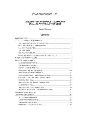
What areas are considered mountainous? (AIM 5-6-5)What are the different en route altitudes? (91.177) (IPH 2-35)MEA (minimum en route altitude) – lowest altitude that provides both obstacle clearanceand NAVAID reception.Adequate communication is not always guaranteed at the MEA. In some instances,NAVAID reception at the MEA isn’t guaranteed either! When this happens, the wordsMEA GAP are printed on the airway. See V187 that extends NW from the RSK VORTACMOCA (minimum obstacle clearance altitude) – lowest altitude that meets obstacleclearance requirements but only guarantees NAVAID reception within 22nm. TheMOCA is designated with an * symbol
MRA (minimum reception altitude) – lowest altitude at which a fix can be identified. Forexample, if there is a fix marked by two intersecting VOR radials, the aircraft must be ator above the MRA if one is published in order to receive both signals. It is marked on thelow en route chart with a flag and an R inside of it at the fix.MAA (maximum authorized altitude) – highest altitude where adequate NAVAIDreception is guaranteedMTA (minimum turning altitude) – lowest altitude at which an aircraft can safely turnfrom one leg of an airway to the next. Different factors such as aircraft speed and theangle at which the airways join create a need for obstacle clearance in a greater area. TheMTA provides obstacle clearance for both, fly by fixes (where the turn is begun prior toreaching the fix) and also for fly over fixes (where the turn can only begin after crossingthe fix). The aircraft must be at or above the MTA before beginning the turn in eithercase. See the JAC VOR for an example of an MTA.MCA (minimum crossing altitude) – lowest altitude at which a fix can be safely crossed.It is marked on the low en route chart with a flag and an x inside of it at the fix.
Chart Symbols
What are the required reporting points while en route? MARVELOUS VFR 500(AIM 5-3-3) (IPH 2-45)Missed approachAirspeed change of 5% or 10 knots (whichever is greater)Reaching clearance limit or holding fixVacating an altitudeETA change of more than 2 minutesLeaving assigned altitudeOuter Marker inbound (non-radar environment only)Unforecasted weather conditionsSafety of flight (anything that affects it)VFR on top altitude changeFinal approach fix inbound (non-radar environment only)Radio failure500fpm – unable to maintainWhat information should be included in each report? (AIM 5-3-3) (IPH 2-45)1. Aircraft identification2. Position3. Time
4. Altitude or flight level5. ETA and name of next reporting point6. The name only of the next succeeding reporting point7. Pertinent remarksWhat are the appropriate procedures for in the case of a communications failureunder IFR? AVEF MEA (91.185) (IPH 2-47)Squawk 7600. In the event that you are in VMC, stay VMC and land as soon as practicalChoose your route in this order1. Assigned route2. Vectors (if you are receiving vectors to a fix and you lose communication, fly directto that fix)3. Expected4. FiledChoose whichever altitude is highest1. MEA2. Expected3. Assigned
What are the maximum holding speeds? (AIM 5-3-3) (IPH 2-51)In what direction should turns be made in a standard holding pattern?To the rightWhat are the IFR fuel requirements? (91.167)Enough fuel to fly to the destination with a 45 minute reserve. When an alternate isneeded, there must be enough fuel to fly to the destination and the alternate with a 45minute reserve.
When is an alternate required?Whenever the weather at the destination airport has a ceiling of less than 2000’ orvisibility less than 3sm during a period beginning 1 hour before the ETA and ending 1hour after.What are the standard weather requirements to file an airport as alternate?Precision approach – 2 miles visibility and 600’ ceilingNonprecision approach – 2 miles visibility and 800’ ceilingCan you choose an airport without an IAP as an alternate?If there is no published procedure, the weather must allow a descent from the MEA to alanding under VFR.How would you know if an airport has other than standard alternate minimums?When you see this symbol, go to the alternate minimums section of the TPPsto see what the weather requirements are to file this airport as an alternate.
What airports cannot be filed as alternates? (IPH 1-12)NA means that alternate minimums are not authorized due to either an unmonitoredfacility, absence of weather reporting, or inadequate navigation coverage.Can an airport that only has a GPS be filed as an alternate? (AIM 1-1-18 e. 2) (IFH9-26) (IPH 1-12 and 4-23)Only if the aircraft is equipped with WAAS capable GPS certified under TSO-C145 orTSO-146What are TEC routes? (AIM 4-1-19) (IPH 2-10)Tower En route Control is a service that allows pilots to travel between airports in selectmetropolitan areas without leaving approach control airspace. It is designed to expediteair traffic and reduces ATC and pilot communications. You can find these routes in theTower En route Control section of the Chart Supplement.
What are preferred IFR routes? (IPH 2-7)Established between busier airports to increase system efficiency and capacity and helppilots plan their route of flight. See the preferred IFR routes section of the ChartSupplements for more details.What is RNP? (AIM 1-2-2 and 5-4-5) (IFH 9-44) (IPH 1-30, 2-34, 4-26)RNP describes the course route width of an RNAV route. The aircraft’s total system errormust remain bounded to the appropriate level for 95% of the total flight time.
When does the sensitivity change from en route to terminal and terminal toap
Define “appropriately rated safety pilot.” (91.109) The safety pilot must possess at least a private pilot certificate with the category and class ratings appropriate to the aircraft being flown and he/she must have