Transcription
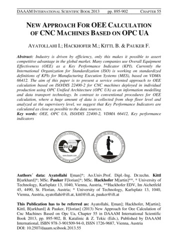
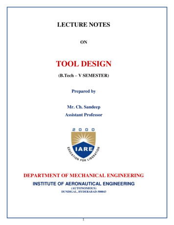
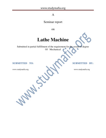
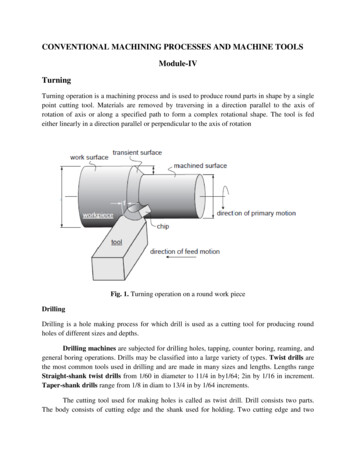
CONVENTIONAL MACHINING PROCESSES AND MACHINE TOOLSModule-IVTurningTurning operation is a machining process and is used to produce round parts in shape by a singlepoint cutting tool. Materials are removed by traversing in a direction parallel to the axis ofrotation of axis or along a specified path to form a complex rotational shape. The tool is fedeither linearly in a direction parallel or perpendicular to the axis of rotationFig. 1. Turning operation on a round work pieceDrillingDrilling is a hole making process for which drill is used as a cutting tool for producing roundholes of different sizes and depths.Drilling machines are subjected for drilling holes, tapping, counter boring, reaming, andgeneral boring operations. Drills may be classified into a large variety of types. Twist drills arethe most common tools used in drilling and are made in many sizes and lengths. Lengths rangeStraight-shank twist drills from 1/60 in diameter to 11/4 in by1/64; 2in by 1/16 in increment.Taper-shank drills range from 1/8 in diam to 13/4 in by 1/64 increments.The cutting tool used for making holes is called as twist drill. Drill consists two parts.The body consists of cutting edge and the shank used for holding. Two cutting edge and two
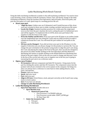
opposite spiral are cut into its surface The flute provides clearance to the chips produced at thecutting edge.The surface on the drill that extends behind the cutting tip to the following flute istermed as flank.The face is the portion of the flute surfaceadjacent to the cutting tip on which thechip moves.The land or the margin is the cylindrically ground body surface on the leading edgeor flank face.The axial rake angle is the angle between face and the line parallel to the drill axis.Tolerances have been set on the various features of all drills so that the products of differentmanufacturers will be interchangeable in the user’s plants. Twist drills are decreased in diameterfrom point to shank (back taper) to prevent binding. If the web is increased gradually inthickness from point to shank to increase the strength, it is customary to reduce the helix angle asit approaches the shank. The shape of the groove is important, the one that gives a straightcutting edge and allows a full curl to the chip being the best. The helix angles of the flutes varyfrom 100to 450. The standard point angle is 1180. There are a number of drill grinders on themarket designed to give the proper angles. The point may be ground either in the standard or thecrankshaft geometry.Fig. 2. Straight shank twist drill
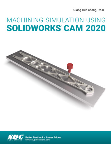
Fig.3.Various types of drills and drilling and reaming operationsDrilling time estimationTypical process parameters used for drilling operation are as followsWork materialCast IronCast steelAISI 1020AISI 1040Manganese SteelNickel steelStainless steelSpring steelTool steelTool steelTool steelMalleable ironAluminiumAluminium alloysCopperBrassBronzeHardness 200215110-13095170-19080-85190-200180-200HSSSpeed m/min25-3512-1535255181562318152627518217054Feed 0.20-0.50
Drilling time estimationThe cutting speed in drilling is the surface speed of twist drill.V DN1000V cutting speed (surface), m/minD diameter of twist drill, mmN rotational speed of drill, rev/minThe drill will have to approach the start of hole from a distance and traverse beyond the actualhole by a distance termed as the total approach allowance A. The initial approach is a small valuefor positioning the drill above the hole. The distance AI can generally be taken as 2 to 3mm.Thetraverse distance beyond the hole is termed as the breakthrough distance.A Breakthrough distanceD2 tan For common case, α 590A D3.3286Total length of tool travel L l A 2mmWherel length of the holeTime for drilling the hole LminutesfNF feed rate,mm/revMillingThrough milling process flat and complex shapes are formed by using multipoint cutting tool.The axis of rotation of cutting tool is perpendicular to the direction of feed. During eachrevolution of cutting operation the teeth of milling cutter enter and exit the work piece. Thereforeon every rotation the teeth are subjected to impact force and thermal shock.The tool material andgeometry must be designed to resist the conditions.
TYPES OF MILLING MACHINETo satisfy the variety of requirement, milling machine comes in a number of ways, sizes andvarieties.a) Knee and column typeb) Horizontalc) Verticald) Universale) Turret typeThese are the general purpose milling machine, which have a high degree of flexibility andemployed for all types of works, including batch manufacturing.f) Production (bed) typeg) Simplexh) DuplexTriplex these machines are generally meant for regular production involving large batch sizes.The flexibility is relatively less in these machines than suitable for productivity enhancement.i) Plano millers- these machines are used only for very large work-piece involving tabletravels in metres.j) Special type Rotary tableDrum typeCopy milling (die sinking machine)Keyway milling machinesSpline milling machineThese machines are of a special facilities to suit specific applications that catered by the otherclasses of milling machines.KNEE AND COLUMN MILLING MACHINEThe knee and column type milling machine is the most commonly used machine in view of itsflexibility and easier setup. The knee houses the feed mechanism and mounts the saddle andtable. The table basically has the t-slots running along the x-axis for the purpose of work holding.The table moves along the x-axis on the saddle while the saddle moves along the y-axis on the
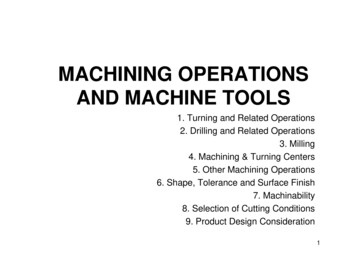
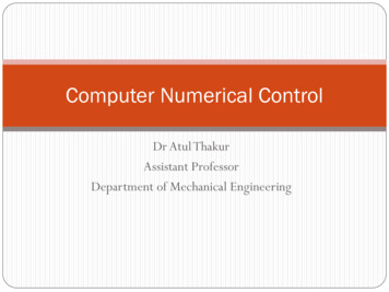
guideways provided on the knee. The feed is provided either manually by hand wheel orconnected for automatic by the lead screw, which in turn is coupled to the main spindle drive.The knee can move up and down in a dovetail provided on the column.Milling machines are generally specified based on the following features. Size of the table, which specifies the actual working area on the table and relates to themaximum size of the work-piece that can be accommodated. Amount of table travel which gives the maximum axis movement that is possible. Horse power of the spindle, which actually specifies the power of the spindle motor used.Smaller machines may come with 1 to 3 hp while the production machines may go from10 to 50 hp.Another type of knee and column milling machine possible is the vertical-axis type. Most of theconstruction is very is very similar to the horizontal-axis type except the spindle type andlocation. The spindle is located in the vertical direction and is suitable for using the shankmounted milling cutter such as end mills. In view of the location of the tool, the setting up of thework-piece and observing the machining operation is more convenient.The universal machine is suitable for milling spur and helical gears, as well as worm gears andcam as it can be swivelled in a horizontal plane about 45 degree to either left or right.BED-TYPE MILLING MACHINEThese are made more rugged and consequently are capable of removing more material withoutany chatter. Here the table is directly mounted on the bed and is provided with only thelongitudinal motion. The spindle will be moving along with the column to provide the cuttingaction.Simplex machines are the ones with only one spindle head while duplex machines have twospindles.Milling operations are of two types Down millingHere the cutter direction is same direction as the motion of the work piece being fed. Up millingHere work piece is moving towards the cutter, opposing the cutter direction ofrotation.Surface finish is better in case of down milling,but the stress load on the teeth isabrupt that may damage the cutter.
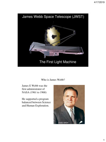
Fig.4. Schematic depiction of down milling (a) and up milling (b) operationsAdvantages1.2.3.4.5.6.Suited to machine-thin and hard to hold partsWork need not be clamped tightlyConsistent parallelism and size may be maintained particularly on the thin partsUsed where break out of the edge of the work piece could not be tolerated.Requires up to 20% less power to cut.Used when cutting off stock or when milling deep, thin slots.Disadvantages1. Cannot be used unless the machine has a backlash eliminator and the table jibs have beentightened2. Cannot be used for machining castings or hot rolled steel, since hard outer scale willdamage the cutter.GrindingGrinding is the most common form of abrasive machining. It is a material cutting process thatengages an abrasive tool whose cutting elements are grains of abrasive material known as grit.These grits are characterized by sharp cutting points, high hot hardness, chemical stability andwear resistance. The grits are held together by a suitable bonding material to give shape of anabrasive tool. Grinding machine is employed to obtain high accuracy along with very high classof surface finish on the work piece. However, advent of new generation of grinding wheels andgrinding machines, characterized by their rigidity, power and speed enables one to go for highefficiency deep grinding (often called as abrasive milling) of not only hardened material but alsoductile materials.
Grain sizeCompared to the normal cutting tool, the abrasive used in grinding wheels are relatively small.The size of an abrasive grain or more generally called grit is identified by a number which isbased on the sieve size used. This would vary from a very coarse size of 6 to 8 to a super finesize of 500 or 600. Sieve number is specified in terms of the number of opening per square inch.The surface finish generated would depend upon grain size used. The fine grain will take a verysmall depth of cut and hence a better surface finish is produced. Fine grains generate less heat aregood for faster material removal. Fine grains are used for making the form grinding wheels.Coarse grains are good for higher material removal rates. These have better friability and as aresult are not good for intermittent where they are likely to chip easily.Bonded Abrasives A composite of the abrasive powder and a matrix Bonding material can be glass, resin, rubber. Can be solid discs (grinding wheel) or bonded to paper/cloth which is then stuck to a backingdisc.The most commonly used bond materials are VitrifiedSilicateSynthetic resinRubberShellacMetalCENTRE-LESS GRINDINGIt is used to grind cylindrical work-piece without actually fixing the work-piece using centres ora chuck, due to which the work rotation is not provided separately.Its process consists of wheel, one large grinding wheel and another smaller regulating wheel. Thework-piece is supported by the rest blade and held against the regulating wheel by the grindingforce which is mounted at an angle to the plane of grinding wheel. The regulating wheel isgenerally a rubber or resinoid bonded wheel with wide face. The axial feed of the work-piece iscontrolled by the angle of tilt of the regulating wheel. Typical work speeds are about 10 to 50m/mm.There are three types of centre-less grinding operations possible. They are:a) Through feed centre-less grinding.b) In feed centre-less, the grinding is done by plunge feeding so that any form surface canbe produced. This is useful if the work-piece has an obstruction which will not allow it to
be traversed past the grinding wheel. The obstruction could be a shoulder, head, roundform, etc.c) End feed centre-less grinding, where tapered work-piece can be machined.Fig.5. Cutting action of abrasive grainConventional grinding machines can be broadly classified as:(a) Surface grinding machine(b) Cylindrical grinding machine(c) Internal grinding machine(d) Tool and cutter grinding machineAdvantagesA grinding wheel requires two types of specification dimensional accuracy good surface finish good form and locational accuracy applicable to both hardened and unhardened materialApplications surface finishing slitting and parting descaling, deburring stock removal (abrasive milling) finishing of flat as well as cylindrical surface
grinding of tools and cutters and re sharpening of the same.Conventionally grinding is characterized as low material removal process capable of providingboth high accuracy and high finish. However, advent of advanced grinding machines andgrinding wheels has elevated the status of grinding to abrasive machining where high accuracyand surface finishas well as high material removal rate can be achieved even on an unhardenedmaterialBroachingBroaching is a machining process for removal of a layer of material of desired width and depthusually in one stroke by a slender rod or bar type cutter having a series of cutting edges withgradually increased protrusion as indicated in Figure. The difference in broaching and shaping, isthat broaching enables remove the whole material in one stroke only by the gradually rising teethof the cutter called broach where as shaping requires a number of strokes to remove the materialin thin layers step by step by gradually infeeding the single point tool. Machining by broachingis preferably used for making straight through holes of various forms and sizes of section,internal and external through straight or helical slots or grooves, external surfaces of differentshapes, teeth of external and internal splines and small spur gears etc.Fig.6.Principle of BroachingFigure shows how a through hole is enlarged and finished by broaching.
Chip breakerFig.7.Vertical push typeFig.8.Horizontal pull typeFinishing hole by broachingConstruction of broaching toolsConstruction of any cutting tool is characterized mainly by Configuration Material Cutting edge geometry
Both pull and push type broaches are made in the form of slender rods or bars of varyingsection having along its length one or more rows of cutting teeth with increasing height (andwidth occasionally). Push type broaches are subjected to compressive load and hence aremade shorter in length to avoid buckling.Fig. 9.Pull type broach toolThe essential elements of the broach are : Pull end for engaging the broach in the machine Neck of shorter diameter and length, where the broach is allowed to fail, if at all,under overloading Front pilot for initial locating the broach in the hole Roughing and finishing teeth for metal removal Finishing and burnishing teeth Rear pilot and follower rest or retrieverAdvantages of broaching:1. It is the fastest way of finishing an operation with a single stroke.2. Very little skill is required from the operator.3. It is simple since only a single reciprocating motion is required for cutting.4. Final cost of the machining is one of the lowest for mass production.5. Any type of surface, internal or external can be generated with broaching.6. Good surface finish and fine dimensional tolerance can be achieved.
Limitations of broaching:1. Custom made broaches are very expensive and hence generally used for very largevolume production.2. The lead time for manufacturing is more for custom designed broaches.3. A broach can be designed and used for a specific application.4. As it is a very heavy metal removal operation, it requires that work-piece is rigid andcapable of withstanding the large forces.It can only be carried out on the work-piece whose geometry is such that there is no inference forbroach movement for the cuttingSuper finishing processesThe surface finish has an important role in influencing functional characteristics like wearresistance, fatigue strength, corrosion resistance and power loss due to frictional properties. Asnormal machining methods like turning, milling or even classical grinding cannot meet thisrequirements,therefore in order to improve the performance and increase the prolong service lifeof modern machinery, the components required to be manufactured with high dimensionalaccuracy and high surface finish.ProcessDiagramsurfaceofresulting Height of micro irregularity( m)Precision Turning1.25-12.50Grinding0.90-5.00Honing0.13-1.25
Lapping0.08-0.25Superfinishing0.01-0.25Lapping, honing, polishing, burnishing are some of the super finishing processes that areemployed to achieve above properties.LappingLapping is the method of obtaining a fine finish. Lapping is basically an abrasive process inwhich loose abrasives function as cutting points finding momentary support from the laps.Following Figure represents the lapping process. Material removal in lapping usually rangesfrom .003 to .03 mm but many reach 0.08 to 0.1mm in certain cases.Characteristics of lapping process: Use of loose abrasive between lap and the work piece.Usually lap and work piece are not positively driven but are guided in contact with eachother.In order to avoid the repetitive path of the abrasive grains of the lap on the work piece,relative motion between the lap and the work should change continuouslyLAPAbrasive particleVehicleWork PieceFig.10.Lapping processCast iron is the mostly used lap material. However, soft steel, copper, brass, hardwood as well ashardened steel and glass are also used.Abrasives of lapping
Al O and SiC, grain size 5 100μm2323 Cr O , grain size 1 2 μm B C , grain size 5-60 μm43 Diamond, grain size 0.5 5 VVehicle materials for lapping Machine oil Rape oil greaseTechnical parameters affecting lapping processes unit pressure grain size of abrasive concentration of abrasive in the vehicle lapping speedHoningHoning is a finishing process, in which a tool called hone carries out a combined rotary andreciprocating motion while the work piece does not perform any working motion. The honingstones are held against the work piece with controlled light pressure. Honing is generally done oninternal cylindrical surface, such as automobile cylindrical walls.Following assumptions are considered during honing processes. Honing stones should not leave the work surface. Stroke length must cover the entire work length.BurnishingBurnishing process carries a pressing hardened steel rolls or balls into the surface of the workpiece that imparting a feed motion to the work piece.
Fig.11.Ball burnishingDuring the process, compressive stress is induced on the work pieceElectro polishingElectro polishing is the reverse of electroplating. In this process, the work piece acts as anodeand the material is removed from the work piece by electrochemical dissolution. The process isparticularly suitable for polishing irregular surface since there is no mechanical contact betweenwork piece and polishing medium. This process is also suitable for deburring operation.CENTER LATHEIntroductionLathe is the oldest tool invented, starting with the Egyptian tree lathe. In Egyptian tree lathe, oneend of the rope wound round the work-piece is attached to a flexible branch of a tree, while theother end is pulled by the operator, thus giving rotary motion to the work-piece. It is one of themost fundamental and versatile device, used practically in all the manufacturing shops.The principal form of surface produced in the lathe is the cylindrical surface. It is achieved byrotating the work-piece, while single-point cutting tool removes the material by traversing in adirection parallel to the axis of rotation.A large number of variants of lathes are used in manufacturing shops. The variations are1. Centre lathe(engine lathe)
Bench lathe2. Tool room lathe3. Special purpose lathes Copying lathe Gap bed lathe Hollow spindle lathe4. Capstan and turret lathe5. Automatic latheThe centre lathe (commonly used), which derives its name from the way a work-piece is clampedby centre in a lathe, though this is not the only way in which the job is mounted.The tool room lathe is generally meant for tool making where accuracy is of higher priority.Thus, the machine would have a higher range of speeds and feeds along with greater rigiditywith a larger range of accessories and attachments.The special purpose lathes are developed from the centre lathe to crater to special forms ofapplication, which cannot be handled by the conventional centre lathe.Capstan and turret lathes are used for very special application as they have high rate ofproduction.CONTRUCTIONAL FEATURES OF A CENTRE LATHEThe major elements present in the lathe are:1. The headstock - fixed towards the left end of the bed and houses the power source, powertransmission, gear box, and spindle)2. The main gear box – provides the necessary spindle speed as per the range of materials tobe turned. The feed gear box provides the various feed rates and thread cutting ranges.3. The tailstock – fixed towards the right end of the bed. It has a tailstock spindle to locatethe long components by the use of centres. It moves on inner guideways to accommodatethe different lengths of work-piece. Its also serves the purpose of holding tools, formaking and finishing holes in the components that are located in the line with the axis ofrotation.
4. The carriage – it provides the necessary longitudinal motion to the cutting tool togenerate the necessary surface. This also houses the cross slide (to provide cross feed tocutting tool) and compound slide (to provide auxiliary motion to cutting tool).5. Lead screw – it communicates the motion from the spindle motor to the carriage. Itengages with the carriage through a half nut. It can also be used for feeding the cuttingtool in a direction parallel to the axis of rotation, but it is sparingly used for threadcutting, such that it maintains its accuracy.6. Feed rod – it is used for routine feeding of cutting tools.LATHE SPECIFICATIONThere are a number of factors that should be specified to fully describes a lathe machine. Theyare: Distance between centres - specifies the maximum length of the job that can be turned. Swing over the bed- specifies the maximum diameter of the job that can be turned. Swing over the cross-slide – specifies the maximum diameter of the job that can be turnwith the job across the cross-slide. Horse Power of motor. Cutting speed range Feed range. Screw cutting capacity Spindle nose diameter and hole sizeAIDS FOR SUPPORT AND LOCATIONThe work holding devices normally used should have the following provisions: Suitable location Effective clamping SupportCHUCK is the most common form of work holding device used in lathe. It is available withvarying number of jaws. Three jaw chuck or self-centring chuck is the most common one of all.Its main advantage is the quick way in which the typical round job is centred. All the three jawswould be meshing with the flat scroll plate. Rotating the scroll plate through a bevel pinion
would move all the three jaws radially, inward or outward, the same amount. Thus, the jawswould be able to centre any job whose external locating surface is cylindrical or symmetrical. Ithas limitation in terms of gripping force and accuracy.The independent jaw chuck has four jaws, which can be moved in their slots independent of eachother. Hence better accuracy can be maintained. But fixturing of a component is more timeconsuming. Its jaws can be reversed to clamp larger diameter work-piece.The three-jaw and four-jaw chucks are suitable for short components. However, in case of longcomponents support at one end is not sufficient, as is done in case of chucks, would make it todeflect under the influence of the cutting force. In such cases, the long work-piece is held inbetween the centres. The work-piece is provided with a centre hole. Through this centre hole, thecentres mounted in the spindle and the tailstock would rigidly locate the axis of work-piece. Totransmit motion to the work-piece from the spindle a carrier plate and a dog is used. The centrelocated in the spindle is termed as live centre, while that in the tailstock is termed as dead centre.The shank of the centre is generally finished with a more taper which fits into the tapered hole ofthe spindle or tailstock.There is a relative motion between the work-piece and the dead centre (live centre only rotateswith the work-piece). As a result a large amount of heat is generated. For this, a revolving centreis used, that is mounted in roller bearing and thus rotates freely.Some precautions to be observed during the use of centres are: The centre hole in the work must be clean and smooth and have an angle of 60 degreebearing surface, large enough to be consistent with the diameter of the work. For heavierwork, this may be made 75 degree or 90 degrees. The bearing must take place on the counter sunk surface, and not at the bottom of thedrilled hole.For odd shaped components, a faceplate is more widely used, where the locating and clampingsurface need not be circular. There are radial slots on the plate, for the purpose of locating thecomponent and clamping by means of any standard clamps. There is the possibility of massunbalance. A balancing mass would therefore be provided. Sometimes angle plates along withthe faceplate may have to be used for typical components, where the locating surface isperpendicular to the plane of the faceplate.Collet provides good clamping accuracy with very little time required for clamping andunclamping. It has the holding part, which is slit along the length at a number of points along thecircumference. When the uniform pressure is applied along the circumference of the sleeve,these segments would elastically deflect and clamp the component located inside. Tis clampingmethod is very accurate.
OPERATION PERFORMED IN A CENTRE LATHEBased on the various settings that are possible, following are the types of operations performedof centre lathe: TURNING- Here cylindrical surfaces are generated. In this case, the work held in thespindle is rotated while the tool is fed past the work-piece in a direction parallel to theaxis of rotation. FACING- It is an operation generating flat surfaces. The feed given here is perpendicularto the axis of revolution and the radius of work-piece at the contact point variescontinuously as the tool approaches the centre and hence varies the resulting cuttingspeed. KNURLING OPERATION- It is a metal operating operation. In this, a knurling toolhaving the requisite serration is forced on to the work-piece thus deforming the top layer. PARTING OPERATION- parting and grooving are similar operations. In this a flatnosed tool would plunge cut the work-piece with a feeding a direction perpendicular tothe axis of revolution. It is used for cutting off the part from the parent material or to get arectangular groove. DRILLING- It is the operation of making cylindrical holes into the solid material. Atwist drill is held in the quill of the tailstock, and is fed into the rotating work-piece byfeeding the tailstock quill. This operation is limited to holes through the axis of rotationof the work-piece. BORING- It is the operation for enlarging the holes already made by a single pointboring tool termed as boring bar.5- SPECIAL- PURPOSE LATHESThe main limitations of centre lathe are: The setting time for the job in terms of holding the job is large. Only one tool can be used in the normal course. Sometimes the conventional tool postcan be replaced by a square tool post with four tools. The idle times involved in the setting and movement of tools between the cut is large. Precise movement of the tool to destined places is difficult to achieve without propercare exercised by the operator.The centre lathe is modified to improve the production rate. The various modified lathes are:
Turret and capstan lathe, Semi-automatics , and Automatics.The improvements are achieved basically in the following areas: Wok holding methods Multiple tool availability Automatic feeding of the tools Automatic stopping of tools at precise locations Automatic control of the proper sequence of operations.CAPSTAN AND TURRET LATHEThe main characteristic features of capstan and turret lathes are: These are semiautomatic. Possess an axially movable indexable turret (mostly hexagonal) in place of tailstock. Holds large number of cutting tools; up to four in indexable tool post on the front slide,one in the rear slide and up to six in the turret (if hexagonal). Thus, the total carryingcapacity is a maximum of 14 tools when only one tool is mounted in each of thelocations. Are more productive for quick engagement and overlapped functioning of the tools inaddition to faster mounting and feeding of the job and rapid speed change. Enable repetitive production of same job requiring less involvement, effort and attentionof the operator for pre-setting of work-speed and feed rate and length of travel of thecutting tools. Are relatively costlier than centre lathe. Are suitable and economically viable for batch production or small lot production.DIFFERENCE BETWEEN CAPSTAN AND TURRET LATHE:
CAPSTAN LATHETURRET LATHE1. Capstan lathe is limited to themanufacture of work from bar fedduring the empty spindle held in acollect and the standard machinecontain a condition for fixing a jawchuck to the spindle nose thus thatbars, castings and forging might beheldSpindle nose of this machine is threadedoutwardly for screwing faceplate force plate,lathe chuck or any other work holding deviceproper to the job stock. Inside hole is taperedto get the lathe centre and proper collect forbar holding.2. Tailstock does not give for centresupport of bar stock and rising ofshank tools. Tail stock hold up is notrequired as short piece bar stock isuse for work production.Tailstock is moreover give for centre hold upof the bar stock and rising of shank tools.Tailstock be able to bolted at the great righthand of the bed or among carriage with turretslide.3. Capstan head move about on thecapstan slide in the move familiar bythe stop while the whole unit left overbolted on the right handoff the bedways.Turret head rise on the ramslide movelongitudinally in the move familiar by thestop screws. Whole nit be
CONVENTIONAL MACHINING PROCESSES AND MACHINE TOOLS Module-IV Turning Turning operation is a machining process and is used to produce round parts in shape by a single point cutting tool. Materials are removed by traversing in a direction parallel to the axis of rotation of axis or along