Transcription
orMasonryAnalysisandDesignPreface: The importance of good structural software can’t be underestimated as a tool for today’sstructural engineer. During the last few years, the software options available to structuralengineers for masonry design have grown and the use of masonry structurally has become moreprevalent and sophisticated.To support the engineering community in the use of structuralmasonry, the FORSE Consulting, LLC has funded this manual.Date: November 25, 2014Copyright 2014 of FORSE Consulting, LLC1st edition1
RISA 3D for Masonry Design (from FORSE Consulting, LLC and IMI)RISA 3D is one of the few commercially available, finite element analysis based, structural analysisand design programs that provide tools for effective modeling and design of masonry structures.RISA 3D can be used to create an entire building that includes masonry, or simply model and designan individual masonry wall panel. It provides code checks for masonry load bearing walls, masonryshear walls, masonry wall lintels, and masonry columns at the end of wall panels. The code checkoptions are as follows: ACI 530-11 SD ACI 530-11 ASD ACI 530-08 SD ACI 530-08 ASD ACI 530-05 SD ACI 530-05 ASD ACI 530-02 SD ACI 530-02 ASD ACI 530-99 ASD UBC 1997 SD UBC 1997 ASDIt also can design hybrid masonry/frame structures and handles both reinforced and unreinforcedmasonry using concrete masonry units or clay brick units in a variety of compressive strengths andunit configurations. RISA 3D is one of the software packages recommended by the InternationalMasonry Institute for masonry wall design.About RISA 3D (from RISA Technologies, LLC)[RISA 3D has] the most current steel, concrete, cold-formed steel, masonry, aluminum and timberdesign codes, RISA-3D gives you the tools to tackle multi-material projects with confidence.About International Masonry Institute (IMI)The International Masonry Institute offers quality training for craftworkers, professional educationfor masonry contractors and free technical assistance to the design and construction communities.IMI is a strategic alliance between the International Union of Bricklayers and Allied Craftworkers(BAC) and their signatory contractors to promote quality masonry construction.Team IMI consists of architects, engineers, construction managers, skilled craftworkers andinstructors, offering what no other group can: expertise in training, craftsmanship, design, installationand marketing. That means buildings built by union craftworkers and contractors get built the rightway.AuthorsSamuel M Rubenzer, PE, SE FORSE Consulting, LLCBrady Golinski, PE FORSE Consulting, LLC right 2014 of FORSE Consulting, LLC2
DisclaimerThis file is a PDF version of the embedded masonry tutorial found in the help section of RISA3D and is subject to all licensing agreements, copyrights and other protections associated withthe software. It is reproduced here as a convenience to the user. The software, including thistutorial, was developed for use as a design aid for qualified engineers. Considerable care wasused in its preparation, but it should not be used in the absence of sound engineering judgmentand knowledge. The engineer of record is always responsible for data used in design and resultsobtained whether from a calculator or from computer software.IMI and FORSE Consulting, LLC disclaims all warranties, expressed or implied, including butnot limited to implied fitness for a particular purpose, with respect to this manual. All designsresulting from the processes defined in this manual should be verified to your satisfaction. Thecontents of these written materials may include technical inaccuracies or typographical errorsand may be revised without notice.This document is intended for the use of industry professionals who are competent to evaluatethe significance and limitations of the information provided herein. This publication should notbe used as the sole guide for masonry design and construction.Copyright 2014 of FORSE Consulting, LLC3
sinRISA- ‐3Dv11.51.Open RISA-3D.52.Learn about the application interface.53.Begin by defining CMU properties.54.Define masonry geometry.75.Define loads.106.Model design and analysis.117.Save model and end.11Section2:MoreinformationaboutmasonryinRISA- cturemodel.12Copyright 2014 of FORSE Consulting, LLC4
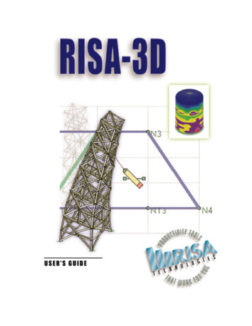
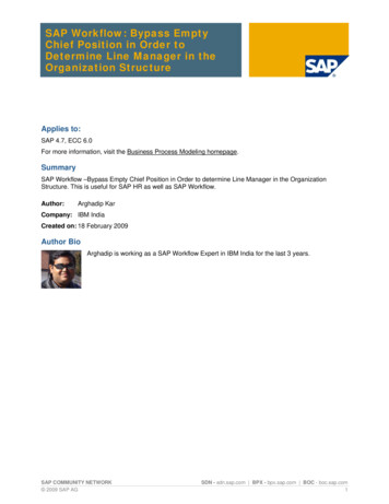
Section 1: Work flow for masonry buildings in RISA-3D v111. Open RISA-3D2. Learn about the application interfacea. Toolbars for navigation, model viewing, and editing datab. Spreadsheetsi. Nodes, members, boundary conditions, materials, wall panels/plates, loadsc. Graphic toolsi. These do everything that the spreadsheets do, but directly in the modelrather than tabular formatd. Wall panel editori. Editing tool specifically for wall panelsScreen shot 1—application interfaceModeling Tip: right click on the view screen to access these tools3. Begin by defining CMU propertiese. Use Materials spreadsheet Masonry tab to define structural propertiesi. Modulus of elasticityCopyright 2014 of FORSE Consulting, LLC5
f.g.h.i.ii. Masonry strength (f’m)iii. Reinforcing yield strengthiv. Masonry self weightUse Wall Design Rules spreadsheet Masonry Wall tab to define block size andgrout spacingi. Nominal block widthii. Grouting—fully, partially (at reinforced cells), ungroutediii. Reinforced versus unreinforcedWall Design Rules spreadsheet Masonry In tab for in-plane design parameters—boundary steel at wall endsi. Vertical bar sizeii. Bars per celliii. Minimum and maximum boundary zone widthiv. Horizontal bar sizev. 1.5x shear multiplier for high seismic zones per IBC 2006 2106.5.1vi. Transfer load—will transfer in-plane loads from regions above and belowopenings to adjacent regionsWall Design Rules spreadsheet Masonry Out tab for out-of-plane designparametersi. Vertical bar sizeii. Minimum and maximum vertical bar spacingiii. Bar placement (center of cell, each face, or staggered)iv. Mortar typev. Cement typevi. Transfer load—will transfer out-of-plane loads from regions above andbelow openings to adjacent regionsWall Design Rules spreadsheet Masonry Lintel tab to define lintel designparametersi. Lintel depthii. Lintel bearing lengthiii. Bar sizeiv. Minimum and maximum number of barsv. Number of reinforcing layersvi. Layer spacing, if more than onevii. Distance from bottom layer to bottom of lintelviii. Stirrup sizeCopyright 2014 of FORSE Consulting, LLC6
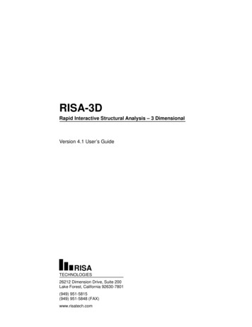
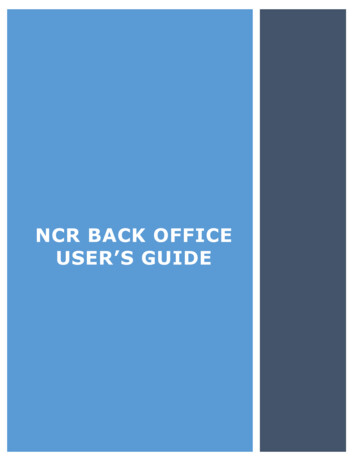
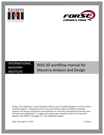
Screen shot 2—Masonry Properties and Masonry Wall Panel spreadsheetsModeling Tip: Multiple design rules can be input on all of the tabs listed above to account fordifferent designs within the same project4. Define masonry geometryj. Start with one masonry wall elevationi. Add nodes at wall corners in Joint Coordinates spreadsheetii. Draw wall using Draw New Wall Panels tool in Graphic Editing Toolbar.iii. It is possible to draw a new wall without adding joints first if using theDrawing GridCopyright 2014 of FORSE Consulting, LLC7
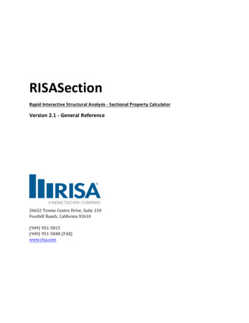
Screen shot 3—select nodes in this order when drawing wall panelsModeling Tip: Nodes/grid corners must form a rectangular shape for wall to be drawnk. Stack walls at multistory conditionsl. Define a new wall panel where out of plane load changesi. Can also change material and/or design rulesModeling Tip: If adjacent wall panels (horizontally or vertically) share joints at corners, theywill behave as a continuous wallm. Control jointsi. Program does not have a way to model control joints directly, but they canbe approximated by creating a gap and a gap element1. Place wall panel edges a distance apart that corresponds to thecontrol joint width2. Add a fully rigid, compression-only gap member between wallpanelsCopyright 2014 of FORSE Consulting, LLC8
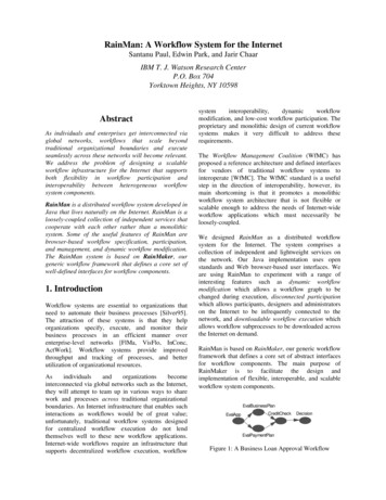
3. Add a negative thermal load to the gap member to achievelongitudinal shrinkage equal to the gap width4. This ensures the panels will act independently until they deflectclose enough to touch each othern. Wall panel editori. Double click on any wall panel to enter the wall panel editorii. Add boundary conditions (this is the only way to add support along anentire panel edge)iii. Define openings in the wall panel1. Must set up a grid for this; nodes are not active in the wall paneleditoriv. Define lintels above openings1. Only one design rule per wall panel2. To have different lintel designs in the same panel, use customdesignv. Define wall regions1. Can be defined automatically by RISA or manually2. Program will automatically assign separate regions above andbelow a diaphragm3. Wall regions can be designed per the design rule of the wall panelor with custom parametersCopyright 2014 of FORSE Consulting, LLC9
Screen shot 4—Wall Panel editor window5. Define loadsa. Set up different cases in the Basic Load Cases spreadsheetb. In-plane loadsi.Apply shear loads as a joint (point) load at a node—apply in Joint Loadsspreadsheet or with Joint Loads graphic toolii.Apply vertical uniform loads from diaphragms with Distributed Loadsgraphic tool—not possible to do in Distributed Loads spreadsheetiii.Gravity load can be applied in the Basic Load Cases spreadsheetc. Out-of-plane loadsi.Apply lateral loads to the entire wall panel with the Surface Loadsspreadsheet or graphic toolii.Surface load can be applied to a portion of the panel height, but must beapplied to full panel widthCopyright 2014 of FORSE Consulting, LLC10
iii.To change lateral pressure, for example near a building corner, start anew wall panelModeling Tip: All load spreadsheets are accessed through the Basic Load Cases spreadsheetd. Set up load combinations with load factors in the Load Combinations spreadsheet6. Model design and analysise. Global Parameters menui.Use Codes tab to set governing code—ACI 530-08 or -11, ASD orLRFDii.Use Solution tab to set the mesh size for finite element analysisf. Analyze the model by clicking Solve on the menu bar or the Equal sign buttoni.Choose which load combination to analyzeii.Analyze Envelope forces of selected load combinationsiii.Analyze multiple load combinations simultaneously with Batch Solutiong. Check Wall Panel Design spreadsheeti.Results are shown on Masonry In, Masonry Out, and Masonry Linteltabsh. Check Detail button on left side of screen (not available for an Envelope Solution)i.Shows details for the wall panel by region, in-plane and out-of-planesectionsii.Shows input and outputiii.Code checks, axial, shear and moment diagramsiv.Wall cross sections showing vertical reinforcing for in-plane and out-ofplane loads7. Save model and endCopyright 2014 of FORSE Consulting, LLC11
Screen shot 5—analysis optionsSection 2: More information about masonry in RISA-3D v111. Masonry parapetsa. RISA does not have a dedicated method to model parapetsb. Parapets can be a separate wall panel continuous with the top of the panel below,or just a continuation of the panel belowc. If a diaphragm is modeled at the roof level, RISA will automatically makeseparate wall regions above and below the diaphragm if the parapet is part of thesame panel as the wall belowd. Add parapet wall pressure as a Surface Load—it’s not necessary to have aseparate wall panel for this2. Non-load bearing wallsa. Non-load bearing walls can be modeled by making sure that floor/roof framingdoes not connect to the top of the wall3. Load bearing wallsa. Members supported on walls will transfer loads directly to the wallsb. Rigid end offsets can be used to account for eccentricity of the memberconnection from the wall centerline4. Masonry wall stiffnessa. Wall stiffness can be updated automatically—Global Parameters menu Solutiontab—under Wall Optimization, select Yesb. Equivalent moment of inertia is calculated from the maximum moment in theregion and used to update the stiffness of the wall during designSection 3: Work flow for importing a Revit Structure modelCopyright 2014 of FORSE Consulting, LLC12
1. RISA-3D v11 can import models from Revit Structurea. Requires separate program—RISA-Revit Link; download from RISAb. Number of round trip transfers between RISA-3D and Revit is unlimitedc. Link maintains geometry and design parametersd. Link creates a separate Exchange file when model is exported from eitherprograme. In the other program, open the Exchange file to import the modelf. Model and exchange file are backed up during each transfer2. Most common method is to begin the model in Revit and transfer to RISA-3Da. The architect usually produces a Revit model first, which can be used as atemplate to start the structural modelb. Revit is a physical model; RISA is an analytical modelc. It is easier to first model complex arrangements or connections in Revit (whichneeds to accurately portray this items) then transfer to a simpler arrangement inRISAd. For example, in Revit, a fixed connection needs to accurately model how a beamconnects to a column for construction documents—in RISA, modeling a fixedconnection provides enough information for accurate analysis3. Items and information that are transferreda. Materials for walls in Revit become General materials, not Masonry, in RISA-3Db. Boundary conditions applied to elements in Revit are applied to the appropriatejoints when transferred to a RISA-3D model—translations, rotations, and springstiffnesses are also transferredc. Walls modeled as Structural in Revit are transferred to RISA-3D as Wall Panelsd. Wall Panels and vertical Plate elements in RISA-3D will be imported into Revitas structural wallse. Wall opening sizes and locations are also transferred between modelsCopyright 2014 of FORSE Consulting, LLC13
Nov 25, 2014 · Masonry Institute for masonry wall design. About RISA 3D (from RISA Technologies, LLC) [RISA 3D has] the most current steel, concrete, cold-formed steel, masonry, aluminum and timber design codes, RISA-3D gives you the tools to tackle multi-material projects wit