Transcription
Configuration Guide for CiscoUnified CommunicationsEnvironmentsCA Unified Communications MonitorVersion 3.7
This Documentation, which includes embedded help systems and electronically distributed materials, (hereinafter referred toas the “Documentation”) is for your informational purposes only and is subject to change or withdrawal by CA at any time.This Documentation may not be copied, transferred, reproduced, disclosed, modified or duplicated, in whole or in part, withoutthe prior written consent of CA. This Documentation is confidential and proprietary information of CA and may not be disclosedby you or used for any purpose other than as may be permitted in (i) a separate agreement between you and CA governingyour use of the CA software to which the Documentation relates; or (ii) a separate confidentiality agreement between you andCA.Notwithstanding the foregoing, if you are a licensed user of the software product(s) addressed in the Documentation, you mayprint or otherwise make available a reasonable number of copies of the Documentation for internal use by you and youremployees in connection with that software, provided that all CA copyright notices and legends are affixed to each reproducedcopy.The right to print or otherwise make available copies of the Documentation is limited to the period during which the applicablelicense for such software remains in full force and effect. Should the license terminate for any reason, it is your responsibility tocertify in writing to CA that all copies and partial copies of the Documentation have been returned to CA or destroyed.TO THE EXTENT PERMITTED BY APPLICABLE LAW, CA PROVIDES THIS DOCUMENTATION “AS IS” WITHOUT WARRANTY OF ANYKIND, INCLUDING WITHOUT LIMITATION, ANY IMPLIED WARRANTIES OF MERCHANTABILITY, FITNESS FOR A PARTICULARPURPOSE, OR NONINFRINGEMENT. IN NO EVENT WILL CA BE LIABLE TO YOU OR ANY THIRD PARTY FOR ANY LOSS OR DAMAGE,DIRECT OR INDIRECT, FROM THE USE OF THIS DOCUMENTATION, INCLUDING WITHOUT LIMITATION, LOST PROFITS, LOSTINVESTMENT, BUSINESS INTERRUPTION, GOODWILL, OR LOST DATA, EVEN IF CA IS EXPRESSLY ADVISED IN ADVANCE OF THEPOSSIBILITY OF SUCH LOSS OR DAMAGE.The use of any software product referenced in the Documentation is governed by the applicable license agreement and suchlicense agreement is not modified in any way by the terms of this notice.The manufacturer of this Documentation is CA.Provided with “Restricted Rights.” Use, duplication or disclosure by the United States Government is subject to the restrictionsset forth in FAR Sections 12.212, 52.227-14, and 52.227-19(c)(1) - (2) and DFARS Section 252.227-7014(b)(3), as applicable, ortheir successors.Copyright 2014 CA. All rights reserved. All trademarks, trade names, service marks, and logos referenced herein belong totheir respective companies.
Contact CA TechnologiesContact CA SupportFor your convenience, CA Technologies provides one site where you can access theinformation that you need for your Home Office, Small Business, and Enterprise CATechnologies products. At http://ca.com/support, you can access the followingresources: Online and telephone contact information for technical assistance and customerservices Information about user communities and forums Product and documentation downloads CA Support policies and guidelines Other helpful resources appropriate for your productProviding Feedback About Product DocumentationIf you have comments or questions about CA Technologies product documentation, youcan send a message to techpubs@ca.com.To provide feedback about CA Technologies product documentation, complete ourshort customer survey which is available on the CA Support website athttp://ca.com/docs.
ContentsChapter 1: Introduction7Differences Between the SPAN and CDR Methods . 7Supported Systems and Devices . 10Architecture and Scalability . 12Chapter 2: Configuration Tasks15Connecting the Collector to a SPAN Port . 15Configuring the Management Console as an FTP Recipient . 17Enabling the Call Stats Setting . 18Enable the Collection of Voice Quality Metrics . 19Enabling Web Access and RTCP for IP Phones . 19Appendix A: Troubleshooting21Monitoring Authenticated SIP Traffic. 21Add or Remove SIP Ports for Monitoring . 21Index23Contents 5
Chapter 1: IntroductionCA Unified Communications Monitor (UC Monitor) supports environments that useCisco Unified Communications Manager (CUCM) for call processing. You have twooptions for collecting call data from CUCM: SPAN method: Connect the UC Monitor collector server to a SPAN (Switched PortAnalyzer) port on the switches that carry the signaling traffic to the CUCM. CDR method: Enable CUCM to use FTP to push call detail records (CDRs) and callmanagement records (CMRs) to the UC Monitor management console. No SPAN isrequired.This document helps a Cisco network engineer configure the SPAN method or the CDRmethod. In addition, this document provides instruction for configuration that isindependent of the collection method, such as adding SIP ports.Note: UC Monitor supports environments in which both the SPAN and CDR methods areconfigured. However, such a configuration is not recommended. With both methodsconfigured, you risk duplication of the data in UC Monitor reports.Differences Between the SPAN and CDR MethodsData CollectionSPAN methodThe collector monitors call traffic through a SPAN port on a switch where CUCM callservers are connected. The collector regularly transmits the call data to themanagement console for display in UC Monitor reports.CDR methodCUCM uses FTP to push CDRs (and CMRs) to the management console, where theyare parsed for the data that appears in UC Monitor reports.Configuration TasksSPAN methodPerform the following tasks to configure your environment:–Configure SPAN ports to mirror signaling traffic to the collector.–Enable the Call Stats setting in a voice-quality-enabled SIP profile.–Enable the collection of voice quality metrics.–Enable web access and RTCP on IP phones.Chapter 1: Introduction 7
Differences Between the SPAN and CDR MethodsCDR methodPerform the following tasks to configure your environment:–Configure the management console as an FTP recipient.–Enable the Call Stats setting in a voice-quality-enabled SIP profile.–Enable the collection of voice quality metrics.Metrics and FeaturesMetricSPAN MethodCDR MethodACOMYesNoCall Setup FailuresYesNoCall VolumeYesYesConcealment RatioYesYesConversational MOSNoNoDelay to Dial ToneYesNoERLYesNoJitterYesYesJitter Buffer LossYesYesLatencyYesYesListening MOSYesYesMOSYesYesPacket LossYesYesPacket Loss (Max)YesNoPackets LostYesYesPackets ReceivedYesYesPost-dial DelayYesNoSeverely Concealed SecondsYesYesSignal In/OutYesNoFeatureSPAN MethodCDR MethodAudio Call Quality reportYesYesAutomatic traceroute investigationsYesNoBaseline traceroutesYesNoCall quality incidentsYesYes8 CA Unified Communications Monitor
Differences Between the SPAN and CDR MethodsCall server group incidentsYesNoCall server incidentsYesNoCall setup incidentsYesNoCall Volume reportYesYesCall WatchYesNoCollector incidentsYesNoInterface Utilization reportYesNoTop Interfaces reportYesNoTop Trunk Groups reportYesNoTop Volume Locations/Phones reportsYesYesTrunk Group Utilization reportYesNoPhone or Endpoint InformationSPAN MethodCDR MethodCall ServerYesNoCodecYesYesDevice TypeYesYesFirmware VersionYesNoIP AddressYesYesLast esPhone NumberYesYesPortYesYesFor CUCM 9.0,this metric can beempty orincorrect.Previous Call ServerYesNoPrevious StatusYesNoProtocolYesYesSerial NumberYesNoStatusYesNoStatus TimeYesNoChapter 1: Introduction 9
Supported Systems and DevicesSwitch AddressYesNoSwitch NameYesNoSwitch PortYesNoSupported Systems and DevicesUC Monitor supports the following Cisco unified communications systems and devices.CA Technologies tested UC Monitor with gateways of the indicated types using themajor call setup protocols: SIP, H.323, and MGCP. UC Monitor supports call volumes ofup to ten million calls per month.Cisco Unified Communications ManagerSPAN method: Versions 7.1 through 9.1 are supported. Later versions may work but have notbeen tested. Support for versions 8.0 and later is available only with UC Monitor versions 3.1and later.CDR method: Versions 8.6 through 9.1 are supported. Later versions may work but have notbeen tested. Version 9.0 incorrectly reports the RTP port for calls, and it does not alwaysidentify the media IP address. These issues can cause call correlation problemsand incorrect device discovery. We recommend that you not use version 9.0.Cisco Unified Border Element (CUBE), Enterprise Edition The device on which CUBE is enabled is discovered as a Session BorderController and appears in the management console on the Other Devices page. SNMP must be enabled on the device. End-of-call statistics in SIP BYE messages must be enabled on the device. Call Watch is not supported for CUBE. The SP Edition of CUBE is not supported.Cisco voice gateways, with T1/E1-PRI connectionsIncluding the H.323 and MGCP protocols and SIP trunks to voice gateways.Analog-type gateways Voice gateways that make an FXO connection are monitored for callperformance data. Call Watch is supported for calls through an FXO connection only if the H.323protocol is used.10 CA Unified Communications Monitor
Supported Systems and DevicesCisco VG-224 gateways These devices provide only call setup metrics. Call quality reporting and Call Watch are not supported for these devices.Cisco ATA 186 analog telephone adapters These devices provide only call setup metrics. Call quality reporting and Call Watch are not supported for these devices.Catalyst 6000 WS-X6608-T1/E1 Blade for Voice Call Watch is not supported for this device. This device returns limited call quality metrics for UC Monitor performancereports.Cisco Unified IP phones 6900 series 7920, for call performance metrics only. Call Watch is not supported for thisphone. 792x, 794x, and 796x series 8941, 8945. The switch address, switch name, and switch port number forthese phones may not be available on the Phone Details report. 8941, 8945, 8961, 9951, 9971. Video metrics can be available from thesephones in a medianet environment.Note: Install the latest firmware for these phones.Cisco Unified IP phones, running in advanced SIP mode7906, 7911, 7941, 7961, 7970, 7971Note: Install the latest firmware for these phones.Cisco IP Communicator softphone Version 2 provides few call quality metrics. Versions 7 and later provide packet loss, jitter, and call setup metrics.Cisco Unified Personal Communicator, version 7.0 Call volume data is obtained for calls to and from this client, such as when thecalls were made and the locations of the endpoints. Call setup failures can be reported from this client.Medianet-enabled devicesUC Monitor supports Cisco devices that send medianet performance information.For more information, consult the Cisco documentation for Cisco NetworkingCapabilities for Medianet.Chapter 1: Introduction 11
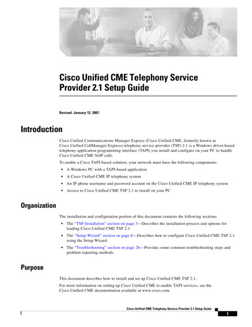
Architecture and ScalabilityPhone localization settingsUC Monitor supports the following settings. Other settings may work, but have notbeen tested. English (US and UK) German, Danish, Dutch Italian, French, SpanishJapaneseArchitecture and ScalabilityArchitectureFor Cisco SPAN deployments, UC Monitor requires a management console and at leastone collector. In general, one UC Monitor collector is required for every switch thathandles call setup flows from the CUCM call server.A standalone UC Monitor system is sufficient for Cisco CDR deployments, small SPANdeployments, or initial rollouts with only one CUCM cluster.A distributed UC Monitor system is recommended for larger SPAN deployments.The following diagram illustrates UC Monitor in a CUCM deployment that includes theSPAN and CDR methods* of data collection:*Although enabling both collection methods simultaneously is not recommended, weinclude them here to illustrate their placement in the deployment.12 CA Unified Communications Monitor
Architecture and ScalabilityScalabilityCisco recommends that you deploy CUCM so as to ensure failover capability andprocessing redundancy: Do not allow the members of a call server cluster to share a VLAN or switch. Use different access switches. Connect them to the same distribution or coreswitch, or to different distribution or core switches. Place call servers in different buildings within the same LAN or WAN.Chapter 1: Introduction 13
Chapter 2: Configuration TasksThis section contains the following topics:Connecting the Collector to a SPAN Port (see page 15)Configuring the Management Console as an FTP Recipient (see page 17)Enabling the Call Stats Setting (see page 18)Enable the Collection of Voice Quality Metrics (see page 19)Enabling Web Access and RTCP for IP Phones (see page 19)Connecting the Collector to a SPAN PortIn a Cisco environment, you can connect the collector to a SPAN port on the switchesthat carry VoIP traffic on your network. The collector must be able to inspect callsetup-related packets that pass between the call servers and endpoints in your system.Connect the collector at an appropriate network location, using a properly configuredSPAN switch port.If possible, SPAN only VoIP traffic and call server traffic Add VLANs dedicated to voice traffic to the list of spanned ports. Configure an ACL to discard non-VoIP traffic before it is sent out of the SPANport. An ACL has significant overhead on some switches, so use your bestjudgment in selecting a method to separate traffic. Use a VACL to filter for all traffic going to and from the IP addresses of the CiscoUnified Communication Managers.Install UC Monitor collectors near monitored call servers or voice gatewaysCalculations for server response times assume that the collector and the monitoredserver receive an inbound frame at approximately the same time. Similarly,traceroute investigations provide the most accurate path results when the collectoris located close to the call server. The collector and call server share a router. Thisconfiguration helps ensure that traceroute results reflect the path taken by packetssent to and from the call server.Consider NIC usageA distributed collector and a standalone server use one NIC for the collector serviceand one NIC for management.When a network tap is used, one NIC is used for management and two NICs areused for the collector service. A tap splits the transmitting and receiving flows of afull-duplex link across two physical ports. The collector receives the separatedtraffic from both NICs.Chapter 2: Configuration Tasks 15
Connecting the Collector to a SPAN PortThe collector works better with SPAN ports than with network tapsPlug the monitor NIC on the collector into the SPAN port. Configure a network taponly when the SPAN port is in use. You can configure remote spanning of switchtraffic to another switch and connect the collector to the SPAN port on the remoteswitch. Having a dedicated collector for each switch is the recommendedconfiguration.Forward the following VoIP protocols to the collector: SIP. Session Initiation Protocol performs call setup and teardown, managessessions, and determines user location, availability, and capabilities. ForwardTCP and UDP traffic on port 5060 to the collector to get SIP flows. UC Monitorsupports authenticated SIP flows, but it cannot interpret or report on calls fromencrypted SIP flows.Note: Collectors can monitor only one port per protocol. To monitor multipleSIP ports on a single SPAN, contact CA Technical Support. H.323. This family of protocols supports real-time transfer of data over packetnetworks by enabling communications between H.323-enabled devices, such asVoIP gateways. Forward the following traffic to the collector:–for H.225, TCP traffic on port 1720–for H.245, TCP traffic on ports above 11000 (dynamically selected) SCCP. The Skinny Call Control Protocol is a proprietary Cisco protocol used formessaging between skinny clients and a Cisco Unified CommunicationsManager. Forward TCP traffic on port 2000 to the collector to get SCCP flows. IfSCCP signaling flows are encrypted, UC Monitor cannot interpret or report oncalls. MGCP. The Media Gateway Control Protocol enables call-control devices, suchas media gateway controllers, to control VoIP calls. Performs similar functionsto H.323. Forward UDP traffic on port 2427 to the collector to get MGCP flows. Q.931. Call setup traffic is backhauled over a TCP connection to Cisco UnifiedCommunications Manager to control the ISDN PRI for the voice gateway. Thecollector must see the Q.931 Setup and Alerting messages that are sentbetween the Unified Communications Manager and the gateway. Forward TCPtraffic on port 2428 to the collector to get the PRI backhaul flows.Verify that the SPAN port is not congested or misconfiguredReview the dropped packets statistics on the SPAN port where you want to connectthe collector.16 CA Unified Communications Monitor
Configuring the Management Console as an FTP RecipientIf you are running CA Application Delivery Analysis on the network, connect CAApplication Delivery Analysis to a SPAN port on a different switchIn some situations, however, both systems must monitor the same switch.Therefore, you can use a network tap to separate the traffic intended for CAApplication Delivery Analysis from the traffic intended for UC Monitor. The collectorcan be connected to a standard tap (copper or fiber) or an aggregating tap ratherthan a SPAN port. CA Application Delivery Analysis supports a dual-NIC collector,which a standard tap requires. UC Monitor does not support this type of collector.Purchase a tap that sends the request and the response traffic over the sameconnection on the tap.Consider traffic from Publishers and SubscribersCisco Unified Communications Manager servers act in multiple roles to providefailover and load balancing capabilities. Therefore, configure the SPAN port so thatVoIP-related traffic is associated with both Publishers and Subscribers.Voice gateways can register with either the Publisher or Subscriber and are oftenconfigured to perform failover duties. Signaling between a voice gateway and a callserver must reach the collector so that all call traffic on the network is monitored.In a large Cisco deployment, each cluster typically includes as many as four servers:one Publisher, two Subscribers to handle call processing, and one TFTP server. ThePublisher and TFTP server act as backups for failover situations. In such aconfiguration, SPAN the traffic that goes to two of the servers in the cluster andsend it to one collector. Then, send the traffic for the other two servers to a secondcollector. If the phones are load-balanced among the servers in the cluster, eachcollector sees data from only half the phones, which is a manageable load.For more information, see the Best Practices for Data Acquisition guide in the CA UnifiedCommunications Monitor bookshelf on the About page of the management console.Configuring the Management Console as an FTP RecipientFor the CDR method, use the Cisco Unified Serviceability web interface to configure themanagement console server as the FTP recipient.Follow these steps:1.Log in to the Cisco Unified Serviceability web interface.2.Click Tools, CDR Management.3.In the Billing Application Server Parameters section, click 'Add new'.Chapter 2: Configuration Tasks 17
Enabling the Call Stats Setting4.5.Complete the parameters as appropriate for your environment. UC Monitorsupports the following default parameter values: Host Name/IP Address. The IP address of the management console server. User Name. anonymous Password. The email address associated with the anonymous user name. Protocol. FTP Directory Path. /Cisco/. Do not forget to include the final forward slash.Click Add.Notes: The UC Monitor installation process creates an FTP site on the managementconsole that allows anonymous users to log in. For secure FTP, you can configureany server as the secure FTP recipient. That server must push the CDRs and CMRs tothe following location on the management console:install directory\VoIPMonitor\FTPSite\Cisco UC Monitor support for the CDR method requires the CA UCM FTP site to beenabled. The installation creates the \VoipMonitor\FTPSite\Cisco folder regardlessof the enabled or disabled status of FTP, and does not overwrite the existing FTPconfiguration. If you disabled the FTP site for a previous release of UC Monitor,then re-enable the site to facilitate support for the CDR method. Similarly,re-enable the site if you disabled it because you did not need Cisco CDR support,but you do want FTP to support another vendor. As a best practice, assign unique Cluster IDs when you have multiple clusters.Unique IDs guard against duplicate FTP filenames; CDRs use the Cluster ID in theFTP filename. Duplicate filenames can result in loss of data at the managementconsole when one CDR is overwritten by another CDR with the same filename. Youcan assign Cluster IDs in the Enterprise Parameters Configuration section of theCisco Unified CM Administration web interface.Enabling the Call Stats SettingPhones that use the Session Initiation Protocol (SIP) return quality metrics only whenyou enable the Call Stats setting in the Cisco Unified CM Administration web interface.You can change the standard SIP profile or you can create a new voice-quality-enabledprofile.After you enable the Call Stats setting on the SIP Profile Configuration window (Device,Device Settings, SIP Profile), apply the new or edited profile to your IP phones.For information about editing or creating SIP profiles, consult the documentation foryour version of CUCM.18 CA Unified Communications Monitor
Enable the Collection of Voice Quality MetricsEnable the Collection of Voice Quality MetricsFrom the Cisco Unified CM Administration web interface, enable the collection of calldetail records (CDRs) and call management records (CMRs). UC Monitor captures theCMR data from the SPAN of traffic going to and coming from the CUCM. Without theuse of SPAN, the CUCM uses FTP to push CDRs (and CMRs) to the UC Monitormanagement console.Follow these steps:1.From the web interface, perform the following steps for each call server in eachmonitored cluster:a.Set the 'CDR Enabled Flag' service parameter to True.b.Set the 'Call Diagnostics Enabled' service parameter to True.By default, both settings are disabled.You do not need to restart the call server for the change to take effect.Notes: Enable CDR and CMR collection on the call servers in each monitored cluster. Ciscohas the following warning:"Generating CMRs without corresponding CDRs can cause uncontrolled diskspace consumption. Cisco Systems recommends that you always enable CDRswhen CMRs are enabled." For information about using the web interface, consult the documentation for yourversion of CUCM. CUCM may enable archiving of CDRs and CMRs. UC Monitor does not require thearchiving of these records.Enabling Web Access and RTCP for IP PhonesAn IP phone’s internal web server lets other programs access the phone’s web page,which provides configuration and status information that the UC Monitor collector uses.The Web Access parameter on the phone indicates whether the internal web server isenabled.You can disable the Web Access parameter for security reasons. Core monitoringfunctionality for UC Monitor does not require you to enable this setting. However, weencourage you to enable the setting to use the UC Monitor Call Watch feature and toview data about discovered phones.Also, enable the RTCP parameter to allow UC Monitor to obtain latency values fromdiscovered phones.Chapter 2: Configuration Tasks 19
Enabling Web Access and RTCP for IP PhonesYou can update 'Phone settings' from the Cisco Unified CM Administration webinterface. For more information, consult the documentation for your version of CiscoUnified Communications Manager.20 CA Unified Communications Monitor
Appendix A: TroubleshootingThis section contains the following topics:Monitoring Authenticated SIP Traffic (see page 21)Add or Remove SIP Ports for Monitoring (see page 21)Monitoring Authenticated SIP TrafficUC Monitor automatically reports on call quality metrics from authenticated SIP trafficby parsing packets that contain Transport Layer Security (TLS) authenticated messages.Cisco Unified Communications Manager uses port 5061 for authenticated SIP traffic.You can use a different SIP port. For more information, see Add or Remove SIP Ports forMonitoring (see page 21).Add or Remove SIP Ports for MonitoringYou can add or remove SIP ports for monitoring. In your environment, firewalls mayprohibit monitoring on the default SIP ports. Or, the needs of your network may requirethat you monitor multiple SIP ports for load balancing, for example.You can change port number in the vcAgentCurrentState.txt file.Follow these steps:1.Open a command-prompt window on the collector server that monitors the SIPports.2.Stop the CA UCM Collector Communication service.net stop “CA UCM Collector”Important: Stop the service before changing the vcAgentCurrentState.txt file.Otherwise, your changes may be overwritten because the collector savesconfiguration settings to the .txt file when it stops.3.After the service stops, navigate to the following location:install directory\voipmonitor\bin4.Open the vcAgentCurrentState.txt file in a text editor such as Notepad.Appendix A: Troubleshooting 21
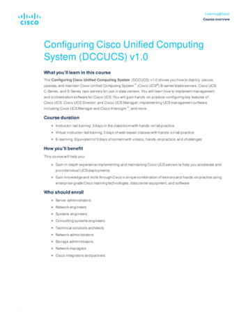
Add or Remove SIP Ports for Monitoring5.In the .txt file, search for text "SIP port " as shown below. Ports 5060 and 5061 aremonitored by default:Changed directives 0x7f009fbeShow summary dialog 0Save interval 1 SCCP port 2000MGCP port 2427Q931 port 2428H225 port 1720SIP port 5060;5061TPKT capture 16.Add or remove port numbers on the SIP port line. Separate port numbers with asemi-colon, but no space. For example: To add port 5066: SIP port 5060;5061;5066 To remove port 5061: SIP port 5060Important: The SIP port line can contain no more than 5 port numbers.7.Save and close the text file.8.In the command-prompt window, start the CA UCM Collector Communicationservice:net start “CA UCM Collector”9.(Optional) To verify your changes, open the voipagent log in theinstall directory\voipmonitor\logs directory.Log entries similar to the following indicate that your changes were 1filters:22 CA Unified Communications MonitorSeverity 4 - [PacketReader] Setting (UDP & TCP) port5060 (SIP).Severity 4 - [PacketReader] Setting (UDP & TCP) port5061 (SIP-2).Severity 4 - [PacketReader] Setting (UDP & TCP) port5066 (SIP-3).
IndexAarchitecture 12authenticated SIP traffic, monitoring 21Bbilling application server parameters 17Ccall diagnostics enabled flag 19call stats setting 18CDR enabled flag 19Cisco environmentsarchitecture 12CDRs & CMRs 7, 19FTP configuration 17scalability 12SIP ports 21SIP profile 18SPAN port configuration 7, 15web server 19FFTP configuration 17Mmetric collection, enabling 19RRTCP parameter 19Sscalability 12SIP ports, adding or removing 21SPAN ports, configuring 15supported CUCM versions 10Wweb access parameter 19Index 23
Cisco Unified Personal Communicator, version 7.0 Call volume data is obtained for calls to and from this client, such as when the calls were made and the locations of the endpoints. Call setup failures can be reported from this client. Medianet-enabled devices UC Monitor supports Cisco