Transcription
AFRL-ML-WP-TR-2000-4037AN ADVANCED NDE TECHNIQUE FORAGILE MANUFACTURINGJEREL A. SMITH and ROBERT S. FRANKLEADVANCED RESEARCH AND APPLICATIONS CORPORATION (ARACOR)425 LAKESIDE DRIVESUNNYVALE, CA 94086-4701FEBRUARY 2000FINAL REPORT FOR PERIOD 01 AUGUST 1995 - 01 APRIL 1999Approved for public release; distribution is unlimited.MATERIALS AND MANUFACTURING DIRECTORATEAIR FORCE RESEARCH LABORATORYAIR FORCE MATERIEL COMMANDWRIGHT-PATTERSON AIR FORCE BASE, OH 45433-7750
Form SF298 Citation DataReport Date("DD MON YYYY")00022000Report TypeFinalTitle and SubtitleAn Advanced NDE Technique for Agile ManufacturingDates Covered (from. to)("DD MON YYYY")01081995 01041999Contract or Grant NumberProgram Element NumberAuthorsSmith, Jerel A.; Frankle, Robert S.Project NumberTask NumberWork Unit NumberPerforming Organization Name(s) and Address(es)Advanced Research and Applications Corporation (ARACOR)425 Lakeside Drive Sunnyvale, CA 94086-4701Performing OrganizationNumber(s)Sponsoring/Monitoring Agency Name(s) and Address(es)Materials and Manufacturing Directorate Air Force ResearchLaboratory Air Force Materiel Command Wright-Patterson AirForce Base, OH 45433-7750 POC: Thomas Moran,AFRL/MLLP, (937) 255-9800Monitoring Agency AcronymMonitoring Agency ReportNumber(s)Distribution/Availability StatementApproved for public release, distribution unlimitedSupplementary NotesAbstractSubject TermsDocument ClassificationunclassifiedClassification of SF298unclassifiedClassification of AbstractunclassifiedLimitation of AbstractunlimitedNumber of Pages54
NOTICEWHEN GOVERNMENT DRAWINGS, SPECIFICATIONS, OR OTHER DATA ARE USEDFOR ANY PURPOSE OTHER THAN IN CONNECTION WITH A DEFINITELYGOVERNMENT-RELATED PROCUREMENT, THE UNITED STATES GOVERNMENTINCURS NO RESPONSIBILITY OR ANY OBLIGATION WHATSOEVER. THE FACTTHAT THE GOVERNMENT MAY HAVE FORMULATED OR IN ANY WAY SUPPLIEDTHE SAID DRAWINGS, SPECIFICATIONS, OR OTHER DATA, IS NOT TO BEREGARDED BY IMPLICATION OR OTHERWISE IN ANY MANNER CONSTRUED, ASLICENSING THE HOLDER OR ANY OTHER PERSON OR CORPORATION, OR ASCONVEYING ANY RIGHTS OR PERMISSION TO MANUFACTURE, USE, OR SELL ANYPATENTED INVENTION THAT MAY IN ANY WAY BE RELATED THERETO.THIS REPORT IS RELEASABLE TO THE NATIONAL TECHNICAL INFORMATIONSERVICE (NTIS). AT NTIS, IT WILL BE AVAILABLE TO THE GENERAL PUBLIC,INCLUDING FOREIGN NATIONS.THIS TECHNICAL REPORT HAS BEEN REVIEWED AND IS APPROVED FORPUBLICATION.CvvLX*THOMAS J MORAN, Project EngineerNondestructive Evaluations BranchMetals, Ceramics & NDE DivisionIES C. MALAS, ChiefNondestructive Evaluations BranchMetals, Ceramics & NDE Division CJ?-GERALD J.K, Assistant ChiefMetals, Cera, es & NDE DivisionMaterials & anufacturihg DirectorateCOPIES OF THIS REPORT SHOULD NOT BE RETURNED UNLESS RETURN ISREQUIRED BY SECURITY CONSIDERATIONS, CONTRACTUAL OBLIGATIONS, ORNOTICE ON A SPECIFIC DOCUMENT.
Form ApprovedOMB No. 074-0188REPORT DOCUMENTATION PAGEPublic reporting burden for this collection of information is estimated to average 1 hour per response, including the time for reviewing instructions, searching existing data sources, gathering andmaintaining the data needed, and completing and reviewing this collection of information. Send comments regarding this burden estimate or any other aspect of this collection of information, includingsuggestions for reducing this burden to Washington Headquarters Services, Directorate for Information Operations and Reports, 1215 Jefferson Davis Highway, Suite 1204, Arlington, VA 22202-4302,and to the Office of Management and Budget, Paperwork Reduction Project (0704-0188), Washington, DC 205031. AGENCY USE ONLY2. REPORT DATE(Leave blank)3. REPORT TYPE AND DATES COVEREDFebruary 20004. TITLE AND SUBTITLEFinal 8/1/95 - 4/1/995. FUNDING NUMBERSAn Advanced NDE Technique for Agile ManufacturingC F33615-95-2-5239PE 63570EPR C193TA 02WU 016. AUTHOR(S)Jerel A. Smith and Robert S. Frankle7. PERFORMING ORGANIZATION NAME(S) AND ADDRESS(ES)8. PERFORMING ORGANIZATIONREPORT NUMBERAdvanced Research and ApplicationsCorporation (ARACOR)425 Lakeside DriveSunnyvale, CA 94086-4701ARACOR FR942-009. SPONSORING / MONITORING AGENCY NAME(S) AND ADDRESS(ES)10. SPONSORING / MONITORINGAGENCY REPORT NUMBERMaterials and Manufacturing DirectorateAir Force Research LaboratoryAir Force Materiel CommandWright-Patterson Air Force Base, OH 45433-7750POC: Thomas Moran, AFRL/MLLP, (937) 255-9800AFRL-ML-WP-TR-2000-403711. SUPPLEMENTARY NOTES12a. DISTRIBUTION / AVAILABILITY STATEMENT12b. DISTRIBUTION CODEApproved for public release; distribution is unlimited.13. ABSTRACT (Maximum 200 Words)A Konoscope volumetric x-ray computed tomography (CT) system (the Konoscope ) was developed. Unlike conventional CT systems, which acquire data oneslice at a time, the Konoscope acquires all the necessary data at one time. This approach significantly accelerates the collection of the CT data required for imageproduction, especially for high-resolution scanning. The Konoscope employs an x-ray cone beam and an area detector, rather than the fan beam and linear detectorused in conventional CT systems. Technological advancements made during the project and incorporated in the Konoscope include: a bright x-ray source using anARACOR diamond anode bright anode transmission target (BRATT ); a high-performance area detector; a helical scan geometry for acquiring volumetric CT data;and the parallel processing of optimized reconstruction software for timely reconstruction of large, volumetric data sets. The Konoscope , which is housed in a fullyshielded cabinet, can inspect an object 100 mm to 200 mm in diameter at a maximum resolution of 250 µm. Part dimensions can be measured with an estimatedaccuracy of 25 µm. Creating volumetric CT images with the Konoscope is significantly faster than with conventional 2-D CT systems. The Konoscope iscapable of supporting the most demanding CT applications, such as metrology and reverse engineering, which require data with the highest accuracy and resolution.The Konoscope is uniquely qualified to nondestructively capture 3-D part geometry, which is an essential component of agile manufacturing.14. SUBJECT TERMS,15. NUMBER OF PAGESComputed tomography, agile manufacturing, nondestructive evaluation, x-ray16. PRICE CODE17. SECURITY CLASSIFICATIONOF REPORT20. LIMITATION OF ABSTRACT58Unclassified18. SECURITY CLASSIIFICATION OF THIS PAGE19. SECURITY CLASSIFICATIONOF ABSTRACTUnclassifiedUnclassifiedNSN 7540-01-280-5500SARStandard Form 298 (Rev. 2-89)Prescribed by ANSI Std. Z39-18298-102i
TABLE OF CONTENTSPageLIST OF FIGURES .ivLIST OF TABLES .vACKNOWLEDGEMENT.vi1.0EXECUTIVE SUMMARY .12.0MOTIVATION .23.04.02.1AGILE MANUFACTURING .22.2CT- BASED REVERSE ENGINEERING.3TECHNICAL APPROACH.53.1BRIGHT X- RAY SOURCE .63.2AREA DETECTOR .73.3VOLUMETRIC SCAN GEOMETRY.83.4RECONSTRUCTION OF 3-D DATA SETS.8THE KONOSCOPE.94.1OPERATION .94.2PERFORMANCE .144.3EXAMPLES .154.3.1 Chambered Nautilus Shell .164.3.2 Aluminum Casting .164.3.3 Graphite Composite Test Sample .165.0CONCLUSIONS.21APPENDIX A. Konoscope Description .22APPENDIX B. Konoscope Presentation .24iii
LIST OF FIGURESFigurePage1CT-Assisted Reverse Engineering of a Gearbox Cover Sand Casting .42Cone Beam CT System.53The Konoscope .104The Object Handling System Looking Toward the X-ray Source.105The Object Handling System Looking Toward the Detector .116Konoscope Source-to-Scintillator Geometry.137Konoscope Detector .138CT Slice of the Chambered Nautilus Shell .179Volumetric Image of the Chambered Nautilus Shell .1710Photograph and Volumetric Image of the Aluminum Casting .1811Photograph of the Graphite Composite Test Sample.1812Volumetric Image of the Composite Test Sample CT Data .1913Density Variation and Cracks in the Composite Test Sample .1914Inclusions in the Composite Test Sample .20iv
LIST OF TABLESTablePage1Design Performance Targets .62Konoscope Components .123Scan Geometries and Reconstruction Algorithms .144Konoscope Performance .145Scan and Reconstruction Time .156File Sizes.15v
ACKNOWLEDGEMENTThe majority of the development of the Konoscope x-ray computed tomography system wasperformed under a cooperative agreement with the Defense Advanced Research Projects Agency(DARPA) and the Air Force Research Laboratory (AFRL) under Air Force Contract NumberF33615-95-2-5239. Additional support was provided by the State of California CompetitiveTechnologies Program (C95-0127), the National Science Foundation (NSF) (DMI-962-8968),and ARACOR.ARACOR would like to acknowledge the contributions of Dr. Thomas J. Moran, the Air ForceTechnical Monitor, and thank him for his support.vi
1.0EXECUTIVE SUMMARYIn this project, ARACOR developed the Konoscope volumetric x-ray computed tomography(CT) system (the Konoscope). Unlike conventional CT systems, which acquire data one slice ata-time, the Konoscope acquires all the necessary data at one time. This approach significantlyaccelerates the collection of the CT data required for image production, especially for highresolution scanning. The Konoscope employs an x-ray cone beam and an area detector, ratherthan the fan beam and linear detector used in conventional CT systems.Technologicaladvancements made during the project and incorporated in the Konoscope include:1. A bright x-ray source using an ARACOR diamond anode BRATT (BRight AnodeTransmission Target) target2. A high-performance area detector3. A helical scan geometry for acquiring volumetric CT data4. The parallel processing of optimized reconstruction software for timely reconstruction oflarge, volumetric data sets.The Konoscope, which is housed in a fully shielded cabinet, can inspect an object 100 mm to200 mm in diameter at a maximum resolution of 250 µm. Part dimensions can be measured withan estimated accuracy of 25 µm.Creating volumetric CT images with the Konoscope issignificantly faster than with conventional 2-D CT systems. In one day, three parts can bescanned and 512 x 512 x 512 volumetric images produced. Even a 1024 x 1024 x 1024 scan ofone part can be completed in one day.The Konoscope is capable of supporting the mostdemanding CT applications, such as metrology and reverse engineering, which require data withthe highest accuracy and resolution. The Konoscope is uniquely qualified to nondestructivelycapture 3-D part geometry, which is an essential component of agile manufacturing.1
2.0MOTIVATIONThis project was motivated by the need to develop a practical CT system to support highresolution imaging applications, especially metrology and reverse engineering.Withconventional 2-D CT, which acquires data one slice at-a-time, scanning an entire part at thehighest available resolution can be a time-consuming process. Attempts have been made atdeveloping 3-D (volumetric) CT systems, where an entire volume of data is acquired at one time,rather than slice-by-slice. Although these initial volumetric CT systems were faster than 2-Dscanners, they could not achieve the required resolution. A CT system was needed with theresolution of 2-D CT and the inspection speed of volumetric CT. The Konoscope developed inthis project is such a system.2.1AGILE M ANUFACTURINGAs its name implies, agile manufacturing has been defined as the ability to make any part at anytime in any quantity for any customer.The key to achieving agile manufacturing is thedevelopment of practical, fully- integrated computer-based capabilities to define, design,engineer, and manufacture parts, including: Accurately and rapidly define 3-D part geometry (inspection). Compare part geometry with design requirements (metrology). Create an accurate digital computer aided design (CAD) model of the part. Predict part response to operational loads and environments using computer aidedengineering (CAE). Reproduce a part from its CAD model using computer aided manufacturing (CAM)and rapid prototyping techniques.One application of agile manufacturing is the production of spares for aging aircraft. The U.S.Air Force has a large number of older aircraft that are expected to be the backbone of the totaloperational force for the foreseeable future. To support the extended lifetimes for these aircraft,the spare parts pool must be replenished. Furthermore, an initial complement of spares must beestablished for parts that were never envisioned for replacement.When spares need to befabricated, they are typically purchased from the Original Equipment Manufacturer (OEM) oranother third-party vendor qualified to produce the part.2
Production of spares for aging aircraft is often problematic because the required technical datapackages (drawings and/or CAD files) for needed spare parts are unavailable or incomplete.When the technical data package is missing or incomplete, reverse engineering can be used to1) measure the part to define its three-dimensional geometry, 2) create engineering drawingsand/or a CAD model, and 3) fabricate additional parts. In conventional reverse engineering,which can be time consuming and labor intensive, the external surface of a part is measuredusing manual techniques and machines, such as a coordinate measuring machine (CMM) or alaser scanner. A part must be destroyed and sectioned to measure its internal geometry.2.2CT-BASED R EVERSE ENGINEERINGARACOR has developed CT-based Reverse Engineering, Metrology, and Part Production(REMAPP ) technology. Using this technology, CT data are acquired from the entire part andconverted to a 3-D “point cloud,” which defines the 3-D part geometry. The point cloud data areused to produce a CAD model of the part, from which internal and external dimensions areobtained.Beginning with the CAD model, parts can be fabricated with computer-aidedmanufacturing (CAM) techniques, such as numerically controlled machining and rapidprototyping methods.CT-based reverse engineering offers many adva ntages over conventional methods, especially forcomplex parts with internal structure: Provides a dense data set for accurate measurement regardless of part complexity Produces a digital dataset that can be input directly to CAD/CAE/CAM software Fully nondestructive, non-contact method without risk to fragile parts Insensitive to surface condition or finish Set-up is the same regardless of part geometry Can be highly automated with limited manual laborThe Konoscope is uniquely qualified to nondestructively capture 3-D part geometry, which isessential for the REMAPP process and agile manufacturing.ARACOR has demonstrated the technical and economic value of REMAPP technology for lowcost, efficient manufacturing of metal castings. In one project, the REMAPP process was used todesign tooling to cast a steering gearbox cover from the Marine Amphibious Assault Vehicle, as3
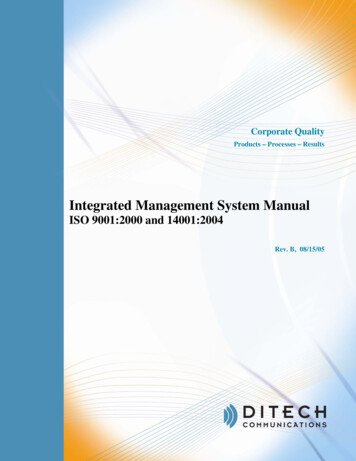
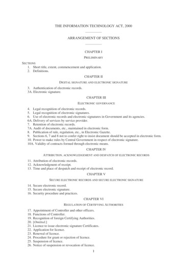
illustrated in Figure 1. A CAD model of the cover was created from a CT inspection of anexemplar cover. Three of the resulting CT images are shown in Figure 1. Both the internal andexternal surfaces are visible in the point cloud derived from the CT data, Figure 1d. The CADmodel constructed from the point cloud data is shown in Figure 1e. A sand mold for casting thepart was fabricated using a CAD model of the core, shown in Figure 1f, which was also derivedfrom the CT data. A replica gearbox cover was successfully cast using the REMAPP process.Cost and time savings up to 50% of conventional methods were obtained and the dimensionalaccuracy was adequate to meet metal casting tolerance requirements.a) CT Image 1b) CT Image 2c) CT Image 3N, - -'i."# d) CT -Derived Point Cloude) CAD Solid Model of Castingf) CAD Solid Model of CoreFigure 1. CT-Assisted Reverse Engineering of a Gearbox Cover Sand Casting4
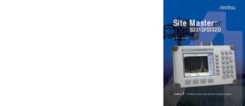
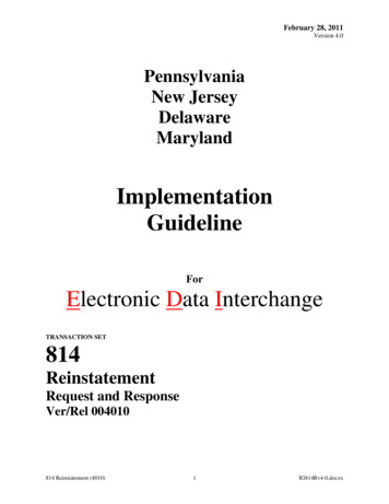
3.0TECHNICAL APPROACHThe objective of this project was to develop a volumetric CT system with the resolution of aconventional 2-D CT system and the speed of a volumetric system. To meet this objective,ARACOR developed a cone-beam CT system, illustrated in Figure 2. With cone-beam CT, thex-ray beam emerges from the source in a conical shape. The x rays travel through the object andimpinge on the area detector.simultaneously.The entire part of interest is illuminated and inspectedThe views of the object required for CT reconstruction are acquired byappropriate rotation and translation.Area DetectorX-ray SourceFigure 2. Cone Beam CT System5
Table 1 lists the design performance targets that were defined during the project for thevolumetric CT system.Table 1. Design Performance TargetsValueFeature50 mmField of View250 mmField of ViewImage Size512 x 512 x 512512 x 512 x 512Pixel Size0.1 mm0.5 mmResolution (FWHM*)0.2 mm1.0 mm0.025 mm0.050 mmDimensioning Accuracy* Full width half maxAchievement of these performance targets in the cone-beam CT system depended on developingand integrating a number of specific technical improvements: A bright x-ray source A high-performance area detector A scan geometry to acquire high-resolution, volumetric CT data A methodology for reconstructing large, 3-D data setsEach of these improvements was accomplished during the project, as described in Sections 3.1through 3.4.The original technical approach included a demonstration of the volumetric CT system in aREMAPP application. The plan was to Capture the 3-D geometry of a part using the new volumetric CT system Convert the CT data to a CAD model Define mold tooling and casting process parameters based on CAE Fabricate mold tooling via rapid prototyping Cast a replicate partThe demonstration was cancelled because full funding for the project was not available.3.1BRIGHT X-RAY SOURCEThe bright x-ray source was achieved by purchasing a customized x-ray source from acommercial supplier and integrating it with an ARACOR diamond anode BRATT (BRight6
Anode Transmission Target) target developed for this application. The BRATT target has atransmission geometry with a tungsten target and diamond substrate.Unfortunately, the FeinFocus 225 kV/320W micro-focus x-ray source cannot be operated at fullcapacity for any reasonable length of time.It shuts down periodically and displays thediagnostic message, “Generator Breakdown.” The problem appears to be caused by arcing in thex-ray source. The source was returned to FeinFocus and their service technicians spent aconsiderable amount of time at ARACOR. However, all efforts to overcome the problem havebeen unsuccessful. Therefore, the source was de-rated and is being operated at a maximum of160V/200W to reduce the incidence of premature shutdown. For a larger spot size, 300Woperation can be achieved. In spite of the problems with the FeinFocus source, ARACOR’sdiamond anode BRATT target has had stable operation at the reduced power load.In 2-D CT, most of the x rays that are scattered from an object are removed by restrictivecollimation at the detector. Because detector-side collimation is not practical in 3-D CT, scatterfrom an object can significantly degrade image contrast. Therefore, ARACOR incorporatedsource-side slice collimators in the volumetric CT system to reduce the amount of scatter in theimage. The effectiveness of these collimators has not been quantitatively measured.3.2AREA D ETECTORThe volumetric CT system utilizes a 3-D cone beam rather than a 2-D fan beam of x rays.Therefore, the system requires an area detector with scatter-rejection capability, superior contrastsensitivity and dimensional accuracy. Components of the area detector include a CCD cameraand optics, fluorescent screen (scintillator), and scan control software.An appropriatecommercial CCD camera and lens were purchased for the area detector. For different sizedobjects, the camera and optics adjust to maximize the number of pixels across the projectedimage of the scanned object. For the Konosocope, the largest object (200- mm diameter) wouldbe projected to about 265 mm on the scintillator, while the projection of the smallest object(100-mm diameter) would only be half as large. Therefore, the CCD camera in the Konoscopecan “zoom” in or out so that the projected image will fill the 1024 x 1024 optical field of thecamera. As a result, the highest resolution is achievable for the full range of object sizes. Aconvenient, semi-automated technique was developed to recalibrate the system followingchanges in the field of view.7
The scintillator was initially designed as a CsI (Tl) fluorescent screen. However, problems wereencountered fabricating a high-quality CsI (T1) one-piece or tiled screen that did not produceartifacts in the CT data. When these problems could not be overcome, a Gd 2 O2 S:Tb screen wassuccessfully fabricated. The Gd 2 O2 S:Tb screen has the required quality and uniformity, altho ughit has lower brightness and x ray stopping power than the CsI (T1) design.3.3VOLUMETRIC SCAN G EOMETRYFundamental to the volumetric CT system is the ability to acquire 3-D CT data, rather than dataone slice at-a-time. This required the development of a volumetric scan geometry, i.e., a way tomove the part relative to the x-ray source to obtain the required volumetric image data. Theoriginal plan to combine two, orthogonal scans proved unworkable.A novel helical scangeometry was subsequently devised. During a helical scan, the object is rotated and translatedsimultaneously, rather than the conventional rotate-translate 2-D CT motion. The advantage of ahelical scan is that the scan motion is easy to implement, does not involve repositioning the part,and generates a complete data set.3.4RECONSTRUCTION OF 3-D DATA S ETSThe 3-D CT system produces very large data sets that must be reconstructed to produce the CTimages. Timely reconstruction requires computer hardware and software optimized to treat thelarge data sets. The initial approach was to develop specially designed accelerator boards for thereconstruction workstation. Lawrence Livermore National Laboratories (LLNL) was tasked touse their Image Matrix Processor technology to develop and fabricate the boards under fundingfrom a separate project. Unfortunately, LLNL delayed implementing their project so long that itcould not provide timely inputs to this project. Therefore, development of the accelerator boardswas abandoned.Fortunately, an alternate approach was successful in achieving significant reductions inreconstruction time for 3-D CT data sets. In a cooperative effort with NSF, ARACOR usedmultithreaded programming to create improved reconstruction software that is optimized forparallel processing. The resulting reconstruction software, running on a workstation with fourprocessors, ran three times faster than previously achievable.8
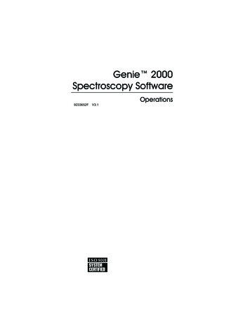
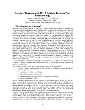
4.0THE KONOSCOPEThe volumetric CT system developed in this project was named the “Konoscope” fromthe Greek words konos, “cone,” and scope, “to look.” A photograph of the Konoscope isshown in Figure 3.The entire system is enclosed in a shielded cabinet measuringapproximately 8-feet long x 3- feet wide x 6- feet high. The cabinet is designed to provideeasy access to the system for convenient operation and maintenance. Figure 3 showsthree compartments that contain the three primary subsystems: the x-ray source in the leftcompartment, the precision object handling system in the middle compartment, and thearea detector in the right compartment. Each compartment is accessed by sliding a leaddoor, as shown in Figure 3. A view of the object handling system looking toward the xray source is shown in Figure 4 and one looking toward the detector is shown in Figure 5.Notice the source-side collimation slits in Figure 4. There are also three computers usedfor 1) scan control, 2) reconstruction, and 3) analysis, as well as software for eachfunction. The system components are described in Table 2.A description of the Konoscope is included as Appendix A to this report. Appendix B isa hardcopy of a presentation describing the Konsocope, which will be used to publicizethis new CT system.4.1OPERATIONThe geometry of the source, object handling system and scintillator are shown in Figure6. The precision handling system provides the capability to move the object in a varietyof ways, including helical and conventional rotate-only motions. The area detectorcomponents are illustrated schematically in Figure 7. By varying the camera’s field ofview, the system can be configured to image objects between 100 mm and 200 mm indiameter.A semi- automated technique is used to recalibrate the system followingchanges in the field of view.9
Figure 3. The KonoscopeFigure 4. The Object Handling System Looking Toward the X-ray Source10
Figure 5. The Object Handling System Looking Toward the Detector11
Table 2. Konoscope ComponentsComponentDescriptionX-ray Source FeinFocus Model FXS-225.50Demountable microfocus source160 kV (derated) and 300 W maximum5 µm – 1 mm adjustable spot sizeARACOR diamond anode BRATT targetObject Handling System Dover airbearing tables360 rotation295-mm elevation6-µm position accuracyScreen 350 mm x 350 mmGd 2 O2 S:TbCamera and Optics Photometric PXL W/10242 CCD 16 bit digital cameraCanon EF 50mm f/1.0 lensEnclosure 8.5 ft x 2.9 ft x 6.0 ftCabinet with built-in shieldingScan Control Computer Apple Macintosh 7600/132128 MB RAM1.2 GB hard drive17 GB hard driveIP Lab Spectrum image display/analysis softwareNational Instruments LabView-based control softwareARACOR LVCam camera interface softwareAnalysis Computer Silicon Graphics Indigo 2R10000 CPU2 MB Cache128 MB RAM4 GB hard drive250 MHz clock speedReconstruction Computer Silicon Graphics Origin 2004 CPUs2 GB RAM54 GB Disk12
550 mm415 mm, Mag - 1.325ScintillatorθmaxSource250-mmL scint - 360 mmField-of-View 17.5 Low-densitySpacerRotary TableZ tableVariable Field-of-ViewFigure 6. Konoscope Source-to-Scintillator GeometryMirrorZoomLensScintillatorCCD CameraMobile ChassisFigure 7. Konoscope DetectorThe Konoscope provides the flexibility to perform CT scans with different resolutions, scangeometries, and reconstruction algorithms. Table 3 lists the available combinations of thesecapabilities.13
Table 3. Scan Geometries and Reconstruction AlgorithmsResolutionScan Geometry512102420482-D Rotate OnlyXXX3-D Rotate OnlyXX3-D HelicalXXXXXIFRT 1XXXBack ProjectionXXFeldkampXXHelical FeldkampXXReconstruction AlgorithmVOIR2124.2Inverse Fourier Reconstruction TechniqueARACOR’s Volumetric Image Reconstruction algorithmPERFORMANCETable 4 summarizes the performance of the Konoscope based on scans of resolution phantoms.The actual performance can be compared with the design targets listed in Table 1.Table 4. Konoscope PerformanceValueFeature100 mmField of View200 mmField of ViewImage Size1024 x 1024 x 10241024 x 1024 x 1024Pixel Size0.1 mm0.2 mmResolution (FWHM*)0.25 mm0.45 mm0.025 mm*0.050 mm*Dimensioning Accuracy* estimate
425 lakeside drive sunnyvale, ca 94086-4701 february 2000 final report for period 01 august 1995 - 01 april 1999 materials and manufacturing directorate air force research laboratory air force materiel command wright-patterson air force base, oh 45433-775