Transcription
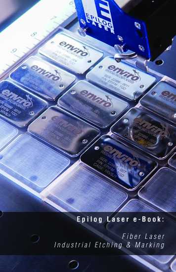
Fiber Laser Industrial Etching & Marking e-Book
Table Of ContentsIntroduction 2How a Fiber Laser Works 3Compatible Materials 4Non-Compatible Materials 5Types of Marks 6Commonly Marked Products 7How to Engrave with a Fiber Laser System 8General Processing Guidelines 10How to Reduce Overall Cycle Times 11Having Trouble? Be Creative! 12FAQ on Fiber Laser Systems 13General Metal Engraving 16Suggested Material Settings 16Annealing & Polishing of Metals 21Deep Metal Engraving 23General Plastic Marking Guidelines 27Vector Scoring/Cutting Guidelines 29Common Types of Stainless Steel 31Common Types of Aluminum 36Technical Specifications 40Dual Source Configurations 41What is a Laser and The Different Types 43Glossary of Laser Terminology 48Glossary of Industry Terminology 51How to Get More Information 53 2016 Epilog Laser1
IntroductionThe fiber laser has been a great tool for our customers because it meets anentirely new set of needs. The ability to etch and mark so many types of industrialproducts means that you have the challenging task of determining how tobest test the materials to show off how well the laser will work for a particularapplication.To help you determine if a fiber laser system is right for your application, we’veput together a short white paper which will:Provide you with a list of the most common compatible and non-compatiblematerials for the fiber laser source. Help you determine the correct printing parameters when etching differentmaterials. Give you a quick reference guide when thinking about applications for thefiber laser system.2 Fiber Laser Industrial Etching & Marking e-Book
How a Fiber Laser WorksThe Short Answer: The fiber laser source generates a laser beam by pumpingintense diode light into the end of fiber optic cables that have been doped withytterbium. The energy from the diode light is absorbed by the ytterbium in thefiber optic cables. The ytterbium then releases the energy in the form of photonsthat travel down the optic cables. The photons that leave the optic cables createthe laser beam. The wavelength of light generated from a fiber laser is 1062 nm.The Longer Answer: The fiber laser source generates laser light by pumpingintense diode light into fiber optics cables that are doped with the rare-earthelement, ytterbium (Yb3 ), which is referred to as the medium or gain medium.As this diode light energy travels into the fiber optic cable, it energizes theelectrons in the ytterbium and the ytterbium electrons go from a ground or stablestate, to an excited state.Essentially, all that is happening in this first step is that the electrons in themedium are absorbing and storing the energy that’s coming from the externalenergy source (diodes). In the fiber laser (and also most YAG lasers these daysand YVO lasers) the external energy source is a laser diode.The electrons in the medium don’t really want to store the external energy they’veabsorbed, so they emit the extra energy by releasing a photon (a quantum packetof light). Once a photon has been emitted by one electron in the medium itstimulates other excited electrons to also emit photons, creating a chain reactionwhere the absorption and emission of energy is at a constant rate. The photonstravel through the optic fibers and some are released through the end of the fibersas the laser beam.By continually pumping energy into a medium, that medium tries to shed theexcess energy by emitting photons. The type of medium is important becausedifferent mediums absorb different types of energy (for instance, a CO2 gasmedium is not going to absorb the energy from a diode in a way that will make theCO2 gas lase). Different mediums also emit different wavelengths of photons, andhence, the different properties of different wavelength lasers. 2016 Epilog Laser3
Compatible MaterialsHere is a list of the compatible materials that we have found work well with thefiber laser system: 17-4 PH stainless steel303 stainless4043 steel6061 AluminumABS (black/white)Aluminum, 6061Aluminum, yellow chromateBayer 2807 Makrolon polycarbonateBayers bayblend FR110Black/white ABSBlack/white polycarbonateBrassBrushed aluminumCarbon fiberCarbon nanotubeCeramics, metal-platedClear coat anodized aluminumCobalt chrome steelColored Delrin (black/brown)Compacted powder iron with ironphosphate coatingCopperDAP- Diallyl PhthalateDelrin, colored (black/brown)GE Plastics polycarbonate resin121-RGlass filled PEEKGlass filled TeflonHard coat anodized aluminumInconel metals (various)Machine tool steel MagnesiumMetal-plated ceramicsMolybdenumNickel plated 1215 mild steelNickel plated brassNickel plated goldNickel plated KovarNickel plated steelNylonPEEK, whitePolybutylene TerephthalatePolycarbonate, (black/white)Polycarbonate resin 121-R, GEPlasticsPolycarbonate, Bayer 2807 MakrolonPolysulphoneRynite PETSantopreneSilicon carbideSilicon steelSilicon wafersStainless steel 303Stainless steel 17-4 PHSteel 4043Steel, machine toolVarious inconel metals (nickelchromium super alloys)White PEEKYellow chromate aluminumZinc plated mild steelIf you have additional questions about these materials, please contact theApplications Lab at applications@epiloglaser.com.4Fiber Laser Industrial Etching & Marking e-Book
Non-Compatible MaterialsInstead of providing a master list of non-compatible materials, we recommendexperimenting using a broad range of settings and different techniques to drawyour own conclusions. Many “non-compatible” materials will actually mark usingthe fiber wavelength of light and our endless range of adjustable settings. Whetherthe mark is desirable, provides enough contrast, or is acceptable for the intendedapplication is all subjective.Transparent polymers often won’t engrave using the fiber wavelength at standardpolymer settings. The beam simply passes right through and marks the table. Itis possible to get a mark on transparent polymers using metal engraving settings,but the results are typically less than stellar. The polymer’s pigmentation alsoplays a role in whether or not it will mark.Delrin: black Delrin marks well, but white Delrin doesn’t mark as well.Organic materials generally aren’t well-suited for the fiber laser system. Wood,clear glass, clear acrylic, leather and fabrics all tend to be transparent to the1062nm wavelength.Suggestions for marking less than ideal materials include: Oxidizers, paint fill and foils can help enhance the mark. Placing a metal plate under a transparent material will result in a mark. Thefiber wavelength will pass through the material, mark the metal plate andreflect the beam back onto the bottom side of the transparent material. Consider using the Cermark or Thermark line of marking compounds as theycan work with the fiber wavelength of light. In many cases, an alternative compatible material can be used. 2016 Epilog Laser5
Types of MarksTerminology used when examining different types of marks:Ablation: The process of ablation is theremoval from the surface of an object byvaporization. You’ll often hear of this processassociated with etching an anodized material.Annealing: This is the process of heating steelto a high temperature, creating a permanentoxide layer on the surface. The mark thatresults is a high-contrast mark created withoutchanging the surface finish of the metal.Color Changing: With some plastics, the laserradiation penetrates the plastic and is absorbedby the color pigments of the plastic. Thepigments are chemically modified, resulting ina color change in the surface, withoutdamaging the surface.Engraving: The material is vaporized by thelaser beam. The result is often a cone-shapedindentation due to the shape of the laser beam.Foaming: Most commonly seen with plasticsand sometimes stainless steel, foaming iswhen melting of the material occurs, producinggas bubbles that get trapped as the targetmaterial cools, producing an elevated result.6Fiber Laser Industrial Etching & Marking e-Book
Commonly Marked ProductsHow do customers most often use a fiber laser for their business? Many enterthe market with one application in mind for use with the laser, but quickly expandthe laser’s usage into a variety of different applications.Barcoding and SerializingA common use for the fiber laser is etching barcodes and serial numbers directlyon parts and tools. The fiber laser provides a very high-quality mark that is easilyread by barcode scanners. You can choose between one-dimensional codes, UPCcodes, data matrix or any other type of code. When you are serializing parts, thelaser is often used in conjunction with a jig that holds multiple parts in the laserand an entire table full of parts are serialized all in one engraving job withouthaving to utilize a dedicated operator to switch out parts.Placing Your Logo on ProductsWhen your company is providing a high-end product, etching your logo directlyon the part guarantees that your brand will always be immediately identifiable bythe customer. Printed labels can be taken off the product, but your logo will bepermanently marked on the product.Customizing Products for CustomersNot only can you brand your parts, but you can also customize your product foryour customer by etching their logo directly on products that you manufacture forthem. When you are able to create a high-end etched logo on the product for yourcustomer, it provides a service that your competitors may not be able to provide,and allows you up-sell to add the logo to the product.These are only a few of the ways that customers are using fiber laser systems, butthere are many more ways to utilize the laser that go beyond these categories aswell. 2016 Epilog Laser7
How to Engrave with a Fiber LaserSystemSoftware InterfaceLaser systems feature two main software interfaces:1.Proprietary Software2.Open Architecture Print DriverBenefits of Proprietary Software: Guaranteed to work with the laser system regardless of updates. Features that are specially designed for processes that are associated withthe laser.Drawbacks of Proprietary Software: Tries to recreate functions that are better handled by professional software. Updates and bug-fixes are company dependent. Have to learn new software to operate the laser and spend time training newoperators on how to run the software.Benefits of Open Architecture Software:You are able to use the most commonly used software (AutoCAD, Illustrator,CorelDRAW, BarTender, etc.) Best-of-breed software tends to be designed with better, more reliable featuresets. Since you are using common software applications, training is relativelysimple. Easier to get support on the software from experts who understand how itoperates.8 Fiber Laser Industrial Etching & Marking e-Book
Drawbacks of Open Architecture Software: Updates to software needs to be tested for operation with the system. Features are built into the print driver instead of the software itself.Epilog’s fiber laser systems utilize an open architecture software interface thatworks through a Windows -based print driver. This allows users to create theirlaser files in a variety of software, such as AutoCAD, and print the file directlyto the laser. All system configurations and settings are set in the print driver,including engraving resolution, frequency, focus, speed, power and more. We findthis provides users with the easiest-to-use design capabilities combined with thedesign versatility of a variety of software choices.Sending a File to the Laser1.To send a file to the laser, in the design software of your choice start by creating anew page the size of the piece you are engraving.2.Import your images, type in text, or place your barcode or serial number and place iton the page just as if you were preparing the file to print to paper.3.Print the file and choose the laser as your printer. In the printer properties youcan choose resolution, speed, power, frequency and focus for the material you areengraving. We provide a chart with suggested settings for a variety of materials.4.Place your item in the top left corner of the engraving table, close the door, and runthe job at the laser.5.If you are engraving multiple items at one time, you can set your page size to the sizeof the engraving table and duplicate your file across the entire page. You can also usea custom cut jig to hold multiple parts. 2016 Epilog Laser9
General Processing GuidelinesProcessing fiber laser system applications isn’t rocket science; however there areseveral tips and tricks to help provide the best possible results.Tools: A pair of calipers and a 7-10X loop.Checklist: Start by reviewing the system requirements and devising a game plan.What process are you looking to replace using a fiber laser? Is there a depthrequirement? Is there an ideal cycle time? Consider the industry; how the partis used; the environment the part will be exposed to; and possible post-markprocessing before deciding on a particular mark.Base Settings: Choose from the base settings we’ve provided in the manual forthe most similar material. Start with small text on an inconspicuous area of thepart.Testing Multiple Marks: As you test different settings, instead of moving the text/artwork around in your graphic design software, use the center positioning featurefor quicker testing.Reduce Browning of the Mark: With any metal, bare or coated, too much poweror too low of frequency will cause a color change (typically light brown at thesurface). Minimize the color change by reducing the power or increasing thefrequency.10Fiber Laser Industrial Etching & Marking e-Book
How to Reduce Overall Cycle TimesHere are a few tips for reducing the overall cycle time when testing a material withthe laser.High Wattage High Speed: For metal applications, use the highest wattageavailable. Epilog Laser provides fiber laser systems with wattages ranging from 20to 50 watts.Lower the Resolution: How important is a high resolution image for yourapplication? Processing jobs at 400 dpi vs. 600 dpi can reduce cycle times by upto 30%, and processing at 300 dpi could mean half the cycle time.Reduce White Space: Orientate the parts to minimize engraving dead space (areawhere head travels, but has nothing to engrave).Don’t Use the Rotary: If an option, run cylindrical parts as flat stock. Orientate theartwork to be inline going across highest point of part.Horizontal Layout: If an option, horizontal text will engrave faster than vertical orcurved (fit text to curve) text.Start with a Higher Speed Setting: Unless necessary, start with a higher speedsetting. 40-60% speed with a frequency of 1-5% will likely yield the same resultsas 20-30% speed using 15-30% frequency.Color Mapping: Use the Color Mapping feature to save time by adjusting the orderin which the objects engrave/mark.Run Multiples: Time studies using a mocked-up bed full of parts will confirm areduction of individual times. 2016 Epilog Laser11
Having Trouble? Be Creative!The list of adjustable parameters is long, so get creative! Don’t settle on justadjusting the speed/power/frequency.Use Multiple Runs: Run an etch pass, then use a second or third pass to clean upor polish the mark.Outline the Mark: Use a vector anneal outline around the text to really make itstand out.Adjust the Focus: For curved parts, focus between the high and low point.Dither to Reduce Discoloring: When running sensitive materials that quicklydiscolor, consider using the Dashboard dithering patterns (Jarvis/Stucki) or a80% gray fill.12Fiber Laser Industrial Etching & Marking e-Book
FAQ on Fiber Laser SystemsQ: What is the laser source of the fiber laser source?A: The source is a fiber laser: a fiber optic cable that has been doped withytterbium, a rare earth element.Q: Is it the same as a YAG (yttrium aluminum garnate) laser?A: It produces the same wavelength of light and same marks. YAG lasers requirecooling and more maintenance.Q: What is the wavelength of the FM?A: 1062 nm.Q: Is the wavelength of light dangerous?A: Yes, especially to the operator’s eyes and will pass through common Lexanor glass materials. The viewing window has been impregnated with an organiccompound that absorbs the fiber energy. If running the systems with the safetyinterlocks defeated, the user MUST wear special safety glasses containing thesame impregnated compound.Q: What is the power consumption?A: The fiber laser systems pull the same wattage as our CO2 systems: 8-10 ampson a 110 volt, and 4-5 amps on a 220 volt circuit.Q: Why does Epilog Laser use a pulsed fiber laser source instead of a CW(continuous wave)?A: We tested both types and found that pulsed lasers are much faster andproduce a better mark in metal than CW lasers. Pulsing allows the laser energyto build up to many times the rated power before it’s released in big bursts. Likea jackhammer. CW lasers produce a steady flow at the rated power. As you canimagine, the big, high-powered bursts of the pulsed laser penetrate hard, dense,metals, much more easily than the lower power, steady rate of a CW laser. 2016 Epilog Laser13
Q: What is the max material height?A: Flat Stock:Lens: 1.5”: 6.75”/172 mm3.0”: 5.25”/133 mm5.0”: 3.25”/83 mmStandard Rotary:Lens: 1.5”: 4.25”/108 mm3.0”: 2.75”/70 mm5.0”: 1.0”/26 mm3-Jaw/Clamp Rotary:Lens: 1.5”: 6.5”/83 mm3.0”: 3.50”/45 mm5.0”: n/aQ: What is the fiber laser beam spot size?A: .00034” (.0086mm). The wavelength of light emitted is what mostlycontributes to the small spot size. A fiber laser emits a wavelength of 1062nm(1.06microns), a C02 laser emits a wavelength of 10,600nm (10.6microns). Adirect correlation is that the C02 laser emits a wavelength ten times greater thana fiber laser, thus the reason why the spot size of a C02 laser is ten times greaterthan the fiber laser.Q: How deep can it engrave into metal?A: All metals can be engraved into with some depth; however, some metals aremore amenable to depth engraving. Softer aluminum material will engrave withdepth with only a few passes. A 2” x 2” (51 x 51 mm) image into hardened gunmetal to a depth of 0.005” (0.127 mm), took over one hour to accomplish.Q: How thick can the fiber laser cut?A: We do not market the fiber laser as a cutting laser; however, it can cut throughvery thin gauge metals. We’ve had success at cutting up to 0.012” (0.30 mm)thick metal.14Fiber Laser Industrial Etching & Marking e-Book
Q: Will it mark black oxide or similar dark metal parts?A: Yes, by using the polished mark settings for bare metal, the black oxide colorwill be removed to expose the lighter native metal color.Q: Can Cermark/Thermark be used?A: We’ve had some success with using metal marking products, but CO2 systemsare a better fit with these metal marking compounds. 2016 Epilog Laser15
General Metal EngravingIn the world of metals, the grade, type, hardness and chemical compositions areendless. Metal alloys are engineered for specific applications and have their ownstrengths and weaknesses. With such an unlimited selection, we’ve yet to comeacross a metal that proved to be incompatible with the fiber laser systems.Below are general guidelines for most common metals. Settings will have to beadjusted based on wattage. For lower wattage fibers, use less speed and lowerfrequency. For higher wattages, use less power and higher frequency.Suggested Material SettingsMaterialDPI/Freq.20 watt30 watt50 wattSpeed: 30 - 40%Power: 100%Frequency: 1%Focus: .06 to 07Speed: 40 - 50%Power: 100%Frequency: 1%Focus: .06 to 07Speed: 50 - 60%Power: 100%Frequency: 1%Focus: .06 to 07Aluminum (Anodized)Etching/Marking600 DPIThe contrast / brightness of marks achievable on the fiber laser are excellent and can often bemuch brighter than marks from a C02 laser. Taking the fiber laser out of focus by .06” - .09”broadens the beam and produces a very bright mark on anodized coating. Lower frequency andhigher power settings help offset the change in focal point. Different grades of anodized & corealuminum alloy will affect how the final marks look.Aluminum (Bare)Etching/Marking600 DPISpeed: 20 - 30%Power: 100%Frequency: 50 - 60%Focus: -.01 to .01Speed: 30 - 40%Power: 100%Frequency: 50 - 60%Focus: -.01 to .01Speed: 40 - 50%Power: 100%Frequency: 50 - 60%Focus: -.01 to .01Engraving aluminum will result in various shades of gray, not black. Fine tuning the settings canprovide a bit more contrast but the range of applicable marks is very narrow. If the applicationcalls for a black etch, consider using an oxidizer after engraving. Oxidizers are used mostcommonly if the aluminum has a protective coating (urethane, clear coat, clear anodized)covering the area that is not engraved. Deep metal engraving on aluminum can be done usingmultiple passes. Consider deep engraving and using a black epoxy/color fill. Although themarks on aluminum are not black like they are on steel, we have no difficulty getting 2D, UIDbarcodes to scan and verify.16Fiber Laser Industrial Etching & Marking e-Book
Suggested Material SettingsMaterialDPI/Freq.20 watt30 watt50 watt600 DPISpeed: 20 - 30%Power: 100%Frequency: 5 - 20%Focus: 0Speed: 30 - 40%Power: 100%Frequency: 5 - 20%Focus: 0Speed: 40 - 50%Power: 100%Frequency: 5 - 20%Focus: 0600 DPISpeed: 40 - 50%Power: 60-70%Frequency: 50%Focus: 0Speed: 50 - 60%Power: 60-70%Frequency: 50%Focus: 0Speed: 60 - 70%Power: 60-70%Frequency: 50%Focus: 0Annealing600 DPISpeed: 5-10%Power: 100%Frequency: 1%Focus: .08 to .110Speed: 7-12%Power: 100%Frequency: 1%Focus: .08 to .110Speed: 10 -15%Power: 100%Frequency: 1%Focus: .08 to .110Etching/Marking600 DPISpeed: 20 - 30%Power: 100%Frequency: 1-5%Focus: -.01 to .01Speed: 30 - 40%Power: 100%Frequency: 1-5%Focus: -.01 to .01Speed: 40 - 50%Power: 100%Frequency: 1-5%Focus: -.01 to .01Polishing600 DPISpeed: 50 - 60%Power: 35 - 40%Frequency: 50 - 60%Focus: 0Speed: 60 - 70%Power: 35-40%Frequency: 50 - 60%Focus: 0Speed: 70 - 80%Power: 35 - 40%Frequency: 50 - 60%Focus: 0BrassEtching/MarkingLaserable PlasticEtching/MarkingStainless Steel 2016 Epilog Laser17
Suggested Material SettingsMaterialDPI/Freq.20 watt30 watt50 wattEtching: Like our C02 counterparts, the slower the speed setting, the deeper the etching.However, many metal applications can be processed at higher speed settings in the range of50-100%. Again, consider the marking requirements. If the only stipulation is permanency,you’ll find the fiber laser system can engrave a broad range of metals at higher speeds,regardless of laser wattage. Don’t be afraid to turn up the juice!Annealing: To achieve an annealed mark, the focal point should be significantly away from zero.The unfocused, broader beam provides the heat to change the surface color without actuallypenetrating the metal. The focal point can be either closer to or away from zero. Focusing awayfrom the material should be in the range of -.060” to- .090”. Focusing closer to the material isgenerally in the range of .070” to .110”.Both focusing methods will result in a dark black annealing of the metal. Focusing up typicallyresults in a slight indentation of the metal.Multiple passes can darken the mark even more (no data to confirm whether multiple passesoffer more permanency).Polishing: Some steel alloys are easier to polish than others. For best results, clean off thesurface with alcohol prior to processing. Any leftover grease, oils or residue can affect howwell the polished mark turns out. Polishing the metal where the final marks result in a brightwhite engraving requires finer tuning of settings, more so than the etched or annealed marks.Determine a base speed and frequency setting and adjust the power in small increments/decrements. If you are unable to get a white bright mark, increase the frequency setting and tryagain by adjusting only the power.18Fiber Laser Industrial Etching & Marking e-Book
Suggested Material SettingsMaterialDPI/Freq.20 watt30 watt50 wattAnnealing600 DPISpeed: 5-10%Power: 100%Frequency: 1%Focus: .08 to .110Speed: 7-12%Power: 100%Frequency: 1%Focus: .08 to .110Speed: 11-15%Power: 100%Frequency: 1%Focus: .08 to .110Etching/Marking600 DPISpeed: 20 - 30%Power: 100%Frequency: 1-5%Focus: -.01 to .01Speed: 30 - 40%Power: 100%Frequency: 1-5%Focus: -.01 to .01”Speed: 40 - 50%Power: 100%Frequency: 1-5%Focus: -.01 to .01TitaniumTitanium and Ti alloys are highly amenable to marking at this wavelength. Similar to aluminum,a black mark from the etching process is difficult to achieve. Various shades of gray canbe made, from very dark gray to light gray. Annealed marks can also be made on titaniummaterials using the same processing parameter described for stainless steel. Depending on theTi alloy, marks of various colors can be achieved by changing the frequency values for 1% up to100%. It is common to see red, blue, green, orange, yellows and purple marks, depending onthe frequency selected.Plated MetalsEtching/Marking600 - 1200DPISpeed: 10-20%Power: 100%Frequency: 1-5%Focus: -.09 to -.100” .09 to.100”Speed: 20-30%Power: 100%Frequency: 1-5%Focus: -.09 to -.100” .09 to.100”Speed: 30-40%Power: 100%Frequency: 1 - 5%Focus: -.09 to -.100” .09 to.100”Metals are often plated to assist with conductivity, to provide a protective coating againstrust and elements and for aesthetic purposes. Plating thickness will depend on applicationand purpose. Most of the plated metals processed through the applications lab are electroniccomponents (to enhance conductivity) and various fittings (protection against environment &rust). The typical plating thickness varies from .001” up to .005”. Our recommended settingsfor general metal engraving works well for ablating through the plating; exposing the basemetal. Ablating the plating will also provide high contrast. Using an oxidizer will enhance thelook.Our recommended settings for polishing of metals are a good starting point where ablatingthrough the plating isn’t an option. This is likely the most common plated metal application asexposing the raw metal underneath will break continuity and / or expose the bare metal to rustand other elements. Note that the contrast of polishing of plated metals won’t be as consistentor contrasting as a direct ablation. Multiple passes will help and end results will vary based onthe metal used for plating, thickness of plating & size of mark. Our recommended settings forannealing will often work for plated metals where the plating has a thicker wall and materialused has high levels of carbon or metal oxides. 2016 Epilog Laser19
Suggested Material SettingsMaterialDPI/Freq.20 watt30 watt50 watt600 DPISpeed: 30 - 40%Power: 100%Frequency: 100%Focus: .05 to .07”Speed: 40 - 50%Power: 100%Frequency: 100%Focus: .05 to .07”Speed: 50 - 60%Power: 100%Frequency: 100%Focus: .05 to .07”Powder CoatingEtching/MarkingTwo to three passes are suggested (one pass to ablate the powder coating, 2nd or 3rd pass topolish up the metal underneath). A little less power, higher frequency and less focus adjustmentwill be required for the 2nd or 3rd pass, depending on the base metal. The idea is to ablatethen polish. An alternative to running two or more passes is to run one pass and then use acommon cleaner such as Simple Green or a citric-based cleaner with short, stiff bristle brushto scrub out the residual material remaining in the mark area. If using this technique, it may benecessary to raise or lower the marking table from around 0.07” to 0.10”.20Fiber Laser Industrial Etching & Marking e-Book
Annealing & Polishing of MetalsAnnealing Metals:Annealing can be done on most metals that contain high levels of carbon andmetal oxides. These are generally, but not limited to, steel alloys, iron, titanium,cobalt, molybdenum, and chrome-plated iron/steel.To anneal, you must use a slow rate of speed to heat and change the surface colorof the material, but a higher wattage fiber laser system will help reduce the cycletimes.To change the surface color without penetrating the metal, the laser beam’s focalpoint is crucial in achieving a dark mark. An annealed mark is accomplished withthe focal point up (closer to) .070” to .110” (1.778 to 2.794 mm) or down (furtheraway) -.060” to -.090” (-1.524 to -2.286 mm) from zero. Adjusting the speed,focus and frequency setting will vary the contrast of mark generally resulting inshades of blue, purple and black.The frequency is the amount of laser power per pulse. The lower the frequency,the more burst of po
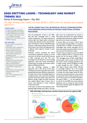
4 Fiber Laser Industrial Etching & Marking e-Book Compatible Materials Here is a list of the compatible materials that we have found work well with the fiber laser system: 17-4 PH stainless steel 303 stainless 4043 steel 6061 Aluminum ABS (black
