Transcription
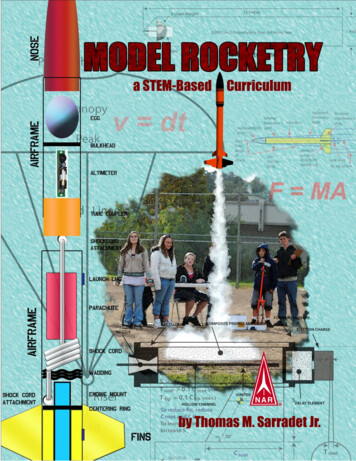
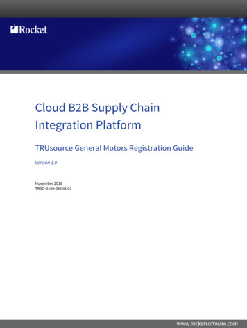
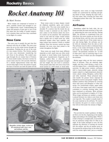
Rocketry BasicsRocket Anatomy 101By Mark Newtonnose cone.Most rockets are composed of sections orparts, carefully chosen and arranged to create a flight-worthy vessel. Understanding thename and purpose of each part is one of thefirst steps into the hobby of model rocketry.Let’s examine these and how they contributeto the flight of a rocket.Nose cones come in many shapes: rounded, elliptical, parabolic, ogive, and conical,to name a few. The nose cone usually has ashoulder Ñ a section that fits inside the airframe to keep it centered on the rocket Ñand a place on the bottom where the recovery system can be attached. This attachmentvaries in size with the rocket: model rocketshave a plastic slot or small screw eye, whilemid-sized rockets often have eyebolts, andlarge rockets have massive U-bolts or weldedeyebolts. Once the recovery system has beenattached, the nose cone stays joined to therocket throughout the flight.Nose ConeThe nose cone is usually the part that firstinteracts with the air in flight. The nose coneparts the air as the rocket moves through theatmosphere. Pushing the air out of the rocket’s way creates friction. The friction pushesthe nose cone downward, transferring theair’s force to the airframe. The rocket’s passage through the air creates heat of friction;for most model rockets, this heat is trivial, because it lasts only for a few seconds. However,for a slender high-powered rocket that fliesseveral miles high at twice the speed of sound,the heat of friction can melt the paint off theNose cones are made from many differentmaterials as well: small ones are often molded plastic or wood (balsa wood, basswood);high power manufacturers frequently use fiberglass, carbon fiber, or other compositematerials. Composite provide greater strengthand less weight, but cost more to purchase.Some people make their own nose cones fromwood turned in a drill chuck or wood lathe.Frequently, nose cones on large home-builtrockets are constructed by stacking and gluing sheets of foam, shaping the stack with ahot wire cutter, then covering the foam witha fiberglass/carbon fiber skin. The variationsare endless.AirframeSometimes called the body tube, the airframe provides the main structure of the rocket, supporting the nose cone and fins. Duringflight, the airframe is compressed from twodirections: the motor pushes up from the bottom during thrust, and the nose cone pushesdown as it parts the air. If the rocket veers toone side during flight, the airframe can behit with air resistance from the side as well.The airframe must be able to withstand theseforces, or the rocket will buckle or break. Onthe inside, the airframe holds the recoverysystem -- the parachute, streamer, etc -- as wellas other parts, such as centering rings or motor tubes, some of which can also strengthenthe airframe.Rolled paper tubes are the most commonform of airframe. They are relatively lightweight, and they crush during a crash to absorb the impact force -- a desirable safety characteristic. In high power rocketry, airframesshift to heavy-walled paper, phenolic tubing(paper soaked in a high-temperature phenolicresin), plastic tubing, fiberglass, carbon fiberand other materials. These advanced materials handle the greater forces imposed byhigh-thrust motors and greater weights. Somebuilders reinforce their airframes by coveringthem with epoxy and fiberglass or other materials. For scratch-built rockets, paper tubesof all sizes, from paper towel rolls to oatmealcontainers to concrete forming tubes, havebeen employed as airframes. Most airframetubes can be purchased in lengths of 2-5 feet.When longer airframes are needed, a coupleris placed between two tubes to join them intoone long tube. The coupler is usually made ofthe same material as the airframe. No matterthe material, the goal is to create a structurethat will not fold under the stresses of flight.FinsRegardless of their shape, rockets areall constructed with a nose cone,and airframe and fins.4Fins provide the rocket’s guidance. In flight,air flows over the fins, beginning at the leadingedges and ending at the trailing edges. When arocket is flying in a straight path, it encountersless air resistance (drag) than if it flies at anangle. If the rocket attempts to turn, the finsopposite the direction of turning are movedinto the airflow, and the air pushes more onthe exposed fin surfaces than on the other fins,until the rocket rights itself, just as a weatherNAR MEMBER GUIDEBOOK, January 2012 Edition
Rocketry Basicsvane always points into the wind. Fins areusually the first part of a rocket to fail duringpowered flight, because they have air flowingaround them on every side, and they are madeof thin material to reduce their air resistanceand weight. Fins can fail because they literallyflutter apart, or can simply separate from therocket because they are not properly attached.In either case, failure of one fin usually doomsthe flight, as its guidance system is now unbalanced, and there is less air resistance near thetail once the fin is gone, moving the center ofpressure (CP) forward, perhaps even ahead ofthe center of gravity (CG). At this point, therocket often does a few quick loops to celebrate the loss, likely tearing the airframe apartin the process.Because thin fins have less air resistancethan thick ones, rigid materials are used toprovide stiffness with minimum thickness. Formodel rockets, balsa wood or basswood are favorites. Competition models may use waferglass, a thin material made from plastics andfiberglass called G-10 (garolite). High powerrockets use aircraft-grade birch plywood orthicker sheets of G-10. These materials arestrong, but they become very heavy as theirsize and thickness increases. To reduce theweight of large fins, some builders use lightermaterials for the center (core) such as foamor balsa wood, add hardwood strips for the finedges, then reinforce the core with a skin ofthin hardwood or composites, such as fiberglass/epoxy. If built properly, these reinforcedfins can perform as well as solid fins, but witha fraction of the weight.Whatever material is chosen, the fins mustbe secured to the rocket at their root edges, sothey will not separate from the airframe during the most stressful part of the flight (usu-ally at motor burnout), sometimes at speedsbeyond 1000 miles per hour. Model rocket finsare usually just glued to the airframe surface,while high power rockets often have fins withtabs that fit through slots cut in the airframe;the tabs are glued tothe motor tube. Theseare known as throughthe-wall fins; they gainstrength by being gluedboth to the motor tubeand to the airframe.There are many othertechniques to strengthen fin attachment thatyou will find as youprogress in the hobby.No matter the technique, the goal is tokeep the fins attachedto the rocket throughout the flight.Motor TubeThe motor tube contains the motor and isattached to the airframe in some manner, usually with centering rings. The motor tube is often made of the same material as the airframe.A model-rocket motor tube often has a thrustring inside and the motor pushes against thering during thrust. High power rockets haveno thrust ring inside -- the thrust ring is at theaft end of the motor. This lets you insert motors of different lengths without spacers. Themotor tube transfers the thrust of the motorto the centering rings, which transfer it tothe airframe. Therefore, the motor tube andcentering rings must be able to withstand thehighest impulse produced by the motor. In addition, the motor tube must be able to handleNAR MEMBER GUIDEBOOK, January 2012 Editionthe heat produced by the motor, where surface temperatures can go beyond 200F.Centering RingsThe centering ringscenter the motor tubeinside the airframeand transfer the thrustof the motor to the airframe. Model-rocketcentering rings aremade of cardboardor balsa wood. Forhigh power rockets,aircraft-gradeplywood or G-10 is thematerial of choice. Arocket weighing up to3 pound would probably have 1/8"-thick plywood centering rings; a30-pound rocket might use 3/4" plywood. Justlike fins, centering rings get very heavy as theyget larger and thicker. As with fins, centeringrings can be made from lighter materials, reinforced with composites like epoxy/fiberglassto give the same strength as wood but withless weight.In larger rockets, it is common for the forward centering ring to do double duty: a Ubolt or forged eyebolt in the centering ringprovides a solid attachment point for the recovery system. Likewise, the aft centering ringoften holds the motor-retention hardware.Motor RetentionOnce a model-rocket motor’s propellant hasburned out, its delay charge gives the rockettime to coast to maximum altitude. Once this5
Rocketry Basicsniques, including parachute, streamer, glider,helicopter, featherweight, tumble, and noseblow for starters. The most common recovery method is the parachute or streamer formodel rockets, with parachutes being therule for high power rockets. Parachutes alsochange as rockets change, from inexpensiveplastic sheets in model rockets to the moreexpensive, bulkier, and heavier nylon fabricfor large rockets. Plastic parachutes, even wellconstructed ones, cannot handle the stressesimposed by large, heavy rockets. Streamerswork well for small rockets, but are not effective for safe recovery of heavy rockets.delay burns through, the charge pressurizesthe interior of the rocket, forcing it apart anddeploying the recovery system; however, whenthe interior is pressurized, the rocket motorwill be blown out the aft end of the rocketunless something restrains it. The motor-retention system secures the motor, so it cannot leave the motor tube in flight. An engineholder, a lightweight metal clip, is frequentlyused for small motors. The clip snaps overthe motor to restrain it, then the clip can bepulled back to release the burned-out motor.This style of clip is found in most kits in thehobby shop.Such a clip is inadequate for high powerrocket motors: most large rocket kits do notinclude motor retention, allowing the builder to choose a suitable method. As a result,other retention devices have been developedfor larger motors. A common homemade design is the “Kaplow clip”, in which a bolt isthreaded into a blind T-nut set in the centering ring. The bolt and T-nut secure a metaltab that hooks over the aft ring of the motor.Several commercial retainers are available,including variations of the Kaplow clip (e.g.PML), retainers with snap rings (e.g. GiantLeap Rocketry) and threaded retainers (e.g.Aeropack). All these devices have differentbenefits and costs, but all accomplish the primary job: keep the motor in the rocket.Recovery SystemThe recovery system consists of severalparts that work together to reduce the airspeed of the rocket, so it can be recovered andflown again. The NAR safety code requires every rocket to have a recovery system. A typicalrecovery system consists of shock-cord attachment point(s), a length of shock cord, flameprotection, and the recovery device itself,which is usually a parachute.6If everything goes perfectly, the recoverysystem is deployed precisely at apogee, thepeak of flight, when the rocket is moving veryslowly. Things do not always happen perfectly. If the recovery system is deployed a fewseconds before (or after) apogee, the rocketmay be moving upward (or downward) athigh speed. Ejecting a parachute, while moving at 300 feet per second(fps), puts a greatstrain on the chute, the shock cord, the attachment points, and the airframe itself. Recoverysystems must be able to handle forces 40-60times the rocket’s total weight. Model rockets are relatively lightweight, so a folded-overpiece of paper, glued to the shock cord and tothe inside of the airframe, is adequate. Somemodels use a piece of Kevlar around the motor tube for the attachment point.However, the attachment point must bemuch stronger for bigger, heavier rockets.Large rockets use one or more U-bolts orforged eyebolts through the centering ringsto absorb the large stresses of deploying therecovery system. Large rockets may also use aNomex deployment bag or some similar technique to delay the opening of the parachute.A delayed opening has advantages: when therocket deploys its recovery system, it separates into pieces connected by the shock cord,usually (a) the nose cone, (b) the chute, and(c) the airframe, motor, and fins. While theassembled rocket is highly streamlined, sothat it can move through the air with minimaldrag, its individual components are not. Oncethe nose cone and airframe separate, the increased drag will quickly slow down the rocket, even before the parachute opens. Delayingthe parachute opening for a second or two canmean the difference between opening at 300fps or 100 fps -- a large difference in stress onthe recovery system.Rockets can be recovered by many tech-Commercial motors typically use black powder (BP) to pressurize and separate the rocketfor recovery. BP burns at temperatures near2000F, which can destroy nylon or plastic. Toprotect heat-sensitive rocket parts, flameproofwadding is placed between the motor and therecovery system. As rockets get larger, thewadding may be replaced with a cloth madeof flameproof aramid fibers, such as Kevlar orNomex. Another approach is to cool ejectiongas before it contacts the sensitive parts, bymaking the gas pass through a series of offset baffles or a mass of heat-resistant materialsuch as coarse stainless steel wool.Launch Lug/RailButtonsThe launch lug is a small but importantpart of the model rocket. The lug fits over thelaunch rod, so that the rocket is guided alongthe rod for the first few feet of flight, while it isstill moving too slowly to be stabilized by fins.The launch rod may be 1/8" in diameter forsmall model rockets, up to 1" for large rockets.It is important to select a rod that is properfor the weight and length of the rocket: a 1/8"rod works fine for small rockets, but it is inadequate for, say, a 1-pound rocket, where a 1/4"rod is a better choice. Most flyers use a rodbetween 3 and 6 feet long. One disadvantageof a launch rod is “rod whip”: as the rocketleaves, the rod whips, sometimes throwing therocket off its flight path.Since rails are stiffer than rods, they are agood choice for high power rockets. Rail buttons or guides are then used on the rocket instead of lugs. Seen from the top, a rail appearslike the letter C. The button or guide slidesdown the gap in the rail. The rocket moves upthe gap during flight. A rail can be reinforcedwith guy wires, and it can handle large rockets without rod whip. In spite of the greatercost of rails, they are increasing in popularity. Launch buttons and rail guides differ onlyslightly: a button looks like a miniature sewingspool, while a guide is a longer piece with aslot on each side, to fit down the rail.NAR MEMBER GUIDEBOOK, January 2012 Edition
Rocketry BasicsBuilding a RocketBy Mark Newtontwo items made from different materials.Yes, it is the always the first rule in construction: read and follow the directions. But nowyou want to build a rocket using your ownparts, or you want to modify a manufacturer’skit for more radical flights. What can you doto keep it together with that F motor, whenthe kit was really designed for a D motor?Simple: use your bag of building tricks to reinforce key parts of the rocket so it can “returnalive” from that flight you’ve planned.NOTE: You will become hypersensitive (allergic) to epoxy over time if you work with itwithout wearing protective equipment such asnitrile gloves. Latex gloves do not protect youfrom epoxy. Also, use epoxy cement only inareas with good ventilation.The FundamentalRule of BuildingNow, having talked up epoxy for most materials, let’s look at the exceptions. When building many of the new ready-to-fly kits, you canuse modeling cement to bond plastic to plastic. Also, most epoxies do not hold up underhigh temperatures. For bonding metal motortempt to shred fins from the airframe. The finsusually also receive a beating when the rockethits the ground. Reinforcement and buildingtechniques can increase the strength of fins.Let’s discuss some techniques for wringingmore performance from your fins:Reinforce your fin stock. Balsa or plywoodfins can be reinforced with a layer of typingpaper. Coat the fins on both sides with a thincoat of yellow glue, cover each side with typing paper, then put a layer of wax paper overthe typing paper. Press the whole setup under books, bricks, or something else flat andheavy for several hours while the glue dries.After the glue has dried, remove the fins, peeloff the wax paper, and carefully coat the typing paper with CA. The CA will stiffen the paper and wood so that it sands easily. From thisAll right, maybe there are more rules thanone to remember. But over time this rulekeeps moving to the top of the list: MOREATTACHMENT SURFACE AREA IS BETTER. You will notice how much the surfacearea impacts the various components whenthe rocket is assembled, for example, sanding a surface before gluing cuts micro-ridgesin the surface. These ridges provide more surface area for the glue to bond to, increasingthe strength of the bond. You will build stronger rockets if you do things to increase surfacearea as you build.Choose YourAdhesive WiselyRocket parts come in a variety of materials: molded plastic, paper, cardboard, plywood, balsa wood/basswood, phenolic tubing,Quantum tubing, fiberglass, and aluminumare some of the materials in your rocket. Nosingle glue has the ideal properties to bondall these materials together. To achieve thegreatest strength with the least weight, youmust choose adhesives with the best properties for the materials you want to bond. Forexample, two-part epoxy gives a strong bondto hold wood fins on a paper body tube, butit adds more weight to the rocket than yellow(aliphatic) glue does. For bonding paper andwood products together, yellow glue is yourbest choice. It is stronger than the materialsyou will bond. Once glued, the parts will stripaway from the glue before the glue itself fails,and yellow glue is much easier to handle thanepoxy: no mixing, no gloves, less expense, andwater clean-up. Outside of wood and paper,most other materials adhere best with epoxy,including phenolic tubes, G-10 fins, Quantumtubing, plastic nose cones, and aluminum.Epoxy is the rocketeer’s friend when bondingmounts or retainers to motor tubes, specialhigh-temperature epoxies are recommended.For field repairs, nothing beats cyanoacrylate (CA), also known as “super glue.” It willrepair broken fins and launch lugs. It is wonderful stuff to have in your field box. CA alsohas another feature: when soaked into paperor wood, it acts like an instant sealer, makingthe fibers stiff. CA-soaked items sand easily,without the “fuzz” that normally accompaniessanded wood or paper. You have to pick theright CA for the job, as it comes in thin, medium, and thick viscosities. Thin CA is bestfor soaking into wood/paper, while mediumor thick CA is best for bonding materialsin construction or field repair. Some rocketmanufacturers recommend CA for constructing their kits.FinsFor the typical rocket, fins and motor mountsare the parts that receive the most stress inflight. Motor thrust and wind shear both at-NAR MEMBER GUIDEBOOK, January 2012 Editionpoint, the fin can be sanded, cut, or treatedlike any other balsa fin. This technique alsoeliminates the need for sealing balsa fins priorto painting.Reinforce your fin joints. Increasing thesurface area of your fin joint will keep finsattached through those high-performanceflights, especially if your fins are attached directly to the airframe (surface mounted). Thesimplest reinforcement is a glue fillet, whichforms a smooth joint between airframe and finsurfaces. Proper fillet technique is discussedin most basic rocket kits. For more strength,use reinforcement materials. Tissue paper andyellow glue work great for model rockets. Cuta rectangle of tissue paper as long as the finjoint to be reinforced, and about two inchesin width. Cover the tissue with a thin coat ofyellow glue and gently push it into the jointa Popsicle stick helps. You can increase thestrength further with a second layer of tissue.After you’ve done several, you will be ableto create a smooth reinforcement that keeps7
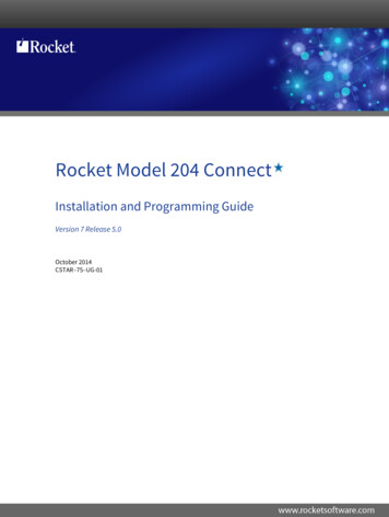
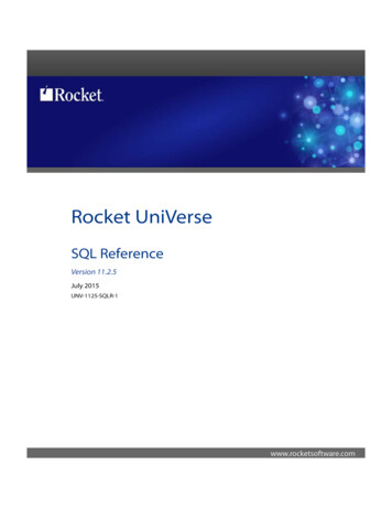
Rocketry Basicsthose fins attached. This technique also worksfor high-power rockets-substitute fiberglasscloth and epoxy as reinforcement materials.Motor MountTube with Frontand MiddleCentering RingsCutawayAirframe withMotor MountAssemblyCutawayAirframe withTTW Fins Gluedto MotorMount TubeUse through-the-wall (TTW) fins. Throughthe-wall fins have tabs that go through theairframe and bond directly to the motor tube.This requires fin slots to be cut through theairframe. TTW fins achieve greater strengthby providing multiple locations (that’s surfacearea) to bond the fins to the airframe and motor tube: fillets can be placed on the inside andoutside of the airframe and on the motor tube,especially if the aft centering ring is removedto permit access to the interior of the rocket.To get this access, slide in the motor mountand centering rings, but glue only the forwardcentering ring to the motor tube—do not putany glue on the aft centering ring. Once theforward ring has dried, carefully remove theaft ring, using a hobby knife. Once the aft ringis removed, you will have access to the TTWfins, and can now put glue fillets or reinforcements on every fin/airframe joint. This makesan incredibly strong fin joint. Once all glue isset, the aft centering ring can be glued intoplace. Another way to create a TTW setupis to glue centering rings, fins, and recoveryattachment to the motor tube, then slide thewhole unit into the airframe. This is a greatway to build a strong structure, but requiresthe rocket’s fin slots to extend to the rear ofthe airframe.Your choice of technique may be limitedby your rocket choice: for example, a kit withsurface-mounted fins will eliminate the TTWtechnique, but you could reinforce the fin andthe fin joint. In addition, these techniques canbe combined: paper-reinforced balsa fins canbe designed for through-the-wall mounting,with tissue paper reinforcements at the joint.Airframe and CouplerTTW FinsFilleted toAirframe withAft CenteringRing8It is pretty rare to have a rocket fail in flightdue to collapse of the airframe if the airframeis commercially available tubing intended forthe size motor used. Your chance of failure becomes greater with long, slender rockets suchas SuperRoc competition models. To strengthen airframes, two general techniques are reinforcement with composite materials like fiberglass (or carbon fiber) and epoxy, or using asmaller tube inside the airframe-a “tube in atube” design. The tube in a tube is a simpletechnique to add considerable strength to theairframe. A set of centering rings keeps the inner tube correctly located inside the airframe.This technique can be even more effectivewhen two-part foam is poured between the twotubes and permitted to harden. Another variation is a ring of wooden strips glued aroundthe inside (or outside) of a tube. You haveto be careful about wood choice here: staywith lightweight woods like balsa, basswood,or spruce. Consider a combination: a tubewithin a tube, centered with a series of balsawood strips. This can turn a model rocket airframe into a mid-power (or even high power)airframe. If you have enough couplers, gluingthem inside the airframe is a simple way todouble the airframe’s thickness.One more trick: the ends of a body tube canbe hardened by adding a few drops of thin cyanoacrylate (CA) and giving it several minutesto cure. Once cured, the hardened ends canbe sanded to a smooth finish-a great way topermit nose cones and transitions to slide easily on/off the tubing. Do this in a well-ventilated area because of the strong CA fumes.When a long rocket has an airframe failure,it almost always occurs at a coupler joint. Asa rule, couplers are made to be the same thickness as the airframe tubing. If your coupler appears to be thin, you might want to strengthenit. Think of a coupler as an airframe, and usethe same techniques to stiffen the inner wallof the coupler.Nose ConeReally, there is not much you should do toincrease the performance of your nose cone.One area that you can improve is the attachment point of the nose cone to the recoverysystem. Some nose cones provide no attachment point, and some provide a point that isprobably too weak. In general, you want anattachment point that is able to handle loadsthat are fifty times the weight of the nosecone. For example, a 6-ounce nose cone needsan attachment point that can handle loads of6 ounces x 50 300 ounces.There are several ways to get this type of attachment point. Some nose cones have a spotin their base to permit a quarter-inch eye to bescrewed into the base. If an eye is used, alwaystry to use one that does not have any breakwhere the circle closes. Solid eyes, whetherwelded, cast, or forged, can handle 2–3 timesthe working load of an open eye, and will notopen up under high loads. If your nose conehas no attachment point, then create one: invert the nose cone and pour a small amountof epoxy into the nose tip. Use a stick to pusha piece of tubular nylon or Kevlar string intothe epoxy, and permit it to cure. Anothersimple attachment point can be made by placing a piece of Kevlar or tubular nylon undera small square of fiberglass, saturated withepoxy glue. Press the square inside the nosecone, and permit it to cure. The larger the fiberglass square, the less likely that it will bepulled from the nose cone.If your nose cone is made of balsa wood, youcan seal the nose cone and give it a hard shellNAR MEMBER GUIDEBOOK, January 2012 Edition
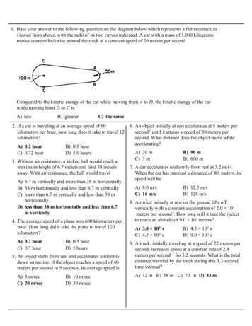
Rocketry Basicsby dripping thin cyanoacrylate (CA) over thenose cone. This will harden the wood’s fibers, making it easy to sand. Next, fill in deepgroves with Elmer’s Fill-N-Finish Lite, sandagain, and you’re ready for final finishing.Photo courtesy ofwww.apogeerockets.comLaunch Lugs/Rail ButtonsAmong fliers of mid and high-power rockets,there is a move away from launch lugs towardrail buttons/guides. Rails are more rigid thanrods, making them a better choice for thoselong and heavy rockets. Whether you uselaunch lugs or rail buttons, the biggest concern is always getting a good attachment tothe airframe. For launch lugs, it is easier touse paper launch lugs on paper airframes, andbrass or aluminum lugs on phenolic, fiberglass,or Quantum tubing. Paper lugs on paper airframes bond firmly if both surfaces are sanded before applying yellow glue. A little morework is required for brass or aluminum launchlugs, as they have a much smoother surface.To prepare metallic lugs, first sand the lug andthe airframe with extra-fine sandpaper to increase the bonding surface, then clean bothsurfaces thoroughly (alcohol is recommendedas a cleaning solvent). The surfaces can thenbe bonded with epoxy or, for more strength,cover the lug with a piece of epoxy-soaked fiberglass, extending over onto the body tube aninch on each side. This increases the bondedsurface area, decreasing the chance that thelug will pull off during flight.Rail buttons and rail guides vary. Some railguides are designed for a surface mount, usingan adhesive strip. These are simple to attach,but great care has to be given to assure a goodfit to the airframe and a clean surface for theadhesive. Before applying the adhesive, lay apiece of sandpaper, rough side up, on the airframe. Slide the rail guide back and forth onthe sandpaper, keeping it firmly against theairframe. This sanding will gradually makethe base of the guide conform to the curvatureof the airframe. Once the sanding is complete,sand the area on the airframe, clean bothsurfaces, place the adhesive strip on the railguide, and place the guide on the airframe.It is important that these surface-mountedrails be kept under pressure for several hours.Pressure can be applied with clamps (spring,rope, woodworking clamps, etc.). Traditional rail buttons are not surface mounted-theymust be attached through the airframe, andideally, also through a small piece of woodenreinforcement inside the airframe. An extrapiece of wood adds significant strength to thebutton. It’s a good thing. Retrofitting rail buttons to an existing rocket is more problematic, since you cannot get inside the rocket toget a good attachment point for each button.In this case, think about hanging a picture athome: use drywall anchors. Find a screw thatfits the rail button, and buy the matching plastic expansion piece. Drill the hole, insert theplastic expansion piece, then screw the buttondown on the airframe. This trick also workswell for retrofitting motor-retention tabs.some questions, you will be ready to makeyour own system. For a time-tested design,look at “Kaplow clip” below. There are dozens of designs that all function well. Attend aclub launch and just look around-you’ll see foryourself. A personal favorite is a piece of quarter-inch all-thread, attached to the side of themotor tube with a wrap or two of glue-soakedpaper and positioned so the threads protrudeabout half an inch beyond the aft end of themotor tube. On the field, slide in your motor,place a washer and quarter-inch nut on the allthread, and snug it down: simple, cheap, andeffective.Photo courtesy of www.aeropack.netMotor RetentionNothing ruins your day like losing your hundred-dollar reload case and driving your beautiful rocket into the earth because the recoverysystem did not deploy because the motor casing was ejected. It’s almost enough to makeyou want to go back to the office-almost. Thisneed not happen to you. A little time and effort spent on motor retention will pay rewardsin recovering your rocket to fly again. Mostmodel-rocket kits provide motor retention inthe form of a clip, but as you move into largerrockets, you are le
Sometimes called the body tube, the air-frame provides the main structure of the rock-et,ting suppor the nose cone and fins. During flight, the airframe is compressed from two directions: the motor pushes up from the bot-tom during thrust, and the nose con