Transcription
December 2-5, 2003 MGM Grand Hotel Las VegasUndocumented Autodesk ArchitecturalDesktop Tips and TricksT.J. MeehanBD42-1 This class is for Autodesk Architectural Desktop users of all abilities. We'll review 25-plus tips and tricksthat you won't find in the Help menu or manuals. These techniques have been compiled from actualusers who rely on the product every day to efficiently create accurate construction documentsAbout the Speaker:T.J. has worked for several years in architectural firms doing design and production work as well as CAD management.He is a certified instructor in AutoCAD and Autodesk Architectural Desktop as well as fluent in many office, graphics,and desktop publishing applications He is a dynamic figure, often seen scaling walls and crushing ice. He has beenknown to remodel train stations on his lunch break. He has translated ancient Sanskrit, written award-winning operas,and can manage time efficiently. He can pilot bicycles up severe inclines with unflagging speed and cook Thirty-MinuteBrownies in only twenty minutes. He is an expert in stucco, a veteran in love, and an outlaw in Peru. He playsbluegrass cello, was scouted by the Mets, and is the subject of numerous documentaries. Children trust him and thelaws of physics do not apply to him. He balances, he weaves, he dodges, and all his bills are paid. He has playedHamlet at the Kennedy Center, performed open-heart surgery, and spoken with Elvis He also writes AutoLISP andHTML code. T.J. has a degree in Architecture and is now completing his exams for his license.tjm@caddmicro.com
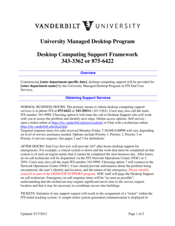
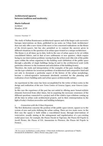
Undocumented Autodesk Architectural Desktop Tips and TricksTip 1Create a Standard Priority ListCreate a Wall Component Priority list with standardvalues to use for all your wall styles. The list couldbe based primarily on materials and broken down bystatus (see table). This is usually better for basebuildings.Or, it could be based primarily on status (new vs.demo vs. existing). This is usually better forinteriors.The priorities for the wall styles included withArchitectural Desktop are primarily material based.You can download a spreadsheet with their values aswell as examples of the others above MUFramingUse Zero Width ComponentsCreate a “Hatch Line” componentlocated in the center of the wall (EdgeOffset value) with either a zero or nextto zero width.Then, in the Display Properties for thatwall, assign the Hatch Line a color thatplots thick (or place it on a layer thatdoes the same) and give it a 321320120220Metal Stud21121221Wood Stud23123223Exterior 35135235EIFS / Stucco37137237Siding39139239Interior e45145245Paneling47147247Gypsum Board4914924950150250InsulationTip 2STATUSBatt51151251Rigid53153253
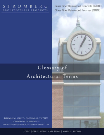
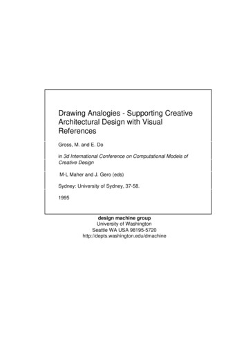
Undocumented Autodesk Architectural Desktop Tips and TricksTip 3Design a Batt Insulation Wall ComponentUsing the previous tip as an example,assign the Hatch Line component theBATTING linetype.Then, change the “Lt Scale” to anappropriate value based on wall widthand scale (the example shows 0.1250,which works well based on a 5 1/2” wallat 1/8” 1’-0” scale)Tip 4Use Different Components for Plan View vs. Model ViewThis allow you to use more symboliccomponents for the plan view (i.e. anexaggerated 2” backsplash whichreads better at 1/8” scale) versusmore realistic components for modelview (which is better for rendering)The example is for a wall stylerepresenting casework with differentcomponents for 2D and 3D. The 3Dcomponents are turned off in 2D(Plan) view through the DisplayProperties, while the 2D componentsare turned off in 3D (Model) view.Tip 5Create Place Holder Components Just for Sweep ProfilesCreate a wall component that has nowidth to be used as a placeholder for asweeping profile.Examples: Countertop nosing Baseboards, chair rails (wainscot), and crown molding Brick or stone ledges (drip caps)3
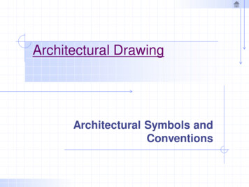
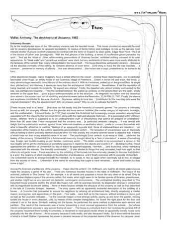
Undocumented Autodesk Architectural Desktop Tips and TricksTip 6Use “Add Selected” Whenever PossibleBy using the “Add Selected ” feature (highlightand right-click), you can add new walls that areexactly the same.This could be used by having a Legend blockwhere users can highlight the different object typesbefore drawing them.Matches: AutoCAD Properties (layer, color, linetype, etc.) AEC Object Properties (style, dimensions, justification, etc.) Modifiers (sweep profiles, body modifiers, entity display overrides, etc.)Tip 7Use Mass Elements for Difficult Wall CleanupsPlace mass elements on a non-plotting layer, then use interference conditions with the “Shrink Wrap Plan Effect”set to either “Additive” or “Subtractive”.1) Difficult wall conditionTip 82) Add a Mass Element3) Subtractive Interference ConditionUse Body Modifiers to Create a BullnoseCreate a 3D Solid or Mass Element to use as with the Wall Body Modifier feature to create a bullnosed corner.You can create blocks for different corner angles and radii.1) Walls before42) Add a 3D Solid or Mass Element3) Subtractive Wall Body Modifierattached to both walls
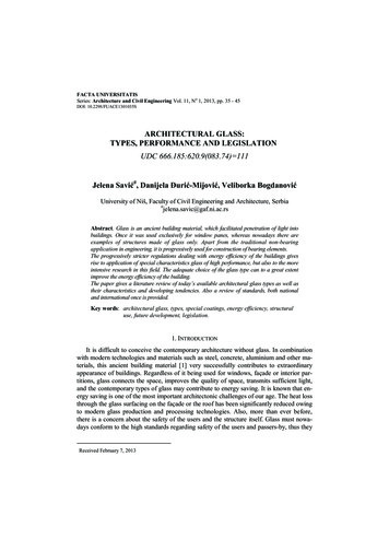
Undocumented Autodesk Architectural Desktop Tips and TricksTip 9Create Endcaps with an Open EndAny wall endcap created from a polyline with width will cause anopen end when used.This can be useful when you want to draw walls for a certainarea in a drawing and leave the rest as lines yet have themmatch up.Tip 10BeforeAfterBeforeAfterUse Wall Modifiers for Complex CleanupsWhen wall components change width, sometimes othercomponents don’t make the transition well.First, draw polylines the shape the component should be,making sure to give width to the segment that needs to connect(just like the previous tip). Then, convert those polylines intoplan modifiers in place.Tip 11Take Advantage of the NODE OSnapThe most effective way to get walls to cleanup correctly is to have their“grip lines” match up. Sometimes it is difficult to know where anotherwall’s grip line is located.Using the NODE Object Snap (OSnap) will allow you to snap directly tothe endpoint or midpoint of a wall’s grip line.Tip 12Use Layer Key Styles to Change the Status of ObjectsEven though AEC Objects (walls, doors, windows, etc.) are“keyed” to a particular layer upon insertion, they can also bere-keyed to a different layer afterwards. In other words,you can move an entire set of objects, without selectingthem individually, to different layers with one command.A good example of this would be to take an existing drawingand move part or all of the objects to their correspondingdemolition layers (i.e. doors would move from “A-Door” to“A-Door-Demo”).This can be achieved by using two different Layer Key Styles– one for your new work and one with the layers adding the“-Demo” or “-D” status field at the end of the layer name(and probably changing the color and linetype). Have thenew work Layer Key Style set current for most of yourdrawings, but when you’re ready to make a Demolition plan,set that Layer Key Style current. Then, use the “RemapObject Layers” command accessed from the “Format Layer Management” pulldown. Finally, select the objects tochange and use the “ByObject” option.5
Undocumented Autodesk Architectural Desktop Tips and TricksTip 13Work Between Different Floors in the Same DrawingWhen creating your Layer Standard, add a field at the beginningfor “Floor” – use values like “F03” for the third floor, “B01” forfirst basement level, “R02” for second floor roof, etc. Now, layernames will resemble “F02-Wall” for second floor walls and “M01Glaz” for mezzanine windows.You can then use Layer Filter Groups to manipulate all the layersfor a particular floor. Also, similar to the previous tip, you canutilize different Layer Key Styles for different floors, setting thecorrect one current depending on the floor you’re working on.Tip 14Change Insertion Points on Multi-View BlocksWhen inserting certain Multi-View Blocks from the DesignCenter, you can change theirinsertion points as you add them. Double-click on the block from the DesignCenter to bringup the “Add Multi-View Blocks” dialog. Then, tap the CTRL key to cycle through thedifferent insertion points.You can add extra insertion points to your own Multi-View blocks by creating POINT’s onthe DefPoints layer within one of the view blocks.Tip 15Don’t Use Solids for Multi-View BlocksACES Solids, a standard AutoCAD entity, are the preferred toolfor AutoCAD 3D modeling. But, there are better options touse when creating the 3D blocks for Multi-View Blocks.Instead use Mass Elements – they are easier to edit (sizes canbe easily adjusted with grips), have a much smaller file size,and allow the attachment of Materials through Mass ElementStyles.Tip 16Create Custom ComponentsIt is possible to add your own components to objects, such as hardware andpanels to a Door or a custom mullion profile to a Curtain Wall. Here are thesteps:1. Draw your custom component – use lines and polylines for 2D, Mass Elements for 3D2. Set all the properties (layer, color, linetype, etc.) to BYBLOCK3. Turn it into a standard AutoCAD block4. Go to the “Other” tab in the Object Display Properties of the object to change (modifyat the Style level or Object level, never at a Drawing Default level)5. Attach your custom component and change the setting for where it is inserted andhow it scales6. Modify its properties on the “Layer/Color/Linetype” tab6
Undocumented Autodesk Architectural Desktop Tips and TricksTip 17Have Those Custom Components Automatically ResizeWhen these custom blocks (from the previous tip) are sized to fit, ArchitecturalDesktop uses the overall extents of the block for sizing which can lead tounwanted results (see graphic).If POINT’s are added to the custom block on the DefPoints layer and placed in thecorrect positions, Architectural Desktop will scale the custom block using theoverall extents of those points, not of all the geometry.In this example, the points allow the custom door frame to wrap around the wall.Tip 18Center a Ceiling Grid in a RoomIf you already have a closedpolyline created to clip theceiling grid, you can centerthat ceiling grid within thepolyline using the followingsteps:Tip 191.2.3.4.Add a Ceiling Grid and size it one bay bigger than the closed polyline (i.e. the room)Choose “Select object ” from the “Boundary” property and select the polylinePick anywhere for the insertion pointWhen you are prompted for a rotation, slide your mouse (with ORTHO on) in thedirection of the desired rotation, then type “SN” at the command prompt.Create a “Background” Display ConfigurationDesign a Display Configuration that sets all object colors to one that plots out light (to use as backgrounds forengineers and consultants). The steps are as follows:1. Create a new Display Set called “Background” by copying your current Plan set2. Create a new Configuration and use the “Background” Display Set as default3. Go through each Object and anywhere a Display Representation is checked, right-click on it, select “Duplicate”, and usethat representation instead4. Set all the components in the Default Display Properties to reside on a “Background” layer with color and linetypeBYLAYERTip 20Organize Schedule DataWhen creating Properties in aProperty Set Definition, number theProperties so they are organizedbased on the order the data isdisplayed in the Schedule Table.Otherwise, they will be alphabetizedand users will have difficulty fillingout the fields.7
Undocumented Autodesk Architectural Desktop Tips and TricksTip 21Create Your Own Custom Tags for SchedulingFollow these steps to create your own custom tags for scheduling AEC Objects:Step 1 – Create a BlockCreate a standard AutoCAD block for the symbol you want (in this example, adoor tag). When naming the block, try to avoid using spaces, use underscoresinstead.When defining the attributes, set their height to 1 unit. This will allowArchitectural Desktop to automatically scale them.In order to have the attributes of the block automatically fill in schedule data(i.e. the door number), the tag of each attribute definition must be named in acertain way. The format is as follows (no spaces) Property Set Definition : Property(In this example, DOOR is the Property Set Definition and NUMBER is theproperty)Step 2 – Create a Multi-View BlockCreate a new Multi-View definition and name it, again using underscores insteadof spaces. From the “View Blocks” tab, highlight the “General” displayrepresentation in the left window. Click on the “Add ” button and a dialog boxwill display all the blocks in the drawing. Choose the block you created in Step 1and click “OK”. Finally, check only the appropriate view directions (probably just“Top” since it is a schedule tag).(If you are creating a tag for ceiling fixtures, choose the “Reflected” displayrepresentation instead of “General”)Step 3 – Export to the DesignCenterYou can export to the DesignCenter using the following Format AEC Content Wizard This will launch the “Create AEC Content Wizard” with a three step process. Thefirst dialog lets you choose which type of content to create. Choose “CustomCommand” and in the “Current Drawing” window, highlight both the block andthe MvBlock from the list, then click “Add ” to place them in the contentfile.In the “Command String” field, enter the following AecAnnoScheduleTagAdd PropertySetDefs.dwg SYMBOL CMI Door Tag LEADER noneThis command string is simply a script of an Architectural Desktop command with some options. After clicking “Next “, makesure to keep the “Attribute Text Style” set to “As Defined by Content”, the “Scale” set to “Annotation”, and choose anappropriate Layer Key (i.e. DOORNO for door tags). In the final dialog box simply add a “Detailed Description” and use the“Browse ” button to export your schedule tag to the appropriate folder.Tip 22Use Meaningful ColorsEveryone is accustomed to AutoCAD colors equat
T.J. has a degree in Architecture and is now completing his exams for his license. tjm@caddmicro.com . Undocumented Autodesk Architectural Desktop Tips and Tricks 2 Tip 1 Create a Standard Priority List Create a Wall Component Priority list with standard values to use for all your wall styles. The list could be based primarily on materials and broken down by status (see table). This is usually .