Transcription
DESIGNANDDETAILINGOF FLAT SLABESE SOEDARSONO HS27 FEBRUARY 2002
CONTENT IntroductionBenefitsDesign ConsiderationsDesign MethodologyAnalysis of Flat SlabDetailing
INTRODUCTIONWhat is a flat slab? a reinforced concrete slab supported directlyby concrete columns without the use ofbeams
INTRODUCTIONFlat slabFlat slab with column headFlat slab with drop panelsFlat slab with drop panel and column head
INTRODUCTIONUses of column heads : increase shear strength of slab reduce the moment in the slab by reducingthe clear or effective spanFlat slab with column head
INTRODUCTIONUses of drop panels : increase shear strength of slab increase negative moment capacity of slab stiffen the slab and hence reduce deflection
BENEFITS
BENEFITS Flexibility in room layoutSaving in building heightShorter construction timeEase of installation of M&E servicesPrefabricated welded meshBuildable score
Benefits . . .BenefitsFLEXIBILITY IN ROOM LAYOUT allows Architect to introduce partition walls anywhererequired allows owner to change the size of room layout allows choice of omitting false ceiling and finish soffitof slab with skim coating
Benefits . . .BenefitsSAVING IN BUILDING HEIGHT Lower storey height will reduce building weight due tolower partitions and cladding to façade approx. saves 10% in vertical members reduce foundation loadSlabSlabSlabSlabBea eam-Free
Benefits . . .BenefitsSHORTER CONSTRUCTION TIMEflat plate design willfacilitate the use ofbig table formwork toincrease productivity
Benefits . . .BenefitsSINGLE SOFFIT LEVEL2626Kitchen 3030 00KitchenLivingingLivRoo mmRooToilelett30 ard3030Single LevelCeilingFlat Plate Slab Simplified the table formwork needed
Benefits . . .BenefitsEASE OF INSTALLATIONOF M&E SERVICES all M & E services can be mounted directly on theunderside of the slab instead of bending them toavoid the beams avoids hacking through beams
Benefits . . .BenefitsPRE-FABRICATED WELDED MESH Prefabricated instandard sizes Minimisedinstallation time Better qualitycontrol
Benefits . . .BenefitsBUILDABLE SCORE allows standardized structural members andprefabricated sections to be integrated into thedesign for ease of construction this process will make the structure more buildable,reduce the number of site workers and increase theproductivity at site more tendency to achieve a higher Buildable score
DESIGNCONSIDERATIONS
Design Considerations.Considerations. . . .DesignWALL AND COLUMN POSITION Locate position of wall to maximise the structural stiffness forlateral loads Facilitates the rigidity to be located to the centre of buildingTypical floor plan of Compass the Elizabeth
Design Considerations.Considerations. . . .DesignOPTIMISATION OFSTRUCTURAL LAYOUT PLAN the sizes of vertical and structural structural memberscan be optimised to keep the volume of concrete forthe entire superstructure inclusive of walls and liftcores to be in the region of 0.4 to 0.5 m3 per squaremetre this figure is considered to be economical andcomparable to an optimum design in conventional ofbeam and slab systems
Design Considerations.Considerations. . . .DesignDEFLECTION CHECK necessary to include checking of the slab deflectionfor all load cases both for short and long term basis In general, under full service load, δ L/250 or 40mm whichever is smaller Limit set to prevent unsightly occurrence of cracks onnon-structural walls and floor finishes
Design Considerations.Considerations. . . .DesignCRACK CONTROL advisable to perform crack width calculations basedon spacing of reinforcement as detailed and themoment envelope obtained from structural analysis good detailing of reinforcement will– restrict the crack width to within acceptabletolerances as specified in the codes and– reduce future maintenance cost of the building
Design Considerations.Considerations. . . .DesignFLOOR OPENINGS No opening should encroach upon a column head or dropSufficient reinforcement must be provided to take care ofstress concentration
Design Considerations.Considerations. . . .DesignPUNCHING SHEAR always a critical consideration in flat plate designaround the columns instead of using thicker section, shear reinforcementin the form of shear heads, shear studs or stirrupcages may be embedded in the slab to enhanceshear capacity at the edges of walls and columns
Design Considerations.Considerations. . . .DesignPUNCHING SHEARShearStuds
Design Considerations.Considerations. . . .DesignCONSTRUCTION LOADS critical for fast track project where removal of forms atearly strength is required possible to achieve 70% of specified concrete cubestrength within a day or two by using high strengthconcrete alternatively use 2 sets of forms
Design Considerations.Considerations. . . .DesignLATERAL STABILITY buildings with flat plate design is generally less rigid lateral stiffness depends largely on the configurationof lift core position, layout of walls and columns frame action is normally insufficient to resist lateralloads in high rise buildings, it needs to act in tendamwith walls and lift cores to achieve the requiredstiffness
Design Considerations.Considerations. . . .DesignLATERAL STABILITYMULTIPLE FUNCTION PERIMETER BEAMS adds lateral rigidity reduce slab deflection
DESIGNMETHODOLOGY
Design methodologymethodology . .DesignMETHODS OF DESIGN the finite element analysis the simplified method the equivalent frame method
Design methodologymethodology . .DesignFINITE ELEMENT METHOD Based upon the division of complicated structures into smallerand simpler pieces (elements) whose behaviour can beformulated. E.g of software includes SAFE, ADAPT, etc results includes– moment and shear envelopes– contour of structural deformation
Structural AnalysisAnalysis . .Structural
Structural AnalysisAnalysis . .Structural
Structural AnalysisAnalysis . .Structural
Structural AnalysisAnalysis . .Structural
Structural AnalysisAnalysis . .Structural
Design methodologymethodology . .DesignSIMPLIFIED METHODTable 3.19 may be used provided Live load 1.25 Dead load Live load (excluding partitions) 5KN/m2 there are at least 3 rows of panels of approximatelyequal span in direction considered lateral stability is independent of slab columnconnections
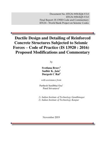
Design methodologymethodology . .DesignSIMPLIFIED METHODTable 3.19: BM and SF coefficients for flat slab or 3 or more equal spansOuter SupportNear centreof 1st spanFirst interiorspanCentre 2Fl* the design moments in the edge panel may have to be adjusted according to 3.7.4.3F is the total design ultimate load on the strip of slab between adjacent columns considered(1.4gk 1.6 qk)l is the effective span
Design methodologymethodology . .DesignEQUIVALENT FRAME METHOD most commonly used method the flat slab structure is divided longitudinally andtransversely into frames consisting of columnsand strips of slabs with :– stiffness of members based on concrete alone– for vertical loading, full width of the slab is used toevaluate stiffness– effect of drop panel may be neglected if dimension lx/3
Design methodologymethodology . .DesignEQUIVALENT FRAME METHODPlan of floor slabStep 1 : define line of supportin X & Y directions
Design methodologymethodology . .DesignEQUIVALENT FRAME METHOD910109.20.8DESIGN STRIP IN PROTOTYPE91010.610.5 0.8STRAIGHTENED DESIGN STRIPStep 2 : define design strips inX & Y directionsDESIGN STRIP IN ELEVATION
ANALYSIS OFFLAT SLAB
Analysis ofof flatflat slab.slab.AnalysisCOLUMN HEADEffective dimension of a head , lh (mm) lesser of lho or lh maxwhere lho actual dimension, lh max lc 2(dh-40)(i) lh lh, max(ii) lh lholh maxlh maxlholcdhlholcdh
Analysis ofof flatflat slab.slab.AnalysisCOLUMN HEAD(iv) lh lho(iii) lh lh, maxlh maxdh40lh maxlholholclcFor circular column or column head,effective diameter , hc 4 x area/ο 0.25 lxdh
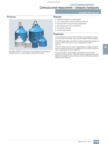
Analysis ofof flatflat slab.slab.AnalysisDIVISION OF PANELSThe panels are divided into ‘column strips’ and middle strips’in both direction.(a)Slab Without Dropslx/4Column striplx/4lx/4middlestriplx/4ly (longer span)lx (shorter span)Column stripmiddle strip (ly-lx/2)
Analysis ofof flatflat slab.slab.AnalysisSlab With DropsDropmiddle strip (ly-drop size)Droplx/4middlestriplx(b)Column strip drop sizely (longer span)note : ignore drop if dimension is less than lx/3
Analysis ofof flatflat slab.slab.AnalysisMOMENT DIVISIONApportionment between columnand middle strip expressed as %of the total negative designmoment Column stripMiddle stripNegative75%25%Positive55%45%Note : For slab with drops where the width of the middle stripexceeds L/2, the distribution of moment in the middle strip shouldbe increased in proportion to its increased width and the momentresisted by the column strip should be adjusted accordingly.
Analysis ofof flatflat slab.slab.AnalysisMOMENT DIVISION - EXAMPLE6000 6000 60006000600050007000Layout of building5000A floor slab in a building where stability is provided by shear wallsin one direction (N-S). The slab is without drops and is supportedinternally and on the external long sides by square columns . Theimposed loading on the floor is 5 KN/m2 and an allowance of2.5KN/m2 for finishes, etc. fcu 40 KN/m2, fy 460KN/m2
Analysis ofof flatflat slab.slab.AnalysisMOMENT DIVISION - 0400030003000150035002500Division of panels into strips in x and y direction
Analysis ofof flatflat slab.slab.AnalysisMOMENT DIVISION - EXAMPLE60006000200200353500250035200200369Column stripexterior support30003000centre of 1st span 0.75*35 on 2.5m strip 10.5Knm 0.55*200 on 2.5 strip 44KNm1st interior support 0.75*200 on 3m strip 50KNmcentre of interior span 0.55 *369 on 3m strip 67.7KNm35002500Middle stripexterior supportcentre of 1st span 0.25*35 on 2.5m strip 3.5KNm 0.45*200 on 2.5 strip 36KNm1st interior support 0.25*200 on 3m strip 16.7KNmcentre of interior span 0.45 *369 on 3m strip 55.4KNm
Analysis ofof flatflat slab.slab.AnalysisDESIGN FOR BENDINGINTERNAL PANELS columns and middle strips should be designed towithstand design moments from analysis
Analysis ofof flatflat slab.slab.AnalysisDESIGN FOR BENDINGEDGE PANELS apportionment of moment exactly the same as internalcolumns max. design moment transferable between slab andedge column by a column strip of breadth be isMt, max 0.15 be d2 fcu 0.5 design moment (EFM) 0.7 design moment (FEM)Otherwise structural arrangements shall be changed.
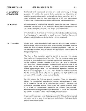
Analysis ofof flatflat slab.slab.AnalysisPUNCHING SHEARColumn perimeterPerimeter APerimeter B3d 3d4 2Column perimeter2. Determine vmax Veff /uod where uo isthe length of column perimeterCheck vma 0.8 f cu or 5 N/mm2Perimeter APerimeter BPerimeter C1. Calculate Veff kVt at columnperimeter (approx. equal span)Vt SF transferred from slabk 1.15 for internal column, 1.25corner columns and edge columnswhere M acts parallel to free edge and1.4 for edge columns where M acts atright angle to free edge3d 3d 3d4 4 23. Determine v (Veff -V/ud) where u isthe length of perimeter A and V is thecolumn load and check v vc) lx/34. Repeat step 3 for perimeter B and C
Analysis ofof flatflat slab.slab.AnalysisDEFLECTIONSpan/depth ratioCantilever7Simply supported20Continuous26(i) use normal span/effective depth ratio if drop width 1/3span each way; otherwise(ii) to apply0.9 modification factor for flat slab, orwhere drop panel width L/31.0 otherwise
Analysis ofof flatflat slab.slab.AnalysisOPENINGSHoles in areas bounded by the column strips may be formedproviding :greatest dimension 0.4 span length and total positive and negative moments are redistributed betweenthe remaining structure to meet the changed conditionslx (shorter span) ly (longer span)
Analysis ofof flatflat slab.slab.AnalysisOPENINGSHoles in areas common to two column strips may be formed providing :that their aggregate their length or width does not exceed one-tenth ofthe width of the column strip; that the reduced sections are capable of resisting with the moments;and that the perimeter for calculating the design shear stress is reduced ifappropriatelx (shorter span) ly (longer span)
Analysis ofof flatflat slab.slab.AnalysisOPENINGSHoles in areas common to the column strip and the middle strip maybe formed providing :that in aggregate their length or width does not exceed one-quarter ofthe width of the column strip and that the reduced sections are capable of resisting the design momentslx (shorter span) ly (longer span)
Analysis ofof flatflat slab.slab.AnalysisOPENINGSFor all other cases of openings, it should be framed onall sides with beams to carry the loads to the columns.
DETAILING OFFLAT SLAB
Detailing ofof flatflat slabslab . .DetailingTYPE OF REINFORCEMENTF-mesh- A mesh formed by main wire with cross wireat a fixed spacing of 800 mm#Main wire - hard drawn ribbed wire with diameter andspacing as per design#Cross wire - hard drawn smooth wire as holding wireH8-800mm c/c for main wire diameter 10mmH7-800mm c/c for main wire diameter of 10mmand below
Detailing ofof flatflat slabslab . .DetailingTYPE OF REINFORCEMENTF-Mesh 2Main WireHolding WireHolding Wire(800mm c/c)Main WireF-Mesh 1
Holding WireTensionLapMain Wire 45 dia.
HoldingWireMainWirePlan View of Mesh LayoutMainWire
F - MeshMain WireCross Wire
F - MeshMain WireCross Wire
Detailing ofof flatflat slabslab . .DetailingREINFORCEMENTFOR INTERNAL PANELS Reinforcement are arranged in 2 directions parallel toeach span; and 2/3 of the reinforcement required to resist negativemoment in the column strip must be placed in thecentre half of the strip for slab with drops, the top reinforcement should beplaced evenly across the column strip
STANDARD LAPPING OF MESH(FOR FLAT SLAB)
TYPICAL DETAIL SHOWING RECESS AT SLABSOFFIT FOR SERVICES
TYPICAL SECTION AT STAIRCASE
DETAILS OF INSPECTION CHAMBERAT APRON
DETAILS OF INSPECTION CHAMBER ATAPRON
DETAILS OF INSPECTION CHAMBER ATAPRON
DETAILS OF INSPECTION CHAMBER ATAPRON
DETAILS OF INSPECTION CHAMBER ATPLAY AREA
1ST STOREY (DWELLING UNIT) SLABDETAILS OF HOUSEHOLD SHELTER
TYPICAL DETAILS OF 125X250 RC CHANNELFOR GAS PIPE ENTRY
TYPICAL SECTIONTHRU’ COVERED HOUSEDRAIN (PRECAST)
First interior span Centre of interior span Interior span Moment -0.04Fl* 0.086Fl 0.083Fl*-0.063Fl 0.071Fl-0.055Fl Shear 0.45F 0.4F - 0.6F - 0.5F Total column moments 0.04Fl - - 0.022Fl - 0.022Fl * the design moments in the edge panel may have to be adjusted according to 3.7.4.3 F is the total desig