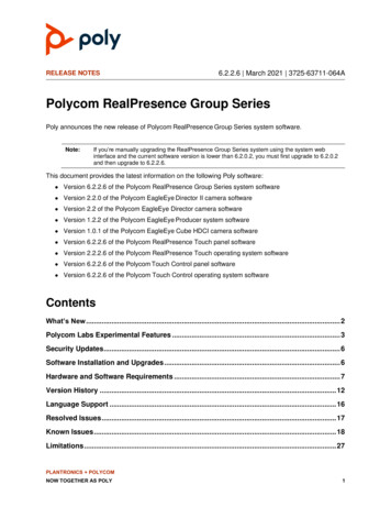
Transcription
TechnicalDocumentationMicrophone HandbookVol. 1: TheoryBrüel&KjærBKWORLD HEADQUARTERS: DK-2850 Nærum Denmark Telephone: 4542800500 Telex: 37316 bruka dk Fax: 4542801405 e-mail: info@bk.dk Internet: http://www.bk.dkBE 1447 –12
Microphone HandbookVolume 1March 2019Brüel & KjærMicrophone HandbookVol.1BE 1447 –12
Copyright 2019, Brüel & Kjær A/SAll rights reserved. No part of this publication may be reproduced or distributed in any formor by any means without prior consent in writing from Brüel & Kjær Sound & VibrationMeasurement A/S, Nærum, Denmark.0 0Microphone HandbookVol.1Brüel & Kjær
PrefaceThis volume provides background information on the Brüel & Kjær microphone productrange. It gives an insight into the theory behind the development of microphones and preamplifiers and explains the terminology used to describe these products.The aim of this volume is to promote a full understanding of measurement microphones andto provide sufficient background information for customers to get the best out of these products. It also gives adequate information for customers to be able to make informed andqualified decisions about the microphone products which are most suitable for their measurement requirements. These products are described in detail in more specific literature,such as Volume 2 of this handbook and in product data sheets.Chapter 1 gives a brief history of microphone development at Brüel & Kjær and provides aninsight into the research and development invested in microphone products. An overview ofthe production of microphones is also given.Chapter 2 gives a general introduction to microphone theory and explains the decisions thatare made about the design and construction of microphones.Chapter 3 provides more detailed information about the characteristics of microphones withthe aim of allowing an informed view on the specifications applied to microphone products.Chapter 4 introduces the main characteristics of preamplifiers and explains the categories ofinformation given in Volume 2.Chapter 5 provides information on the selection criteria commonly used to identify the mostsuitable microphone for different applications and also the most applicable accessories thatshould be used.Chapter 6 discusses the requirement for the calibration of microphones and offers an overview of calibration methods.BE 1447 –12Microphone HandbookVol.10 i
0 iiMicrophone HandbookVol.1Brüel & Kjær
Contents1. Introduction. 1 – 11.11.21.31.4Historical Background to Microphone Development at Brüel & Kjær . 1 – 2Development of Microphone Products. 1 – 5Production of Microphones at Brüel & Kjær . 1 – 9Product Support . 1 – 112. Microphone Theory . 2 – 12.12.22.32.42.5BE 1447 –12Sound Levels and Sound Fields. 2 – 2Sound Field Parameters. 2 – 2Sound Pressure and Pressure Level. 2 – 2Particle Velocity and Particle Velocity Level. 2 – 3Sound Intensity and Sound Intensity Level . 2 – 3Pressure-field. 2 – 4Free-field . 2 – 4Diffuse-field. 2 – 5Measurement Microphone Requirement. 2 – 5Measurement Microphone Design. 2 – 7Introduction . 2 – 7Design Description . 2 – 7Material and Process Requirements . 2 – 9Transduction Principles . 2 – 11Diaphragm and Air Stiffness . 2 – 15Static Pressure Equalization . 2 – 16Low Frequency Response and Vent Position . 2 – 17High Frequency Response. 2 – 20Microphone Sensitivity . 2 – 24Microphone Modelling by Equivalent Electric Circuits . 2 – 25Acoustic Impedance of Diaphragm System. 2 – 27Equivalent Volume of the Diaphragm System . 2 – 28Combination of Microphone and Preamplifier. 2 – 31Microphone Capacitance . 2 – 31Electrical Frequency Response of Microphone and Preamplifier . 2 – 32Inherent Noise of Microphone Systems. 2 – 35Distortion . 2 – 39Microphone Types Dedicated to Different Sound Fields. 2 – 43Influence of the Microphone on the Pressure-Field. 2 – 43Microphone HandbookVol.10 1
Contents2.62.72.8Pressure Field Microphone and Sensitivity .Influence of Microphone on the Measured Sound Pressure in a Free-Field .Free-Field Microphone and Sensitivity.Influence of the Microphone on the Measured Sound Pressure in aDiffuse Field .Diffuse Field Microphone and Sensitivity.Long Term Microphone Stability .Electrostatic Actuator Calibration .Introduction .Electrostatic Actuator .Electrostatic Calibration Pressure .Electrostatic Actuator Operation .Actuator and Pressure-field Responses.General Note on Actuator Calibration .Conclusion .2 – 452 – 452 – 482 – 492 – 502 – 512 – 542 – 542 – 552 – 552 – 572 – 582 – 582 – 593. Characteristics of Microphones . 3 – 13.13.23.33.43.53.63.73.83.93.103.113.120 2Introduction to Characteristics . 3 – 2The Calibration Chart and Diskette . 3 – 2Sensitivity. 3 – 3Open-circuit Sensitivity (So) . 3 – 3Loaded Sensitivity (Sc) . 3 – 4Correction-factors K and Ko . 3 – 5Frequency Response. 3 – 5Introduction and Optimised response . 3 – 5Low Frequency Response. 3 – 6High Frequency Response. 3 – 7Electrostatic Actuator Response. 3 – 7Free-field Response . 3 – 9Random Incidence Response. 3 – 9Pressure-field Response . 3 – 9Directional Characteristics. 3 – 10Dynamic Range . 3 – 11Inherent Noise . 3 – 11Maximum Sound Pressure Level. 3 – 12Equivalent Diaphragm Volume. 3 – 13Calibrator Load Volume . 3 – 13Capacitance . 3 – 13Polarisation Voltage . 3 – 14Externally Polarized Microphones . 3 – 14Prepolarized Microphones. 3 – 15Leakage Resistance . 3 – 16Stability . 3 – 17Irreversible Changes. 3 – 17Long-term stability. 3 – 17Handling . 3 – 17Short-term Stability . 3 – 17Microphone HandbookVol.1Brüel & Kjær
Contents3.13Reversible Changes .Effect of Temperature .Effect of Ambient Pressure .Effect of Humidity .Effect of Vibration .Effect of Magnetic Field .Electromagnetic Compatibility .3 – 183 – 183 – 193 – 213 – 213 – 213 – 214. Characteristics of Preamplifiers. 4 – 14.14.24.34.44.54.64.74.8Introduction to Characteristics of Preamplifiers. 4 – 2Definition of a Microphone Preamplifier. 4 – 2Selection of a Microphone Preamplifier . 4 – 2Contents of this Chapter . 4 – 2Frequency Response. 4 – 2Low Frequency Response . 4 – 2High Frequency Response. 4 – 3Dynamic Range . 4 – 5Upper limit of Dynamic Range . 4 – 5Maximum Voltage . 4 – 6Maximum Current. 4 – 6Maximum Slew Rate . 4 – 7Lower Limit of Dynamic Range . 4 – 8Phase Response . 4 – 11Effect of Temperature . 4 – 11Effect of Magnetic Fields . 4 – 13Electromagnetic Compatibility. 4 – 13The European EMC Directive. 4 – 13The CE label . 4 – 13EMC Test Facilities at Brüel & Kjær. 4 – 14Monitoring and Calibration Techniques . 4 – 15Insert Voltage Calibration . 4 – 16Charge Injection Calibration . 4 – 17CIC Input Signal Requirements . 4 – 195. Selecting a Microphone . 5 – 15.15.2BE 1447 –12Guidelines on Selecting Microphones .What to Consider.Frequency Response .Type of Sound Field .Limits of Dynamic Range.Microphone Venting .Phase Response .Polarisation.Standards Compliance .Environment .Microphone ��55–65–70 3
Contents5.3Microphone Array Applications. 5 – 8Selecting The Right Accessories . 5 – 8Low Wind Speed, Random Direction. 5 – 9High Wind Speed, Known Direction . 5 – 9Turbulent Pressure Fluctuations . 5 – 10Humidity. 5 – 106. Calibration . 6 – 16.16.26.36.46.56.6Introduction . 6 – 2Calibration of Microphones. 6 – 4Field Calibration . 6 – 4Laboratory Calibration . 6 – 5Primary Calibration Laboratories . 6 – 6Accredited Calibration Laboratories . 6 – 6Calibration at the Brüel & Kjær Factory. 6 – 7Calibration Hierarchy, Traceability and Uncertainty . 6 – 8Calibration Methods . 6 – 9Reciprocity Calibration Method. 6 – 10Substitution method. 6 – 11Comparison Method . 6 – 11Sound Pressure Calibrator Method. 6 – 12Actuator method. 6 – 12Insert Voltage Calibration Method . 6 – 13Charge Injection Calibration Method . 6 – 14Index0 4Microphone HandbookVol.1Brüel & Kjær
Chapter 1IntroductionBE 1447 –12Microphone HandbookVol.11 1
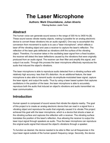
Chapter 1 — IntroductionHistorical Background to Microphone Development at Brüel & Kjær1.1Historical Background to Microphone Development atBrüel & KjærBrüel & Kjær began producing microphones in 1945. By the late 1950s they wereestablished as a leading supplier of measurement microphones, due largely to theinspirational leadership and enthusiasm of Dr. P.V. Brüel in the field of microphonedevelopment. In parallel, Brüel & Kjær also conceived, designed and developed complete acoustic measurement systems. Measurement microphones formed an important part of these systems, in combination with instruments such as analysers,recorders and sound level meters.From this beginning, Brüel & Kjær gained an increasingly good reputation amongstusers of microphones, both in the acoustics industry and in the field of academicresearch. This was achieved as a result of providing a high standard of service andreliable, well built products. The product range was also enhanced by a programmeof research and development that ensured continuous improvements in the accuracyand performance of new instruments. Today, this approach continues to deliver innovative measurement instrumentation, including a comprehensive range of measurement microphones in sizes from 1/8″ to 1″. Together these microphones cover allaspects of measurement microphone usage.Fig.1.1Range of condenser measurement microphonesBy the early 1970s, Brüel & Kjær’s strong presence in the measurement microphonefield had become firmly established with the development of high sensitivity 1/2″microphones. These microphones benefited from new techniques allowing less tension in the diaphragm, leading to an increase in sensitivity of approximately 12 dB.During this period Brüel & Kjær also improved techniques to accurately measureand document the performance parameters of their measurement microphones andsupplied this information in the form of calibration charts. Microphones could subsequently be relied upon according to certain stated parameters.1 2Microphone HandbookVol.1Brüel & Kjær
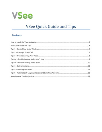
Chapter 1 — IntroductionHistorical Background to Microphone Development at Brüel & KjærCalibration equipment was also made, such as reciprocity equipment for laboratorycalibration and the pioneering hand-held pistonphone. This convenient calibrationdevice effectively improved the accuracy of everyday microphone usage by allowingusers to check measurement accuracy in the field.In 1973 Brüel & Kjær consolidated their position as the leading microphone producer by meeting a request from Western Electric to supply 1″ microphones to replacetheir successful but ageing WE 640AA microphone. The Brüel & Kjær solution tookthe form of the classic Type 4160 microphone. The 4160 together with the 4180 (the1/2″ version) were quickly established as reference microphones for laboratory standard use, due mainly to their stability and accurately documented performance parameters.Fig.1.2Microphone Types 4180 1/2″ and 4160 1″ are used byDPLA as highly stable reference microphones for laboratory calibrationsFurther innovations ensued, notably in improvements to electret processes duringthe 1970s, resulting in the production of stable prepolarised microphones whichbecame standard for use with sound level meters. The 1980s brought further developments, in particular in the field of sound intensity measurement. The mid 1980salso saw the development of specialised types of probe microphone. This microphonemade use of a revolutionary and now patented tube system which gives a flatBE 1447 –12Microphone HandbookVol.11 3
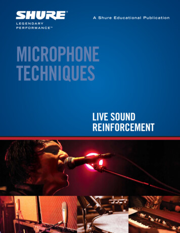
Chapter 1 — IntroductionHistorical Background to Microphone Development at Brüel & Kjærfrequency response and allows for measurements in places where access for standard measurement microphones is difficult.Improvements have continued into the 1990s with the introduction of highly accurate yet robust microphones (the Falcon RangeTM) and a microphone unit speciallydesigned for permanent outdoor use. These microphones have proven their ability toperform effectively in harsh measurement environments.Throughout the history of Brüel & Kjær, a collaborative approach with customershas led to improvements in the design, performance and reliability of measurementmicrophones. In addition, Brüel & Kjær’s response to customer requirements hascreated several innovations in the related acoustic measurement field, including:— Sound intensity microphones, phase-matched for accurate, low frequency measurements see Section 2.3.7.— Sound intensity calibrator, simulating a free-field environment for calibration ofsound intensity equipment.— Charge injection calibration (patented) for verification of complete measurementsystems see, Section 4.8.— Feedback calibration (Multitone calibrator) allowing calibration of microphones,up to 16 kHz.— New intensity measurement microphones with patented pressure equalisationvent system giving much improved low frequency response.Fig.1.31 4Sound Intensity probe using a phase-matched pair of microphonesMicrophone HandbookVol.1Brüel & Kjær
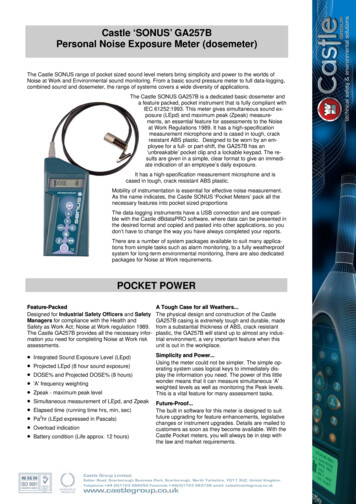
Chapter 1 — IntroductionDevelopment of Microphone ProductsThese and other innovations reflect a dedicated and uncompromising approach tothe creation of measurement microphones, where reliability, accuracy and qualityare the key considerations. This philosophy continues to find ways of meeting theneeds of a growing global market through intensive research and developmentwork.1.2Development of Microphone ProductsDevelopment of microphone products is performed by a dedicated team of engineers.This is something which is not easy to provide given the relatively small and specialist market for precision microphone products. However, at Brüel & Kjær this investment is seen as essential because it allows the design parameters and physicalproperties of microphones to be based on a solid foundation of knowledge, skills andexperience.As a result of its pioneering nature, development work often enjoys a symbioticrelationship with standards organisations. New product developments contributenew standards to the research and development field, while Brüel & Kjær productsbenefit from a free-flow of information on the most current and industry-wide requirements for microphones. Improved standards and more advanced Brüel & Kjærproducts result.Similarly, this collaborative approach to development includes work with universities and knowledge centres with benefits to both sides. A good example of thisapproach is the cooperation between Brüel & Kjær and the Technical University ofDenmark to set up and run the Danish Primary Laboratory of Acoustics (DPLA).At Brüel & Kjær the more theoretical aspects of microphone development involveboth mathematical modelling and measurement techniques using an anechoicchamber with the most recent technology available. Research and developmentwork also encompasses a number of areas that reflect the different aspects of microphone design and construction, in particular, where highly accurate measurementsneed to be performed. These include:— acoustic measurements, such as pressure and free-field reciprocity calibration— mechanical engineering, for example, when controlling small mechanical tolerances— electrical engineering, such as frequency analysis and capacitance measurements— environmental testing, such as measurement of resistance to humidity and temperature tests.Development skills and knowledge are also applied in research into the optimumchoice of materials and to devise effective forms of testing microphones before theygo into full production. These tests include resistance to shock, vibration, temperature, humidity and in the case of preamplifiers, resistance to electromagnetic fieldsis also tested. Bump tests in which the microphone is subjected to repeated knocksBE 1447 –12Microphone HandbookVol.11 5
Chapter 1 — IntroductionDevelopment of Microphone ProductsFig.1.4Anechoic chamber used for measurement of free-field responsesimulate everyday use, while shock tests reproduce the possible effect of impactsreceived in transport (typically up to the equivalent of 1000 m/s2). Additionally, microphones are tested for severe impacts by a drop test from a height of one metreonto a wooden block. The tested microphone must show less than 0.1 dB variationin sensitivity after the fall.As temperature and humidity are both factors which pose the greatest threat to theperformance of condenser microphones, pre-production microphones are thoroughlytested for resistance to these influences, typically in temperatures from 20 to 70 C and in humidity of up to 90% at 40 C. Finally, microphones are also testedfor resistance to corrosion, as proven by the most recent range of condenser microphones which have been found to be very robust in harsh measurement environments.It is these skills, knowledge and experience acquired over more than 50 years ofdevelopment work, that allows the Brüel & Kjær to handle all the tasks necessary todevelop new products, from first specification to final calibration.1 6Microphone HandbookVol.1Brüel & Kjær
Chapter 1 — IntroductionDevelopment of Microphone ProductsFig.1.5BE 1447 –12Microphone undergoing shock testsMicrophone HandbookVol.11 7
Chapter 1 — IntroductionDevelopment of Microphone ProductsFig.1.6 Aerial Photo of the Brüel & Kjær Headquarters, Nærum, Denmark1 8Microphone HandbookVol.1Brüel & Kjær
Chapter 1 — IntroductionProduction of Microphones at Brüel & Kjær1.3Production of Microphones at Brüel & KjærMicrophones are precision instruments and while the design of a conventionalmeasurement microphone may appear to be quite simple, its production must bevery precisely controlled to meet specified tolerances. Such tolerances impose greatdemands on the materials and construction methods used, yet the products createdmust be extremely reliable and robust. Many of the closely controlled productionprocesses stem from this requirement. At Brüel & Kjær the emphasis is therefore onquality rather than mass-production. Some examples from the different stages ofproduction illustrate this approach.Two componen
BE 1447 i–12 Microphone Handbook 0 Vol.1 Preface This volume provides background information on the Brüel&Kjær microphone product range. It gives an insight into th