Transcription
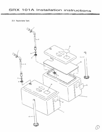
SRX 101 AInstallation instructions25 i Replenlshe( Tan" .,- ,\912
-INSTALLATION iNSTRUCTIONS AND PRECAUTIONSn. Installation Instructions andPrecautlons13-1. Space Requirements noTrle accompanylI"IQ d;agram shows \he mInimUm space fequlrea 10 opelale. malOlal(),epa lf H'.eSAX· 101 A Any space smaller than lhese dimensions wlH resull n longel snuldown llm s dUf\ngmainlenance and repair----,--- L. 13-2. Setting the Main Unit in place {Reter 10 the msgram Below}CD Place 1M Ma01 Unil on tM Stano (OptIon). a oesk or a . on. bef'lcn Ihal the supply 6"0drainage valVes are easily accessibleCD Tne SAX· \ 01 A, when tilled wrtl) prOCeSSing SolullOnS. W91QI'1S apprOAlmale1y 6. 7 kgIhe suppon 10 be used ismor Maxe sure lilalIhan capable 01 ceB(lno IhlS welg nl ond also (ssis\anl 101McorrOSIVe eNecls ollhQ develeper (PH I \ I aoa flXQr lPH 4) chemIcals.Q) 00l'IO\inSlall he processos In nIgh vlb(a\lon areas or wtlere il cannol De p!operlyle eleaCD Place Ihe SRX·IOIA al a height /rom lhe IlOor lhal luthlls bOln or lhe lollowlng corKlil'Ons:l. The liqulO sur1ace ()sidethe replenisher tank IS beloW the lull marXs 01 the ma,nU(\IIplocessH'9 13nlls.b i he 1000 the maIn Un!: suppor1 IS I&SS Ihan '30cm Irem Ihe IIOOf or olr"l61 sunace wtlere lhe1replel\lsn lank IS SiB nOingB,f'ld,Mj,----.--l:li\:--------P- :.-.Tape[ ----. )Ma-. ,30 ;'"Oe'll610pflr SupplyHo!.e \Yello.'Fixer SupplyHoseIR loe"eIOD"" O(H'''' CIIOSf' (Yello .)f llel 0, a,nage110S0 (Red)Wale( Ofain HoSeInil&' .1'3f\ SO'lIe nl)WdSl'I().It" 0'1' D' a.C' a e HOse-, .r. IQf\I,
(0 Connecllhesupply hoses 10 the 25 liler replenisher lank.Yellow . 'OEV Supply Hose.Red' - -FIX Supply Hose.@ Use SNP·12·HSO to clamp the hoses 10 lhe lankNOTE:00 not exlendanyOf the hoses more Ihan 5 meters in lenglh. Illhese 12 mm diameter hosesare eXlended longer than 5 meters, Ihey lend to bend and collapse.13·4. Connecting the DraInage HosesCD Connecllhe drainage hoses 10 theDR.,4-1 "-' Yellow - OEV Drainage HoseRed FIX Drainage HoseTransparenl(Thick) Water Drainage Hose.Transparent(Thin) O. erilow Drainage Hose SIring the chemica! and waler drainage hoses so thaI no liquid will accumulate in the hosesbetween the main unit and the drainage lank or Ihe water drain.13·5. Power Source and WiringCD Changing the terminal Board to Meet Voltage RequirementsFollow these procedure in changing the connection to terminal boardTB, located on lhe lop of the eleclrical components unit.UL Version23 567II910 1 \12 13uo0 0 0 0 000 000 000o 0 000 000 000 000?fI(1)cDBladl Wire D For AC120V oull lS. connecl lerminals '5 and '8(1) For AC 11SV oullels. oonnecllermlnalS '5 and .7.
INSTALLATION INSTRUCTIONS AND PRECAUTIONS13-7. Water lines,,!Jj' . onnecl a reducer bushIng wilh a packIng to the laclhry's waler ullllly oullel'CD Conneclthe processor's water supply hose 10 the reducer bustling,Packln JFactl \y WalE rUlIh[y/Qullel/".SRX·l01A Walef Supply Hose -\Jg.nPF3I4PFI/2(:\) Acceptable Wash Waler Tempe/alureRequired Waler Flow,"--" .0.7- f.7 (0, 19-0,47gal )/min".ReqUIred Water PressuleG) II water" , .s'C -30t (4' 'F -86'F),,". . .",pr essure IS 0010'11' 29.4 a(O. 3kgl}/cm l , over 0,7e(029.4-784kpa(0 3-8kgf)/C101199al. )/mlO Wash waler Carnolbe mainlalned,In lhlS case. a mallun .'1lon may occur, Increase Ihe water plt!ssure ) II waler pressure is el ceeoing 784kpa(6k91 ,cm'. use 110'11' reSlnctor 10 reduce Ihe waterpressure.Excessi. e water pressure applie 1 10 the waler hne may cause tM damage 01 !he hosest J . Set11ng the Feed Tray In P\aceC'USC the pan.T\ead screws prOVIOP.d to anach the leed tray to the maIO u(\I1.(I. Controlpanel can oe anac/'led toSel l theSide whoicnI ell!1e1side01tile masnurll\more convenIent \0 operate, C'Onslc,1(:lIng lhe operatIng envlIonmenl1J.g,Cleanlng the RacksCD Remove the OEV and FIX rac\\s tram the maIn U(\II(1) Servo each rack(incl\Jdlog \he rOllers)lInsev,lIlhracks.wilh a weI sponge \0 remo. e any dlr1 or grim and thenpiain water Lean Ihe racks so lha,llhe remaInIng water can evacuale !rom lhe
INSTALLATION INSTRUCTIONS AND PRECAUTIONSD-l0.Leveling the Main Unit(i) Use a carpen\er's level. Turn \he adjustable legs supporting (he main unit 10 balance !heprocessor vertically and horizonlally.@If the carpenter's levelISnOl available. jill the tanks wilh a solu!;on up 10 the indicator mark,and check tl1 level 01 Ihe solution al 6 diUgrent pOlnls on the levehng hnes wnicl1 are localeda\ flg\1\ and lelllnner side ollhe DEV, FIX and WASH lank. and adjusl it neceSS8r'y'DEV Tank-------FIX TankWASH TanK The leveling line 10put \he carpenler'slavel.(3 pa1nls)--------" \IIr---'
INSTAllAnON INSTRUCTIONS AND PRECAUTIONS 13-11.Settlng theRBCk.SMake sure lhal thereISno e;Jl;cess waler remainingInlhe racks before sel1ing Ihem Inlo (hemain unil The rackS have been designed so Illal lhe DEV rack is set Ilfst. then Ihe FIX·WASH racK can be insened. They cannot be set in the reverse orderSal each (ael inlo rhe main unit so lhal Ihe arrowS and names on the rae\ exactly overlapIhe arrows and Ian. names on the main unil. (ReIer 10 Ihe diagram belOW)II Ihe arrows and names do not e1l3clly match, fhe racle. nbs will nOI slide Into lhelr groovesand the rackS will wobble in the lanks.OEV Rae\ .FIX·WASH RackIWASH TankIFIX Tan\ .Df:V Tank
DEv AaCkGrooveF IX/WASI1 Ra AS()I Alb13-12. Mixing the Proce lng Ch&mlcalaWhen Using lhe 25 L1ler RlOplenlshQr Tank, lollOw t e dlfectlon rhal come wIth each pack ordeveloper and ""e(
. . I V "f1"'"nu\,; I IONS AND PRECAUTIONSr').13. Filling therink,a, NOlmal PrOCedureCD ReMove /he lop cover 01 lhe main unitCD Close allihe drainage "alvinCD Op@f"I the laclhly's waler U\llrty valVeG) PluQ in tf'e pOWer @ - - The RUN 8ur on lamp on the comrOl panel will llgnt upHOlEDo nol plesstheRUN Bvt1On,RUN(j) P,esS5 and hold do-"wn the ReP'O"l hment Button (aboU1se ::ood ) unlJllhe REAOY La beOlni fluhingPr.u andhOld OO't'lln.OOU' 5.econdlllnTtle tankS will begin to De supplilld with PfOC89S QsolutIon unlll the READY LaIT'4 atop' 11a.aNng, \nd\cating tnallhe laoll.S ale MI.ThiS Plocess lakes abO\J1 22 mlnu\U a\ 50 Hz and .boU1 18 mlnult' 8\ 60 Hz C\ose the lop cover
INSTALLATION INSTRUCTIONS AND PRECAUTiONSb QUICK Proce hJ1e11 yoU are in a hurry 10 (ililhe tan\l.s, you can use the IUl1nel prOyided to lill the tanks manually.8eg in the tol1o'Hing procedures wllh only \he PE\{ rack sellO placeCD Push the OFF side (Oside) ollt'le power breakerCD Fill the FIX tank wilh solution up 10 the lull malk,CDbegin careful nol 10 splash any 01 lhesolution into Ihe DE" lank.NOTE Wash the 'unnel tholOughly a(te( useSerlhe fIX.WASH fa Inla 1M lank., being carelulllo llO splash any ollhe solution.G) Fill ltleOEVla" with solullOn \0 just slightly over1low the tank. Use the beaker pro't'lded 10 measure O\rt the specltied Quantilyt ell Pour the slanef into lhe DEV tank through the starter \uid inlet.r78 Illi) 01 slarte .NOTE "Air rock" may occur .fter finishing 1hts pfocedure,B& ,ure \0 .ct\",aI8 lhe Circulationpump to check If the solutions clreul.le normlllly.13-'4, Operation TestingCD Press lhe RUN Button ON . 1M RUN Lamp willligl1\ up.Q) Walt un\il the READY lamp lighlS up.hQ) Remove ,he main unit's top cover(3) As soon as the ploces ' is READY. inse" a lew sheels ollest lilm 'hroog lhe leed ,.a, andsocheck \he lollowlflg operal\ons :Are the rollers rolatlng m O\hly?b. Are \he processing sohftlOI"\S Ci(CUlating 'In the tankS?3.c Is ,he DEV tempe"'o'. a'lho ",,,oelIe,.' who" 'h6 READY lamp comes on'd. IS the lesl \lIm enleri09 thll proc ltSsor smoothly';e. Is Ihe ala,m soondlng aile' the tramng edge o.,ne "m ente" the p,ocesso,?(See p. SOl\. Are \nereany lea'l .s In PIPIng sy ;\em?
SRX 101 A Installation instructions. 25 . i . Replenlshe( Tan" .,- , \ 9 . 12 _ -INSTALLATION iNSTRUCTIONS AND PRECAUTIONS . n. Installation Instructions and Precautlons . 13-1. Space Requirements . Trle . accompanylI"IQ . d;agram . shows \he mInimUm space fequlrea 10 . opelale. malOlal() no,epa. lf . H'.e . SAX· 101 A Any space smaller than lhese dimensions wlH resull n longel .