Transcription
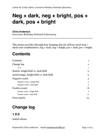
Hu ch01v4.fm Page 1 Thursday, February 12, 2009 10:14 AM1Electrons and Holesin SemiconductorsCHAPTER OBJECTIVESThis chapter provides the basic concepts and terminology for understandingsemiconductors. Of particular importance are the concepts of energy band, the twokinds of electrical charge carriers called electrons and holes, and how the carrierconcentrations can be controlled with the addition of dopants. Another group ofvaluable facts and tools is the Fermi distribution function and the concept of the Fermilevel. The electron and hole concentrations are closely linked to the Fermi level. Thematerials introduced in this chapter will be used repeatedly as each new device topic isintroduced in the subsequent chapters. When studying this chapter, please payattention to (1) concepts, (2) terminology, (3) typical values for Si, and (4) all boxedequations such as Eq. (1.7.1).The title and many of the ideas of this chapter come from a pioneering book,Electrons and Holes in Semiconductors by William Shockley [1], publishedin 1950, two years after the invention of the transistor. In 1956, Shockleyshared the Nobel Prize in physics for the invention of the transistor with Brattainand Bardeen (Fig. 1–1).The materials to be presented in this and the next chapter have been foundover the years to be useful and necessary for gaining a deep understanding of alarge variety of semiconductor devices. Mastery of the terms, concepts, and modelspresented here will prepare you for understanding not only the manysemiconductor devices that are in existence today but also many more that will beinvented in the future. It will also enable you to communicate knowledgeably withothers working in the field of semiconductor devices.1.1 SILICON CRYSTAL STRUCTURE A crystalline solid consists of atoms arranged in a repetitive structure. Theperiodic structure can be determined by means of X-ray diffraction and electronmicroscopy. The large cubic unit shown in Fig. 1–2 is the unit cell of the silicon1
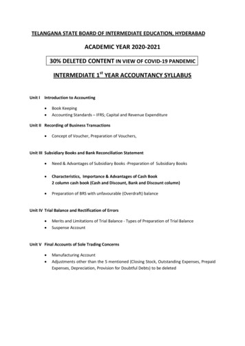
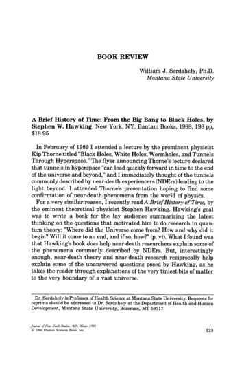
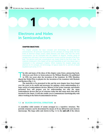
Hu ch01v4.fm Page 2 Thursday, February 12, 2009 10:14 AM2Chapter 1 Electrons and Holes in Semiconductors Inventors of the Transistor Born on three different continents (Brattain in Amoy, China; Bardeen in Madison,Wisconsin, USA; and Shockley in London, England), they all grew up in the UnitedStates and invented the transistor in 1947–1948 at Bell Telephone Laboratories.Brattain was an experimentalist while Bardeen and Shockley contributed more tothe concepts and theories. Their reflections on that historic event:“. after fourteen years of work, I was beginning to give up .”—Walter H. Brattain (1902–1987)“Experiments that led to the invention of the point-contact transistor by WalterBrattain and me were done in November and December, 1947, followed closely bythe invention of the junction transistor by Shockley.”—John Bardeen (1908–1991)“All of us who were involved had no doubt that we had opened a door to a newimportant technology. ”—William B. Shockley (1910–1988)FIGURE 1–1 Transistor inventors John Bardeen, William Shockley, and Walter Brattain (leftto right) at Bell Telephone Laboratories. (Courtesy of Corbis/Bettmann.)crystal. Each sphere represents a silicon atom. This unit cell is repeated in allthree directions many times to form a silicon crystal. The length of the unit cell,e.g., 5.43 Å in Fig. 1–2, is called the lattice constant.The most important information from Fig. 1–2 is the simple fact that each andevery silicon atom has four other silicon atoms as its nearest neighbor atoms. Thisfact is illustrated in Fig. 1–2 with the darkened cluster of a center atom having fourneighboring atoms. This cluster is called the primitive cell. Silicon is a group IVelement in the periodic table and has four valence electrons. These four electronsare shared with the nearest neighbors so that eight covalent electrons are associated
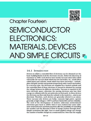
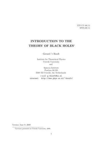
Hu ch01v4.fm Page 3 Thursday, February 12, 2009 10:14 AM1.1 Silicon Crystal Structure5.43 ÅFIGURE 1–2 The unit cell of the silicon crystal. Each sphere is a Si atom. Each Si atom hasfour nearest neighbors as illustrated in the small cube with darkened atoms. (Adapted fromShockley [1].) For an interactive model of the unit cell, see http://jas.eng.buffalo.edu/with each atom. The structure shown in Fig. 1–2 is known as the diamond structurebecause it is also the unit cell of the diamond crystal with each sphere representinga carbon atom. Germanium, the semiconductor with which the first transistor wasmade, also has the diamond crystal structure.Figure 1–3 introduces a useful system of denoting the orientation of thesilicon crystal. The cube in Fig. 1–3a represents the Si unit cell shown in Fig. 1–2 andeach darkened surface is a crystal plane. The (100) crystal plane in the leftmostdrawing in Fig. 1–3a, for example, is simply the plane in Fig. 1–2 closest to thereader. It intersects the x axis at 1 lattice constant and the y and z axes at infinity.One might refer to this plane as the 1 plane. However, it is standard practice torefer to it as the (1/1 1/ 1/ ), or the (100), plane. In general, the (abc) planeintersects the x, y, and z axes at 1/a, 1/b, and 1/c lattice constants. For example, the(011) plane in the middle drawing in Fig. 1–3a intersects the x axis at infinity andthe y and z axes at 1 lattice constant. The numerals in the parentheses are called theMiller indices. The related symbol [abc] indicates the direction in the crystal normalto the (abc) plane. For example, when an electron travels in the [100] direction, ittravels perpendicular to the (100) plane, i.e., along the x axis.Figure 1–3b shows that the silicon wafers are usually cut along the (100) plane toobtain uniformity and good device performance. A flat or a notch is cut along the (011)plane in order to precisely and consistently orient the wafer as desired during devicefabrication. Different surface orientations have different properties such as the rate ofoxidation and the electronic quality of the oxide/semiconductor interface. Both thesurface orientation and the direction of current flow along the surface affect the speedperformance of a surface-base device such as metal-oxide-semiconductor field-effecttransistor (MOSFET, see Section 6.3.1). The most important semiconductor materialsused in microelectronics are crystalline. However, most everyday solids are not singlecrystals as explained in the sidebar in Section 3.7.3
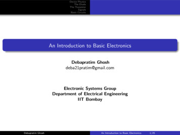
Hu ch01v4.fm Page 4 Thursday, February 12, 2009 10:14 AM4Chapter 1 Electrons and Holes in e(011)Flat(b)(c)FIGURE 1–3 (a) A system for describing the crystal planes. Each cube represents the unitcell in Fig. 1–2. (b) Silicon wafers are usually cut along the (100) plane. This sample has a(011) flat to identify wafer orientation during device fabrication. (c) Scanning tunnelingmicroscope view of the individual atoms of silicon (111) plane.1.2 BOND MODEL OF ELECTRONS AND HOLES Each silicon atom is surrounded by four nearest neighbors as illustrated by the shadedcluster in Fig. 1–2. We can represent the silicon crystal structure with the twodimensional drawing shown in Fig. 1–4. An Si atom is connected to each neighborwith two dots representing the two shared electrons in the covalent bond. Figure 1–4suggests that there are no free electrons to conduct electric current. This is strictly true
Hu ch01v4.fm Page 5 Thursday, February 12, 2009 10:14 AM1.2SiSiSiSiSiSiSiSiSi Bond Model of Electrons and HolesFIGURE 1–4 The silicon crystal structure in a two-dimensional representation.only at the absolute zero temperature. At any other temperature, thermal energy willcause a small fraction of the covalent electrons to break loose and become conductionelectrons as illustrated in Fig. 1–5a. Conduction electrons can move around in acrystal and therefore can carry electrical currents. For this reason, the conductionelectrons are of more interest to the operation of devices than valence electrons.An interesting thing happens when an electron breaks loose and becomesfree. It leaves behind a void, or a hole indicated by the open circle in Fig. 1–5a. Thehole can readily accept a new electron as shown in Fig. 1–5b. This provides anothermeans for electrons to move about and conduct currents. An alternative way tothink of this process is that the hole moves to a new location. It is much easier tothink of this second means of current conduction as the motion of a positive holethan the motion of negative electrons moving in the opposite direction just as it ismuch easier to think about the motion of a bubble in liquid than the liquidmovement that creates the moving bubble.In semiconductors, current conduction by holes is as important as electronconduction in general. It is important to become familiar with thinking of the holes asmobile particles carrying positive charge, just as real as conduction electrons aremobile particles carrying negative charge. It takes about 1.1 eV of energy to free acovalent electron to create a conduction electron and a hole. This energy can bedetermined, for example, from a photoconductivity experiment. When light shines on aSi sample, its conductivity increases because of the generation of mobile electrons andholes. The minimum photon energy required to induce photoconductivity is 1.1 eV.The densities of thermally generated electrons and holes in semiconductorsare generally very small at room temperature given that the thermal energy, kT, is26 meV at room temperature. A much larger number of conduction electrons can beintroduced if desired by introducing suitable impurity atoms—a process called GURE 1–5 (a) When a covalent electron breaks loose, it becomes mobile and can conductelectrical current. It also creates a void or a hole represented by the open circle. The hole canalso move about as indicated by the arrow in (b) and thus conduct electrical current.5
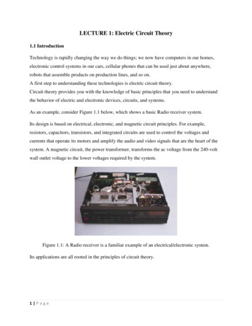
Hu ch01v4.fm Page 6 Thursday, February 12, 2009 10:14 AM6Chapter 1 Electrons and Holes in a)(b)FIGURE 1–6 Doping of a semiconductor is illustrated with the bond model. (a) As is adonor. (b) B is an acceptor.the semiconductor. For example, group V elements such as As shown in Fig. 1–6abring five valence electrons with each atom. While four electrons are shared with theneighboring Si atoms, the fifth electron may escape to become a mobile electron,leaving behind a positive As ion. Such impurities are called donors for they donateelectrons. Notice that in this case, no hole is created in conjunction with the creation ofa conduction electron. Semiconductors containing many mobile electrons and fewholes are called N-type semiconductors because electrons carry negative (N) charge.As and P are the most commonly used donors in Si.Similarly, when boron, a group III impurity, is introduced into Si as shown inFig. 1–6b, each B atom can accept an extra electron to satisfy the covalent bonds,thus creating a hole. Such dopants are called acceptors, for they accept electrons.Semiconductors doped with acceptors have many holes and few mobile electrons,and are called P type because holes carry positive (P) charge. Boron is the mostcommonly used acceptor in Si. In and Al are occasionally used.The energy required to ionize a donor atom (i.e., to free the extra electron andleave a positive ion behind) may be estimated by modifying the theory of theionization energy of a hydrogen atom,m0q 4E ion ------------- 13.6 eV28 ε0h 2(1.2.1)where m0 is the free electron mass, ε0 is the permittivity of free space, and h isPlanck’s constant. The modification involves replacing ε0 with 12ε0 (where 12 is therelative permittivity of silicon) and replacing m0 with an electron effective mass, mn ,which is a few times smaller than m0 as explained later. The result is about 50 meV.Because donors have such small ionization energies, they are usually fully ionized atroom temperature. For example, 1017cm–3 of donor atoms would lead to 1017cm–3 ofconduction electrons. The same conclusion also applies to the acceptors. GaAs, III–V Compound Semiconductors and Their Dopants GaAs and similar compound semiconductors, such as InP and GaN, are dominantin optoelectronic devices such as light-emitting diodes and semiconductor lasers(see Sections 4.13 and 4.14). GaAs also plays a role in high-frequency electronics (seeSections 6.3.2 and 6.3.3). Its crystal structure is shown in Fig. 1–7 and Fig. 1–8. Thesimilarity to the Si crystal is obvious. The shaded spheres represent As atoms and the
Hu ch01v4.fm Page 7 Thursday, February 12, 2009 10:14 AM1.2 Bond Model of Electrons and Holeslight spheres represent Ga atoms. Each Ga atom has four As neighbors and eachAs atom has four Ga neighbors. The lattice constant is 5.65 Å. Ga is a group IIIelement and As is a group V element. GaAs is known as a III–V compoundsemiconductor, as are GaP and A1As, which also have the same crystal structure asillustrated in Fig. 1–7.It is probably obvious that group VI elements such as S and Se can replace thegroup V As and serve as donors in GaAs. Similarly, group II elements such as Zn canreplace Ga and serve as acceptors.But, are group IV elements such as Si and Ge donors or acceptors in GaAs?The answer is that they can be either donors or acceptors, depending on whether theysubstitute for Ga atoms (which have three valence electrons) or As atoms (whichhave five valence electrons). Such impurities are called amphoteric dopants. It turnsout that Si is a donor and Ge is an acceptor in GaAs because it is energetically morefavorable for the small Si atoms to substitute for the small Ga atoms and for thelarger Ge to substitute for the larger As.GaAsFIGURE 1–7 The GaAs crystal structure.FIGURE 1–8 Bond model of GaAs.GaAsGaAsGaAsGaAsGa7
Hu ch01v4.fm Page 8 Thursday, February 12, 2009 10:14 AM8Chapter 1 Electrons and Holes in SemiconductorsEmpty upper bands2pLowest (nearly) empty band(conduction band)2sHighest (nearly) filled band(valence band)Filled lower bands(a)(b)FIGURE 1–9 The discrete energy states of a Si atom (a) are replaced by the energy bands ina Si crystal (b).1.3 ENERGY BAND MODEL While the bond model described in the previous section is conceptually simple, it isnot complete enough for understanding semiconductor devices. The most usefulmodel involves the concept of energy bands.Recall that electrons in an atom occupy discrete energy levels as shown inFig. 1–9a. If two atoms are in close proximity, each energy level will split into twodue to the Pauli exclusion principle that states that each quantum state can beoccupied by no more than one electron in an electron system such as an atommolecule, or crystal. When many atoms are brought into close proximity as in acrystal, the discrete energy levels are replaced with bands of energy statesseparated by gaps between the bands as shown in Fig. 1–9b. One may think of anenergy band as a semicontinuum of a very large number of energy states.Naturally, the electrons tend to fill up the low energy bands first. The lower theenergy, the more completely a band is filled. In a semiconductor, most of the energybands will be basically totally filled (completely filled at absolute zero), while thehigher energy bands are basically totally empty. Between the (basically) totally filledand totally empty bands lie two bands that are only nearly filled and nearly empty asshown in Fig. 1–9b. They are of utmost interest to us. The top nearly filled band is calledthe valence band and the lowest nearly empty band is called the conduction band. Thegap between them is called the band gap. The electrons in a totally filled band do nothave a net velocity and do not conduct current, just as the water in a totally filled bottledoes not slosh about. Similarly, a totally empty band cannot contribute to currentconduction. These are the reasons the valence band and the conduction band are theonly energy bands that contribute to current flows in a semiconductor.1.3.1 Energy Band DiagramFigure 1–10 is the energy band diagram of a semiconductor, a small portion of Fig. 1–9.It shows the top edge of the valence band, denoted by Ev, and the bottom edge ofthe conduction band, denoted by Ec . The difference between Ec and Ev is the bandgap energy or energy gap, Eg . Clearly, Eg Ec – Ev. For silicon, the energy gap isabout 1.1 eV. The electrons in the valence band are those associated with the
Hu ch01v4.fm Page 9 Thursday, February 12, 2009 10:14 AM1.3 Energy Band ModelConduction bandEcBand gapEgEvValence bandFIGURE 1–10 The energy band diagram of a semiconductor. Photoconductor as Light Detector When light is absorbed by a semiconductor sample and electron–hole pairs are createdas shown in Fig. 1–11, the number of electrons and holes (and therefore the conductivityof the semiconductor) increase in proportion to the light intensity. By putting twoelectrodes on the semiconductor and applying a voltage between the electrodes, onecan measure the change in the semiconductor conductance and thus detect changes inlight intensity. This simple yet practical photodetector is called a photoconductor.ElectronEcPhotonsEgPhoton energy : hv EgEvHoleFIGURE 1–11 Eg can be determined from the minimum energy (hν) of photons that areabsorbed by the semiconductor.covalent bonds in the bond model discussed in the previous section, and theelectrons in the conduction band are the conduction or mobile electrons. The bandgap energies of some semiconductors are listed in Table 1–1 to illustrate their widerange. The band-gap energy has strong influence on the characteristics andperformance of optoelectronic devices (see Section 4.12.4 and Table 4–1). By mixingmultiple semiconductors, the band-gap energy can be precisely tuned to desiredvalues. This is widely practiced for optical semiconductor devices (see Section 4.13).The band-gap energy can be determined by measuring the absorption of lightby the semiconductor as a function of the photon energy, hv. The light is stronglyabsorbed only when hv is larger than Eg . The absorbed photon energy is consumedto create an electron–hole pair as shown in Fig. 1–12. As hv is reduced below Eg ,the specimen becomes transparent to the light. Eg can be determined by observingthis critical hv. Values of Eg listed in Table 1–1 are basically obtained in this way.TABLE 1–1 Band-gap energies of selected mondEg (eV)0.180.671.121.422.252.76.09
Hu ch01v4.fm Page 10 Thursday, February 12, 2009 10:14 AM10Chapter 1Electrons and Holes in Semiconductors EXAMPLE 1–1Measuring the Band-Gap EnergyIf a semiconductor is transparent to light with a wavelength longer than0.87 µm, what is its band-gap energy?SOLUTION:Photon energy of light with 0.87 µm wavelength is, with c being the speed oflight–348–19c1.99 10 ( J µ m )6.63 10 ( J s ) 3 10 m/sh ν h --- ---------------------------- -λ0.87 µ m0.87 µ m–191.99 10 ( eV µ m ) 1.24 ( eV µ m ) ------ -------------------------------------- 1.42 eV–190.87 µ m1.6 10 0.87 µ mTherefore, the band gap of the semiconductor is 1.42 eV. The semiconductor isperhaps GaAs (see Table 1–1).USEFUL RELATIONSHIP:1.24h ν ( eV ) ------------------λ (µm)The visible spectrum is between 0.5 and 0.7 µm. (Silicon and GaAs have bandgaps corresponding to the hv of infrared light. Therefore they absorb visiblelight strongly and are opaque.) Some semiconductors such as indium and tinoxides have sufficiently large Eg’s to be transparent to the visible light and beused as the transparent electrode in LCD (liquid crystal display) flat paneldisplays.Conduction bandEdDonor levelEcDonor ionizationenergyAcceptor levelEaValence bandEvFIGURE 1–12 Energy levels of donors and acceptors.1.3.2 Donors and Acceptors in the Band ModelThe concept of donors and acceptors is expressed in the energy band model in thefollowing manner. Although less important than Ec and Ev , two other energylevels are present in the energy band diagram, the donor energy level Ed and theacceptor energy level Ea (Fig. 1–12). Recall that it takes the donor ionizationenergy (about 50 meV) to free the extra electron from the donor atom into aconduction electron. Therefore, the donor electron, before the electron is freed,must occupy a state at about 50 meV below Ec. That is to say, Ec – Ed is the donorionization energy. Similarly, Ea – Ev is the acceptor ionization energy (i.e., the
Hu ch01v4.fm Page 11 Thursday, February 12, 2009 10:14 AM1.4 Semiconductors, Insulators, and ConductorsTABLE 1–2 Ionization energy of selected donors and acceptors in silicon.DonorsAcceptorsDopantSbPAsBAlInIonization energy, Ec – Ed or Ea – Ev (meV)3944544557160energy it takes for an acceptor atom to receive an extra electron from the valenceband, creating a hole there). Some donor and acceptor ionization energies insilicon are listed in Table 1–2 for reference. As, P, Sb, and B are the mostcommonly used dopants for silicon. Acceptor and donor levels with smallionization energies, such as these four, are called shallow levels. Deep levels can becreated with other impurities such as copper and gold, and they affect siliconproperties in very different ways (see Section 2.6).1.4 SEMICONDUCTORS, INSULATORS, AND CONDUCTORS Based on the energy band model, we can now understand the differences amongsemiconductors, insulators, and conductors. A semiconductor has a nearly filledvalence band and a nearly empty conduction band separated by a band gap asillustrated in Fig. 1–13a. The band diagram of an insulator is similar to that of asemiconductor except for a larger Eg , which separates a completely filled band anda completely empty band (see Fig. 1–13b). Totally filled bands and totally emptybands do not contribute to current conduction, just as there can be no motion ofliquid in totally filled jars and totally empty jars. A conductor has a quite differentenergy band diagram. As depicted in Fig. 1–13c, a conductor has a partially filledband. This is the conduction band of the conductor and it holds the conductionelectrons. The abundance of the conduction electrons makes the resistivity of atypical conductor much lower than that of semiconductors and insulators.Why do some materials have a partially filled band and are thereforeconductors? Each energy band can hold two electrons per atom.1 This is whyEcEg 9 eVEg 1.1 eVEmptyEcEv(a) Si, semiconductorEv(b) SiO2, insulatorTop ofconduction bandFilledEc(c) ConductorFIGURE 1–13 Energy band diagrams for a semiconductor (a), an insulator (b),and a conductor (c).1 This is a simplified picture. Actually, each band can hold two electrons per primitive cell, which maycontain several atoms. A primitive cell is the smallest repeating structure that makes up a crystal. Thedarkened part of Fig. 1–2 is the primitive cell of the Si crystal.11
Hu ch01v4.fm Page 12 Thursday, February 12, 2009 10:14 AM12Chapter 1 Electrons and Holes in Semiconductorselemental solids with odd atomic numbers (and therefore odd numbers ofelectrons) such as Au, Al, and Ag are conductors. Elements with even atomicnumbers such as Zn and Pb can still be conductors because a filled band and anempty band may overlap in energy, thus leaving the combined band partially filled.These elements are known as semimetals.An insulator has a filled valence band and an empty conduction band thatare separated by a larger Eg. How large an Eg is large enough for the material tobe classified as an insulator? There is no clear boundary, although 4 eV would bean acceptable answer. However, even diamond, with Eg 6 eV (often cited as atextbook example of an insulator) exhibits semiconductor characteristics. It can bedoped N type and P type, and electronic devices such as rectifiers and transistorshave been made with diamond.One may say that semiconductors differ from insulators in thatsemiconductors can be made N type or P type with low resistivities throughimpurity doping. This characteristic of the semiconductors is very important fordevice applications.1.5 ELECTRONS AND HOLES Although the term electrons can be used in conjunction with the valence band as in“nearly all the energy states in the valence band are filled with electrons,” weshould assume that the term usually means conduction-band electrons. Holes arethe electron voids in the valence band. Electrons and holes carry negative andpositive charge ( q) respectively. As shown in Fig. 1–14, a higher position in theenergy band diagram represents a higher electron energy. The minimumconduction electron energy is Ec. Any energy above Ec is the electron kineticenergy. Electrons may gain energy by getting accelerated in an electric field andmay lose energy through collisions with imperfections in the crystal.A lower location in the energy diagram represents a higher hole energy asshown in Fig. 1–14. It requires energy to move a hole “downward” because that isequivalent to moving an electron upward. Ev is the minimum hole energy. We maythink of holes as bubbles in liquid, floating up in the energy band. Similarly, one maythink of electrons as water drops that tend to fall to the lowest energy states in theenergy band.1.5.1 Effective MassWhen an electric field, Ᏹ, is applied, an electron or a hole will accelerate according to– qᏱAcceleration ---------mnelectrons(1.5.1)qᏱAcceleration ------mpholes(1.5.2)In order to describe the motion of electrons and holes with the laws of motion ofthe classical particles, we must assign effective masses (mn and mp) to them. Theelectron and hole effective masses of a few semiconductors are listed in Table 1–3.
Hu ch01v4.fm Page 13 Thursday, February 12, 2009 10:14 AMIncreasing hole energyIncreasing electron energy1.5 Electrons and HolesElectron kinetic energyEcEvHole kinetic energyFIGURE 1–14 Both electrons and holes tend to seek their lowest energy positions.Electrons tend to fall in the energy band diagram. Holes float up like bubbles in water.TABLE 1–3 Electron and hole effective masses, mn and mp , normalized to the freeelectron mass.SiGeGaAsInAsAlAsmn /m00.260.120.0680.0232.0mp /m00.390.300.500.300.3The electrons and holes in a crystal interact with a periodic coulombic field inthe crystal. They surf over the periodic potential of the crystal, and therefore mnand mp are not the same as the free electron mass.A complete description of the electrons in a crystal must be based on theirwave characteristics, not just the particle characteristics. The electron wave functionis the solution of the three-dimensional Schrödinger wave equation [2].h 2– ---------- ψ V ( r )ψ E ψ2m 0(1.5.3)where h h 2 π is the reduced Planck constant, m0 is the free electron mass, V(r)is the potential energy field that the crystal presents to the electron in the threedimensional space, and E is the energy of the electron. The solution is of the formexp ( k r ) , which represents an electron wave k, called the wave vector, is equalat 2 π /electron wavelength and is a function of E. In other words, for each k there isa corresponding E (see Fig. 4–27 for a schematic E–k diagram). It can further beshown [2] that, assuming the E–k relationship has spherical symmetry, an electricfield, Ᏹ, would accelerate an electron wave packet with2qᏱ d EAcceleration – ---------------2h dk 2(1.5.4)In order to interpret the acceleration in the form of F/m, it is convenient tointroduce the concept of the effective mass2hEffective mass -----------------------22d E dk(1.5.5)13
Hu ch01v4.fm Page 14 Thursday, February 12, 2009 10:14 AM14Chapter 1 Electrons and Holes in SemiconductorsEach semiconductor material has a unique E–k relationship (due to theunique V(r)) for its conduction band and another unique E–k relationship for itsvalence band. Therefore, each semiconductor material has its unique mn and mp.The values listed in Table 1–3 are experimentally measured values. Thesevalues agree well with the effective masses obtained by solving the Schrödingerwave equation with computers.1.5.2 How to Measure the Effective Mass2If you wonder how one may measure the effective mass of electrons or holes in asemiconductor, let us study a powerful technique called cyclotron resonance.Consider an electron in an N-type semiconductor located in a magnetic field,B, as shown in Fig. 1–15. A moving electron will trace out a circular path in a planenormal to B. (In addition, there may be electron motion parallel to B. We mayignore this velocity component for the present analysis). The magnetic field exerts aLorentzian force of qvB, where v is the electron velocity and B is the magnetic fluxdensity. Equating this force to the centripetal force corresponding to the circularmotion with radius r, we obtain2mnv------------ qvBr(1.5.6)qBrv --------mn(1.5.7)The frequency of the circular motion isvqBf cr -------- ------------2πr2 π mn(1.5.8)This is the cyclotron resonance frequency. Notice that the resonance frequencyis independent of r and ν. Now, if a circularly polarized electric field of the samefrequency fcr (typically in the gigahertz range) is applied to this semiconductor, theB MicrowaveFIGURE 1–15 The motion of electrons in an N-type semiconductor in the presence of amagnetic field, B, and a microwave with rotating electric field (the direction of rotation isindicated by the arrow).2 This section may be omitted in an accelerated course.
Hu ch01v4.fm Page 15 Thursday, February 12, 2009 10:14 AM1.6 Density of Stateselectrons will strongly absorb the microwave energy. They do so by accelerating to ahigher velocity and tracing circles of increasing radius [see Eq. (1.5.7)] withoutchanging their frequency of circular motion [see Eq. (1.5.8)], losing the energiesthrough collisions, and starting the accelerati
every silicon atom has four other silicon atoms as its nearest neighbor atoms. This fact is illustrated in Fig. 1–2 with the darkened cluster of a center atom having four neighboring atoms. This cluster is called the primitive cell. Silicon is a group IV element in the periodic table and has four