Transcription
ECK-10 REV-O 091416.qxp ECK-10 9/14/16 2:49 PM Page 1BASIC ELECTRONIC COMPONENTSMODEL Transformers(not included)Instruction Manualby Arthur F. Seymour MSEEIt is the intention of this course to teach the fundamental operation of basicelectronic components by comparison to drawings of equivalent mechanicalparts. It must be understood that the mechanical circuits would operate muchslower than their electronic counterparts and one-to-one correlation can neverbe achieved. The comparisons will, however, give an insight to each of thefundamental electronic components used in every electronic product.ELENCO Copyright 2016, 1994 by ELENCO Electronics, Inc. All rights reserved.Revised 2016REV-ONo part of this book shall be reproduced by any means; electronic, photocopying, or otherwise without written permission from the publisher.753254
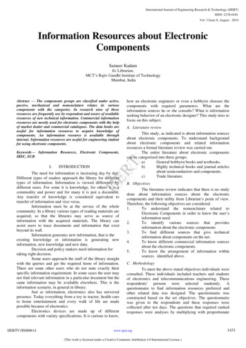
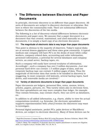
ECK-10 REV-O 091416.qxp ECK-10 9/14/16 2:49 PM Page 2RESISTORSRESISTORS, What do they do?The electronic component known as the resistor isbest described as electrical friction. Pretend, for amoment, that electricity travels through hollow pipeslike water. Assume two pipes are filled with waterand one pipe has very rough walls. It would be easyto say that it is more difficult to push the waterthrough the rough-walled pipe than through a pipewith smooth walls. The pipe with rough walls couldbe described as having more resistance tomovement than the smooth one.Electrons flow through materials when a pressure(called voltage in electronics) is placed on one endof the material forcing the electrons to “react” witheach other until the ones on the other end of thematerial move out. Some materials hold on to theirelectrons more than others making it more difficultfor the electrons to move. These materials have ahigher resistance to the flow of electricity (calledcurrent in electronics) than the ones that allowelectrons to move easily. Therefore, earlyexperimenters called the materials insulators if theyhad very high resistance to electon flow andconductors if they had very little resistance toelectron flow. Later materials that offered a mediumamount of resistance were classified assemiconductors.Pioneers in the field of electronics thought electricitywas some type of invisible fluid that could flowthrough certain materials easily, but had difficultyflowing through other materials. In a way they werecorrect since the movement of electrons through amaterial cannot be seen by the human eye, evenwith the best microscopes made. There is asimilarity between the movement of electrons inwires and the movement of water in the pipes. Forexample, if the pressure on one end of a water pipeis increased, the amount of water that will passthrough the pipe will also increase. The pressure onthe other end of the pipe will be indirectly related tothe resistance the pipe has to the flow of water. Inother words, the pressure at the other end of thepipe will decrease if the resistance of the pipeincreases. Figure 1 shows this relationshipgraphically.Water TankLow ResistancePipeHigh ResistancePipe (rough walls)When a person designs a circuit in electronics, it isoften necessary to limit the amount of electrons orcurrent that will move through that circuit eachsecond. This is similar to the way a faucet limits theamount of water that will enter a glass each second.It would be very difficult to fill a glass withoutbreaking it if the faucet had only two states, wideopen or off. By using the proper value of resistancein an electronic circuit designers can limit thepressure placed on a device and thus prevent itfrom being damaged or destroyed.SUMMARY:The resistor is an electroniccomponent that has electrical friction. This frictionopposes the flow of electrons and thus reduces thevoltage (pressure) placed on other electroniccomponents by restricting the amount of current thatcan pass through it.High PressureThrough SameSize OpeningLow PressureFigure 1-1-
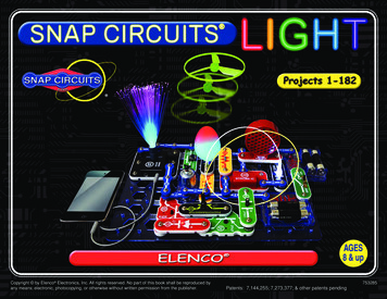
ECK-10 REV-O 091416.qxp ECK-10 9/14/16 2:49 PM Page 3RESISTORSRESISTORS, How are they made?The value of wirewound resistors remain fairly flatwith increasing temperature, but change greatly withfrequency. It is also difficult to precisely control thevalue of the resistor during construction so theymust be measured and sorted after they are built.There are many different types of resistors used inelectronics. Each type is made from differentmaterials. Resistors are also made to handledifferent amounts of electrical power. Someresistors may change their value when voltages areplaced across them. These are called voltagedependent resistors or nonlinear resistors. Mostresistors are designed to change their value whenthe temperature of the resistor changes. Someresistors are also made with a control attached thatallows the user to mechanically change theresistance. These are called variable resistors orpotentiometers. Figure 2 shows physical shapes ofsome different types of resistors.Ceramic RodWireProtective CoatingCarbon CompositionEnd CapFigure 3THE CARBON COMPOSITION RESISTORCarbon FilmFigure 2By grinding carbon into a fine powder and mixing itwith resin, a material can be made with differentresistive values. Conductive leads are placed oneach end of a cylinder of this material and the unit isthen heated or cured in an oven. The body of theresistor is then painted with an insulating paint toprevent it from shorting if touched by anothercomponent. The finished resistors are thenmeasured and sorted by value (Figure 4). If theseresistors are overloaded by a circuit, their resistancewill permanently decrease. It is important that thepower rating of the carbon composition resistor isnot exceeded.VariableTHE WIREWOUND RESISTORThe first commercial resistors made were formed bywrapping a resistive wire around a non-conductingrod (see Figure 3). The rod was usually made ofsome form of ceramic that had the desired heatproperties since the wires could become quite hotduring use. End caps with leads attached were thenplaced over the ends of the rod making contact tothe resistive wire, usually a nickel chromium alloy.Insulating Paint-2-Carbon & ResinMixtureFigure 4Conductive Wire
ECK-10 REV-O 091416.qxp ECK-10 9/14/16 2:49 PM Page 4RESISTORSCARBON FILM RESISTORSTHE VARIABLE RESISTORWhen a resistor is constructed so its value can beadjusted, it is called a variable resistor. Figure 6shows the basic elements present in all variableresistors. First a resistive material is deposited on anon-conducting base. Next, stationary contacts areconnected to each end of the resistive material.Finally, a moving contact or wiper is constructed tomove along the resistive material and tap off thedesired resistance. There are many methods forconstructing variable resistors, but they all containthese three basic principles.Carbon film resistors are made by depositing a verythin layer of carbon on a ceramic rod. The resistor isthen protected by a flameproof jacket since this typeof resistor will burn if overloaded sufficiently. Carbonfilm resistors produce less electrical noise thancarbon composition and their values are constant athigh frequencies. You can substitute a carbon filmresistor for most carbon composition resistors if thepower ratings are carefully observed. Theconstruction of carbon film resistors requiretemperatures in excess of 1,000OC.Thin Layerof ResistiveMaterialCarbon FilmCeramic RodFigure 5Non-conductiveBase MaterialWiperContactMovableArmFlameproof JacketStationaryContactMETAL OXIDE RESISTORSMetal oxide resistors are also constructed in asimilar manner as the carbon film resistor with theexception that the film is made of tin chloride attemperatures as high as 5,000OC. Metal oxideresistors are covered with epoxy or some similarplastic coating. These resistors are more costly thanother types and therefore are only used when circuitconstraints make them necessary.LeadsFigure 6METAL FILM RESISTORSMetal film resistors are also made by depositing afilm of metal (usually nickel alloy) onto a ceramicrod. These resistors are very stable withtemperature and frequency, but cost more than thecarbon film or carbon composition types. In someinstances, these resistors are cased in a ceramictube instead of the usual plastic or epoxy coating.-3-
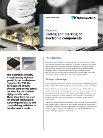
ECK-10 REV-O 091416.qxp ECK-10 9/14/16 2:49 PM Page 5RESISTORSRESISTOR VALUES AND MARKINGSThe unit of measure for resistance is the ohm, whichis represented by the Greek letter W. Beforetechnology improved the process of manufacturingresistors, they were first made and then sorted. Bysorting the values into groups that represented a 5%change in value, (resistor values are 10% apart),certain preferred values became the standard forthe electronics industry. Table 1 shows the standardvalues for 5% resistors.102247112451122756133062153368Table 1163675183982Note: If the third ring is gold, you multiply the firsttwo digits by 0.1 and if it is silver, by 0.01. Thissystem can identify values from 0.1W to as high as91 x 109, or 91,000,000,000W. The amount of powereach resistor can handle is usually proportional tothe size of the resistor. Figure 8 shows the actualsize and power capacity of normal carbon filmresistors, and the symbols used to representresistors on schematics.2043911/8 Watt1/4 Watt1/2 WattResistors are marked by using different colored ringsaround their body (see Figure 7). The first ringrepresents the first digit of the resistor’s value. Thesecond ring represents the second digit of theresistor’s value. The third ring tells you the power often to multiply by. The final and fourth ring representsthe tolerance. For example, gold is for 5% resistorsand silver for 10% resistors. This means the value ofthe resistor is guaranteed to be within 5% or 10% ofthe value marked. The colors in Table 2 are used torepresent the numbers from 0 to 9.RedVioletOrangeGold27 X 103 27,000 W,with 5% ToleranceFigure WhiteVALUE0123456789Table 2-4-Resistor SymbolsRegularFigure 8Variable
ECK-10 REV-O 091416.qxp ECK-10 9/14/16 2:49 PM Page 6RESISTORSSELF TESTTHEORYCircle the letter that best fits the description.6. A resistor that is made by wrapping a wire around aceramic rod:a) Carbon Filmc) Thermistorb) Carbon Composition d) Wirewound1. A flow of electrons through a material:a) Voltagec) Currentb) Resistanced) Conductance2. The pressure that pushes electrons through amaterial:a) Voltagec) Conductionb) Currentd) Resistance7. A resistor made by heating powder and resin in anoven:a) Carbon Filmc) Thermistorb) Carbon Composition d) Wirewound3. A material that has very high resistance to electronflow:a) Conductorc) Resistorb) Semiconductord) Insulator8. A resistor made by depositing a very thin layer ofresistive material on a ceramic rod:a) Carbon Filmc) Thermistorb) Carbon Composition d) Wirewound4. A material that allows electrons to flow easily:a) Conductorc) Resistorb) Semiconductord) Insulator9. One of the preferred values for a 5% resistor:a) 4000Wc) 77Wb) 560Wd) 395W5. A material that produces electrical friction and restrictsthe flow of electrons:a) Conductorc) Resistorb) Semiconductord) InsulatorPRACTICE10. The amount of wattage a resistor can handle isdetermined by:a) Valuec) Currentb) Voltaged) SizeOpen the bag marked “resistors” and fill in the table below.Color 1Color 2Color 3Color 4EXTRA CREDITValuePercentWattageUsing a razor blade or sharp knife, scrape away the paint on the body of one resistor and determine the type ofconstruction used to make it. Try and determine all of the materials used including the metals used to make theleads.-5-
ECK-10 REV-O 091416.qxp ECK-10 9/14/16 2:50 PM Page 7CAPACITORSCAPACITORS, What do they do?Capacitors act the same as the pipe in Figure 9.When a voltage (Electrical Pressure) is placed onone lead with respect to the other lead, electronsare forced to “pile up” on one of the capacitor’splates until the voltage pushing back is equal to thevoltage applied. The capacitor is then charged to thevoltage. If the two leads of that capacitor areshorted, it would have the same effect as letting theplunger in Figure 9 move freely. The capacitor wouldrapidly discharge and the voltage across the twoleads would become zero (No Charge).Capacitors are components that can store electricalpressure (Voltage) for long periods of time. When acapacitor has a difference in voltage (ElectricalPressure) between its two leads it is said to becharged. A capacitor is charged by forcing a oneway (DC) current to flow through it for a short periodof time. It can be discharged by letting an oppositedirection current flow out of the capacitor. Considerfor a moment the analogy of a water pipe that has arubber diaphragm sealing off each side of the pipeas shown in Figure 9.What would happen if the plunger in Figure 9 waswiggled in and out many times each second? Thewater in the pipe would be pushed by the diaphragmthen sucked back by the diaphragm. Since themovement of the water (Current) is back and forth(Alternating) it is called an Alternating Current or AC.The capacitor will therefore pass an alternatingcurrent with little resistance. When the push on theplunger was only toward the diaphragm, the wateron the other end of the diaphragm moved justenough to charge the pipe (transient current). Justas the pipe blocked a direct push, a capacitor clocksdirect current (DC). An example of alternatingcurrent is the 60 cycle (60 wiggles each second)current produced when you plug something into awall outlet.Pipe Filled with WaterPlungerRubber DiaphragmSealing Center of PipeFigure 9If the pipe had a plunger on one end, as shown inFigure 9, and the plunger was pushed toward thediaphragm, the water in the pipe would force therubber to stretch out until the force of the rubberpushing back on the water was equal to the force ofthe plunger. You could say the pipe is charged andready to push the plunger back. In fact, if theplunger is released it will move back to its originalposition. The pipe will then be discharged or with nocharge on the diaphragm.SUMMARY: A capacitor stores electrical energywhen charged by a DC source. It can passalternating current (AC), but blocks direct current(DC) except for a very short charging current, calledtransient current.-6-
ECK-10 REV-O 091416.qxp ECK-10 9/14/16 2:50 PM Page 8CAPACITORSCAPACITORS, How are they made?pressure (low capacitance, but high workingvoltage). By making the pipe larger and keeping thestiff rubber we can achieve a device that holds alarge amount of water and withstands a high amountof pressure (high capacitance, high working voltage,large size). These three types of water pipes areillustrated in Figure 12. The pipes follow the rule thatthe capacity to hold water, (Capacitance) multipliedby the amount of pressure they can take (Voltage)determines the size of the pipe. In electronics theCV product determines the capacitor size.There are many different types of capacitors used inelectronics. Each type is made from differentmaterials and with different methods. Capacitors arealso made to handle different amounts of electricalpressure or voltage. Each capacitor is marked toshow the maximum voltage that it can withstandwithout breaking down. All capacitors contain thesame fundamental parts, which consist of two ormore conductive plates separated by anonconductive material. The insulating materialbetween the plates is called the dielectric. The basicelements necessary to build a capacitor are shownin Figure 10.Paper or Plastic InsulatorLead 1Conductive PlateLead 2Nonconductive MaterialFigure 10Lead 1Lead 2Figure 11THE METAL FOIL CAPACITORPerhaps the most common form of capacitor isconstructed by tightly winding two foil metal platesthat are separated by sheets of paper or plastic asshown in Figure 11. By picking the correct insulatingmaterial the value of capacitance can be increasedgreatly, but the maximum working voltage is usuallylowered. For this reason, capacitors are normallyidentified by the type of material used as theinsulator or dielectric. Consider the water pipe withthe rubber diaphragm in the center of the pipe. Thediaphragm is equivalent to the dielectric in acapacitor. If the rubber is made very soft, it willstretch out and hold a large amount of water, but itwill break easily (large capacitance, but low workingvoltage). If the rubber is made very stiff, it will notstretch far, but will be able to withstand higherConductive FoilSoft RubberStiff RubberLarge CapacityLow PressureLow Capacitybut can withstandHigh PressureStiff RubberLarger SizeHigh Capacity and can withstand High Pressure-7-Figure 12
ECK-10 REV-O 091416.qxp ECK-10 9/14/16 2:50 PM Page 9CAPACITORSDIELECTRIC CONSTANT, What is it?THE VARIABLE CAPACITORThe dielectric (rubber diaphragm in the water pipeanalogy) in a capacitor is the material that canwithstand electrical pressure (Voltage) withoutappreciable conduction (Current). When a voltage isapplied to a capacitor, energy in the form of anelectric charge is held by the dielectric. In the rubberdiaphragm analogy the rubber would stretch out andhold the water back. The energy was stored in therubber. When the plunger is released the rubberwould release this energy and push the plungerback toward its original position. If there was noenergy lost in the rubber diaphragm, all the energywould be recovered and the plunger would return toits original position. The only perfect dielectric for acapacitor in which no conduction occurs and fromwhich all the stored energy may be recovered is aperfect vacuum. The DIELECTRIC CONSTANT (K)is the ratio by which the capacitance is increasedwhen another dielectric replaces a vacuum betweentwo plates. Table 3 shows the Dielectric Constant ofvarious materials.Air, at normal pressureAlcohol, ethyl (grain)BeeswaxCastor OilGlass flint density 4.5Glycerine1251.864.671056Mica7.5Paraffin wax2.25Paper, manilaPorcelainQuartzWater, distilledTable 3To make a variable capacitor, one set of stationaryaluminum plates are mounted to a frame with asmall space between each plate. Another set ofplates are mounted to a movable shaft anddesigned to fit into the space of the fixed plateswithout touching them. The insulator or dielectric inthis type of variable capacitor is air. When themovable plates are completely inside the fixedplates, the device is at minimum capacitance. Theshape of the plates can be designed to achieve theproper amount of capacitance versus rotation fordifferent applications. An additional screw is addedto squeeze two insulated metal plates together(Trimmer) and thus set the minimum amount ofcapacitance.TrimmerFixed PlatesShaft1.5MovablePlates4.4Frame281Figure 13-8-
ECK-10 REV-O 091416.qxp ECK-10 9/14/16 2:50 PM Page 10CAPACITORSCAPACITANCE, How is it calculated?The amount of charge a capacitor can hold(capacitance) is measured in Farads. In practice,one farad is a very large amount of capacitance,making the most common term used micro-farad orone millionth of a farad. There are three factors thatdetermine the capacitance that exist between twoconductive plates:0.01 inchGlass K 101. The bigger the plates are (Surface Area),the higher the capacitance. Capacitance(C) is directly proportional to Area (A).2. The larger the distance is between the twoplates, the smaller the amount ofcapacitance. Capacitance (C) is indirectlyproportional to distance (d).1 inch1 inch3. The larger the value of the dielectricconstant, the more capacitance (Dielectricconstant is equivalent to softness of therubber in our pipe analogy). Thecapacitance (C) is directly proportional tothe Dielectric Constant (K) of the insulatingmaterial. From the above factors, theformula for capacitance in Farads becomes:Figure 14CAPACITOR VALUES AND MARKINGSC 0.244K A(N-1) Picofarads *dC Capacitance in Picofarads (Farad x 10-12)K Dielectric ConstantA Area of one Plate in square inchesN Number of Platesd Distance between plates in inchesExample Calculation for Capacitor shown in Figure 14.C 2.24 x (1 x 1)(2 - 1) / (.01) 224 Picofarads or0.000224 Microfarads.* If A and d are in centimeters change 0.224 to0.0885. 16V 1010mF 25VB682KK2200mF 25VThe older styles of capacitors were marked withcolored dots or rings similar to resistors. In recentyears, the advances in technology has made iteasier to print the value, working voltage, tolerance,and temperature characteristics on the body of thecapacitors. Certain capacitors use a dielectric thatrequires markings to insure one lead is always keptat a higher voltage than the other lead. Figure 15shows typical markings found on different types ofcapacitors. Table 4 gives the standard values usedand the different methods for marking these icFigure 15AxialElectrolyticChip(nomarkings)
ECK-10 REV-O 091416.qxp ECK-10 9/14/16 2:50 PM Page FCAPACITORSCap. Value Typical 473R05R0681041542042R2221002204701000Tolerance (%)6Markings7 5% 10% 20%–10% 30%–10% 50%–20% 80%SPECIALJKMQTZATemperatureMarkingsNP0 { 10ppm / OC}N100 { 100ppm / OC}N220 { 220ppm / OC}N820 { 820ppm / OC}Y5FY5TY5VX5FZ5Umanufacturer may use an R to represent thedecimal point. The tolerance is usually printeddirectly on the capacitors. When it is omitted, thestandard tolerance is assumed to be 80% to –20%for electrolytics. Capacitance change withtemperature is coded in parts per million per degreeC, {N220 220/1,000,000 or .022%}, or by atemperaturegraph.Seemanufacturersspecifications for complete details.Capacitor markings vary greatly from onemanufacturer to another as the above table shows.Voltages may be marked directly (200V) or coded(2D). The value of capacitance may be markeddirectly on the part as shown in columns 4 and 5(note that .001mF and 1000mF have the samemarking, but the difference in size makes the valueobvious). The number 102 may also be used torepresent 1000 (10 2 zeros). In some instances theCAPACITOR SYMBOLSFigure 16 shows the schematic symbols used to representcapacitors. The symbol indicates that the capacitor ispolarized and the lead marked with the sign must alwayshave a higher voltage than the other lead. The curvedplate, plate with sides, and minus sign also indicate thecapacitor is polarized and these leads must always be at alower voltage than the other lead. The arrow crossingthrough the capacitor indicates of capacitance is variable.-10-Figure 16Standard –PolarizedVariable
ECK-10 REV-O 091416.qxp ECK-10 9/14/16 2:50 PM Page 12CAPACITORSSELF TESTTHEORYCircle the letter that best fits the description.1. A flow of electrons in one direction:a) AC Voltagec) Alternating Currentb) Direct Voltaged) Direct Current7. When electrons are forced onto one plate of acapacitor:a) Polarizationc) Storageb) Discharginga) Charging2. When two conductive plates are moved closertogether Capacitance will:a) Increasec) Stay the Sameb) Decreased) Vary Downwards8. A capacitor lead that is marked with a must always be:a) Groundedc) At higher voltage thanthe other leadb) At highest voltaged) b & c3. The name given to the material between a capacitor’splates:a) Airc) Conductorb) Dielectricd) Insulator9. A small disc capacitor marked 100 has a value of:a) 100mFc) 100pFb) .00001Fd) 100F4. Electrons flowing in and out of a wire:a) AC Voltagec) Alternating Currentb) Direct Voltaged) Direct Current10. A large electrolytic capacitor marked 100 has a valueof:a) 100mFc) 100pFb) .00001Fd) 100F5. If the size of the conductive plates is increased,capacitance will:a) Increasec) Stay the Sameb) Decreased) Vary Downwards6. A capacitor will block:a) AC Voltageb) Direct VoltagePRACTICE11. If a dielectric is changed from air to distilled water thecapacitance will:a) remain the samec) decreaseb) increase 81 timesd) drop in halfc) Alternating Currentd) Direct Current12. A dielectric that stores energy with no loss:a) Does not existc) Pure Glassb) Aird) A perfect vacuumOpen the bag marked “capacitors” and fill in the table below.TypeEXTRA CREDITCapacitanceValueWorkingVoltageTable 4What happens to the total capacitance if you connect twocapacitors as shown in Figure 17. Hint, use water pipeanalogy and try to calculate equivalent if one water pipe.-11-Polarized(Y/N)10mF20mFOtherMarkings? mFFigure 17
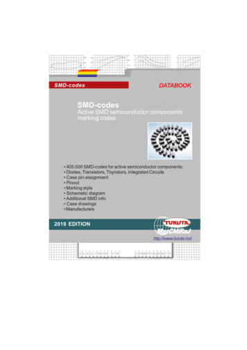
ECK-10 REV-O 091416.qxp ECK-10 9/14/16 2:50 PM Page 13INDUCTORSINDUCTORS, What do they do?The electronic component known as the inductor isbest described as electrical momentum. In our waterpipe analogy the inductor would be equivalent to avery long hose that is wrapped around itself manytimes (see Figure 18). If the hose is very long it willcontain many gallons of water. When pressure isapplied to one end of the hose, the thousands ofgallons of water would not start to move instantly. Itwould take time to get the water moving due toinertia (a body at rest wants to stay at rest). After awhile the water would start to move and pick upspeed. The speed would increase until the friction ofthe hose applied to the amount of pressure beingapplied to the water. If you try to instantly stop thewater from moving by holding the plunger, themomentum (a body in motion wants to stay inmotion) of the water would cause a large negativepressure (Suction) that would pull the plunger fromyour hands.Since Inductors are made by coiling a wire, they areoften called Coils. In practice the names Inductorand Coil are used interchangeably. From the aboveanalogy, it is obvious that a coiled hose will passDirect Current (DC), since the water flow increasesto equal the resistance in the coiled hose after anelapsed period of time. If the pressure on theplunger is alternated (pushed, then pulled) fastenough, the water in the coil will never start movingand the Alternating Current (AC) will be blocked.The nature of a Coil in electronics follows the sameprinciples as the coiled hose analogy. A coil of wirewill pass DC and block AC. Recall that the nature ofa Capacitor blocked DC and passed AC, the exactopposite of a coil. Because of this, the Capacitorand Inductor are often called Dual Components.Table 5 compares the properties of capacitors andinductors.Large Hose Filledwith WaterPlungerWater PipeFigure 18CapacitorInductorBlocks Direct CurrentBlocks Alternating CurrentVoltage in Capacitor cannot change instantlyCurrent in an Inductor cannot change instantlyPasses Alternating CurrentPasses Direct CurrentQuick Voltage change produces large CurrentStores Energy in Electric FieldCurrent leads VoltageQuick Current change produces large VoltageStores Energy in Magnetic FieldVoltage leads CurrentTable 5-12-
ECK-10 REV-O 091416.qxp ECK-10 9/14/16 2:50 PM Page 14INDUCTORSINDUCTORS, How are they made?the coil is increased, it will take more hose to form aloop, and the amount of water will thereforeincrease. More water means a larger “apparentmass”. Inductance will also increase in a coil if thecross sectional area increases. Inductance isdirectly proportional to area.In order to understand how inductors are made, wehave to change our water pipe analogy slightly toinclude the effect of magnetic fields. Consider twopipes filled with water and small magnets attachedto the walls of the pipes with rubber bands as shownin Figure 19. The moving magnets, due to theoriginal current, pull the magnets in the second pipeand force a small current to flow in the samedirection as the original current. When the rubberbands are fully stretched, the induced current willstop, even though the initial DC current is stillflowing. If the original current is an AC currenthowever, it will induce a continuous AC current inthe second pipe because the magnets will moveback and forth, pulling the magnets in the secondpipe back and forth.Coil 1Coil 2Figure 20Consider the affect of adding more turns to coiledpipe. The amount of material to push (mass) isincreased and the amount of linkage is increaseddue to more magnets available. This causes the“apparent mass” to increase at a greater rate thanwould be expected. When making an inductor, theactual inductance is directly proportional to thesquare of the number of turns.InducedCurrentInitialCurrentFigure 19Consider the two coiled pipes shown in Figure 20.When the pipe is stretched out (increased length) asin coil 1, the adjacent turns have little affect on eachother. In coil 2 (decreased length) the magnets ineach turn of the pipe are linking and the amount of“apparent mass” in the pipe seems to increase. Inan inductor, pushing the coiled wire closer togethercauses the inductance of the coil to also increase,and stretching the coil out will lower the inductanceof the coil. In other words, the inductance of a coil isindirectly proportional to its length. If the diameter of-13-The final factor to consider when making a coil is thecore material at the center of the coil. If our pipewrapped around a material that contained manymagnets, they would also link to the magnets in thepipe.Thiswouldincrease the “apparentmass” of the water inthe pipe. The tinymagnets in the corewould rotate as shownin Figure 21 and forcethe water to keepmoving in the samedirection. Placing aniron core at the center Many tinyof an inductor will magnetsOUTdirectly increase theinductance by anINamount equal to thepermeability of theFigure 21core material.
ECK-10 REV-O 091416.qxp ECK-10 9/14/16 2:50 PM Page 15INDUCTORSINDUCTANCE, How is it calculated?Reviewing how coils are made will show thefollowing:Where:L Inductance in microhenrys1. Inductance of a coil is indirectly proportional tothe length of the coil.N Number of turnsm Permeability of core material2. Inductance is directly proportional to the crosssectional area.A Cross-sectional area of coil, in square inch
BASIC ELECTRONIC COMPONENTS MODEL ECK-10 Instruction Manual by Arthur F. Seymour MSEE It is the intention of this course to teach the fundamental operation of basic electronic components by comparison to drawings of equivalent mechanical parts. It must be u