Transcription
POWERING PROGRESS THROUGHSCIENCE AND TECHNOLOGYB W R V IPBWR Vessel & Internals Project2000-163June 14, 2000Document Control DeskU. S. Nuclear Regulatory Commission11555 Rockville PikeRockville, MD 20852Attention:C. E. CarpenterSubject:Project 704 - Transmittal of "BWR Vessel and Internals Project, Weldability ofIrradiated LWR Structural Components (BWRVIP-45NP)," EPRI ReportTR-108707NP, May 2000.Reference:Letter from C. Terry to C. E. Carpenter, October 27, 1997: Transmittal of"BWR Vessel and Internals Project, Weldability of Irradiated LWR StructuralComponents (BWRVIP-45)," EPRI Report TR-108707, September 1997.Enclosed are two (2) copies of the subject report "BWR Vessel and Intemals Project, Weldability ofIrradiated LWR Structural Components (BWRVIP-45)," EPRI Report TR-108707, September 1997. Thisis the non-proprietary version of the document submitted to the NRC by the letter referenced above.If you have any questions on this subject please call Steve Lewis of Entergy, BWRVIPAssessment Committee Chairman, at (601) 368-5444.Sincerely,Carl TerryNiagara Mohawk Power CompanyChairman, BWR Vessel and Internals ProjectEnclosureCORPORATE HEADQUARTERS3412 Hillview AvenueI PaloAlto CA 94304-1395 USA 1 650.855-2000 1 Customer Service 800.313.3774 1 www.epri.com
CIF 12IBWR Vessel and Internals ProjectWeldability of Irradiated LWRStructural Components(BWRVIP-45NP)NON-PROPRIETARY INFORMATIONNOTICE: This report contains the non-proprietary information that is included inthe proprietary version of this report. The proprietary version of thisreport contains proprietary information that is the intellectual propertyof BWRVIP utility members and EPRI. Accordingly, the proprietaryreport is available only under license from EPRI and may not bereproduced or disclosed, wholly or in part, by any Licensee to anyother person or organization.
R E P 0R TS U M M A R YBWR Vessel and Internals ProjectWeldability of Irradiated LWR Structural Components(BWRVIP-45NP)Boiling Water Reactor Vessel and Internals Project (BWRVIP),formed in June 1994, is an association of utilities focused exclusivelyon BWR vessel and internals issues. This report describes workperformed to determine the effects of irradiation on the weldabilityof reactor internals.INTEREST CATEGORIESPiping, reactor vesseland internalsLicensing and safetyassessmentKEYWORDSBoiling water reactorIrradiationStress corrosion crackingVessel and internalsWeldabilityBACKGROUND A number of BWRs have experienced cracking in various internal components due to intergranular stress corrosion cracking. In some cases, thepreferred method for repairing these components is underwater welding. However,experience has shown that if the base metal is highly irradiated inferior welds canresult. At high fluences, helium is generated in the material due to transmutation ofboron and nickel through neutron absorption. During the welding process, thishelium is released and forms bubbles which cause cracks and inclusions in theweld.OBJECTIVES To determine the fluence threshold at which welding becomesproblematic and to develop a map of a typical BWR showing which regions areweldable and which are not.APPROACH The project team first conducted a literature search to determine thethreshold level of helium at which successful welds could be made. Next, the teamperformed a neutron transport calculation to establish the thermal neutron flux andhelium generation rates at all points in a typical BWR. Finally, the results of theabove tasks were combined to show calculated helium content at all points in thereactor at 1, 15 and 30 full power years.RESULTSContent DeletedEPRI Proprietary InformationEPRI PERSPECTIVE These results are useful in providing general guidance onthe acceptability of performing weld repairs on reactor internals. However, it mustbe noted that the helium content at which welding becomes problematic is not precisely defined. It appears to be dependent on a number of factors which are not wellquantified. In addition, methods for calculating the thermal neutron fluence (and thehelium generation) in the ex-core region are not as precise as for the in-core region.EPRIRS-108707EPRI RS-108707Electric Power Research InstituteElectric Power Research Institute
Improvements in the threshold definition and in the flux calculations wouldbe useful.PROJECTWOB501EPRI Project Manager: Warren BilaninBusiness Group: Nuclear Power GroupContractor: ORNLFor ordering information about this report, call the EPRI ProgramManager at (650) 855-2340.For membership information, call (650) 855-2514.
BWR Vessel and Internals ProjectWeldability of Irradiated LWR StructuralComponents (BWRVIP-45NP)TR-108707NPResearch Project 501Final Report, May 2000Prepared by:BWRVIP REPAIR COMMITTEEOAKRIDGE NATIONAL LABSAUBURN UNIVERSITYLOUISIANA STATE UNIVERSITYPrepared forBOILING WATER REACTOR VESSEL & INTERNALSELECTRIC POWERRESEARCH3412 Hillview Ave.Palo Alto, California 94304INSTITUTEPROJECT and
DISCLAIMER OF WARRANTIES AND LIMITATION OF LIABILITIESThis report was prepared by the organization(s) named below as an account of work sponsored orcosponsored by the BWR Vessel and Internals Project (BWRVIP) and the Electric Power ResearchInstitute, Inc. (EPRI).Neither BWRVIP, EPRI, any member of EPRI, any cosponsor, theorganization(s) named below, nor any person acting on behalf of any of them:(a) makes any warranty or representation whatsoever, express or implied, (i) with respect to the use ofany information, apparatus, method, process or similar item disclosed in this report, includingmerchantability and fitness for a particular purpose, or (ii) that such use does not infringe on orinterfere with privately owned rights, including any party's intellectual property, or (iii) that thisreport is suitable to any particular user's circumstance, or(b) assumes any responsibility for any damages or other liability whatsoever (including anyconsequential damages, even if BWRVIP, EPRI or any EPRI representative has been advised of thepossibility of such damages) resulting from your selection or use of this report or any information,apparatus, method, process or similar item disclosed in this report.Organization(s) that prepared this report:Oakridge National LabsLouisiana State UniversityAuburn UniversityBWRVIP Repair CommitteeORDERING INFORMATIONRequests for copies of this report should be directed to the BWRVIP Program Manager, 3412 Hillview Ave., Palo Alto, Ca.94304, (415) 855-2340.
Table of ContentsExecutive Sum m ary .ix1.0Introduction and Sum m ary Conclusions .12.0Literature Survey .73.0Flux Modeling .94.0Calculations of Helium Production .135.0Weldability Maps .15Appendix A: Detailed Results of Literature Survey .A-1Appendix B: Details of Flux Calculations .B-1iii
List of TablesTable 1-1Table 2-1:Boron concentration in commercial alloys used in research andin a U.S. nuclear power plant .16Summary of investigations relevant to the repair weldingof irradiated m aterials .18V
List of FiguresFigure 1-1Helium Generation from Boron and Nickel .Figure 3-1Layout of the upper section of representative BWR-4 plant, R-Z plane . 23Figure 3-2Layout of the lower section of representative BWRI4 plant, R-Z plane . 24Figure 3-3Segment of the representative BWR/4(Horizontal plane through core center.) .25Plot of fast neutron flux (E 1 Mev) in the R-Z planefor the upper reactor internals .26Plot of thermal neutron flux (E 0.4 eV) in the R-Z plane for theupper reactor internals .27Plot of fast neutron flux (E 1 Mev) in a horizontal planethrough the reactor vessel at the height of peak flux .28Plot of thermal neutron flux (E 0.4 eV) in a horizontal planethrough the reactor vessel at the height of peak flux .29Plot of fast neutron flux (E 1 MeV) in the R-Z planefor the lower reactor internals .30Plot of thermal neutron flux (E 0.4 MeV) in the R-Z planefor the lower reactor internals .31Figure 3-4Figure 3-5Figure 3-6Figure 3-7Figure 3-8Figure 3-922Figure 4-1Concentration of helium generated from boron and from nickel . 32Figure 5-1Atomic ppmhelium from 1 wt. ppm boron after one full power yearfor the upper half of the reactor .vii33
Figure 5-2Figure 5-3Figure 5-4Atomic ppm helium from 1 wt. ppm boron after 15 full power yearsfor the upper half of the reactor .34Atomic ppm ' helium from 1 wt. ppm boron after 30 full power yearsfor the upper half of the reactor .35Atomic ppm helium from 1 wt. ppm boron after 1 full power yearfor the lower half of the reactor .36Figure 5-5Atomic ppm helium from 1 wt. ppm boron after 15 full power years forthe low er half of reactor .37Figure 5-6Atomic ppm helium from 1 wt. ppm boron after 30 full power yearsfor the lower half of the reactor .38Figure 5-7Atomic ppm helium generated from nickel in an alloy containing 10%nickel for the upper half of the reactor in one full power year . 39Figure 5-8Atomic ppm helium from nickel in an alloy containing 10% nickelfor the upper half of the reactor in 15 full power years .40Atomic ppm helium from nickel in an alloy containing 10% nickel forthe upper half of the reactor in 30 full power years .41Atomic ppm helium from nickel in an alloy containing 10% nickelfor the lower half of the reactor in one full power year .42Atomic ppm helium from nickel in an alloy containing 10% nickelfor the lower half of the reactor in 15 full power years .43Atomic ppm helium from nickel in an alloy containing 10% nickelfor the lower half of the reactor in 30 full power years .44Figure 5-9Figure 5-10Figure 5-11Figure 5-12viii
Executive SummaryThe Boiling Water Reactor Vessel and Internals Project (BWRVIP) RepairCommittee has been developing a welded repair option for Reactor Pressure Vessel(RPV) internal components. This repair option may be necessary for somecomponents and configurations that are not suited to a mechanical repair, or wherereplacement requires structural welding.Previous experience in welding components from high fluence regions indicatesthat cracking can occur due to the presence of helium, produced by transmutation,in the base metal.This report provides a summary of available data on the effects of helium on weldrepairs and provides a methodology for defining the components, in a typical BWR,that can currently be repaired by welding without encountering degraded weldquality due to the presence of helium.ix
1.0 Introduction and Summary ConclusionsIn recent years, Boiling Water Reactors (BWRs) in the United States andOverseas have experienced stress corrosion cracking in a number of internalcomponents. Significant cracking has occurred at such locations as jet pumpriser pipes, core spray piping and core shrouds. In some cases the preferred, oronly, method of repairing or replacing the affected component requireswelding. For components located in regions of low neutron fluence, weldingis relatively straightforward although requiring significant effort fordeveloping automated welding equipment and qualification of procedures.In high fluence regions, however, welding is complicated by the deleteriouseffects caused by the presence of helium in the base metal. The helium isproduced in the metal primarily by transmutation of boron and nickel. Whenthe metal is liquefied during welding, the helium is released and causesporosity and cracking. Under high helium concentrations, the helium causesporosity along grain boundaries in the fusion zone. At lower concentrations,cracking occurs in the heat affected zone (HAZ) resulting from bubblesformed by migration of helium under the influence of high temperatures andstress.In recognition of this problem, the Repair Committee of the Boiling WaterReactor Vessel and Internals Project (BWRVIP) initiated a study to betterunderstand the implications of helium production on weld repairs. Theprimary objective of the work was to define which components in a typicalBWR could be repaired by welding without showing degraded weldperformance due to the presence of helium and which components wouldrequire additional work to confirm weldability or do not appear to beweldable. This objective was accomplished with a three-part approach:1. Perform a literature search to determine maximum amount ofhelium that can exist in the base metal before weldability becomesimpaired.2. Perform analyses to determine the amount of helium which wouldbe expected to exist in components located at various locations in atypical BWR. This was a two-step process which involved firstcalculating the neutron flux at each location and using these resultsto estimate the resulting helium concentration.3. Developing a "weldability" map showing which locations in thereactor could be welded without exhibiting the deleterious effectsdue to helium.The results of the literature search show that:I
Content DeletedEPRI Proprietary InformationThe literature search is described in Section 2 of this report; the neutron fluxand helium concentrations are discussed in Sections 3 and 4; and theweldability maps are shown in Section 5. In all cases, details of the variousdiscussions are contained in Appendices. Some introductory technical detailson the sources of helium in metals and the effect on weldability are discussedin the following paragraphsBackgroundHelium is produced by irradiation of metals in what are known as (n,a)reactions. In this reaction, a nucleus in a metal absorbs a neutron and emitsan alpha particle (which is identical to a helium nucleus). The helium atomthus produced is very stable and remains in the metal essentially forever. Forhigh energy neutrons (above about 10 MeV) this reaction can occur with alarge number of elements. However, for the thermal neutrons which occurin BWRs, those with energies less that approximately 0.5 eV, only a fewelements undergo a significant number of (n, a ) reactions. The mostprominent elements are boron and nickel.Boron is present in stainless steels and nickel base alloys in concentrationsfrom below 5 wt. ppm to 30 wt. ppm or higher. It is simply a naturallyoccurring impurity. Table 1-1 lists the boron contents of a number ofstructural alloys taken from literature and some measurements of archivematerials from an operating BWR. Boron has two naturally occurringisotopes 'B and GB, the latter of which comprises 19.9% of boron. Only 0 Bundergoes the (n,a) reaction with thermal neutrons, and its thermal crosssection is very high (3840 barns). Because of the high cross section, it burnsrather quickly, over 90% being burned to 4 He and 7Li by a thermal fluence of1021 n/cm'.Since helium is such a light atom, it is often presented in atomic percentrather than weight per cent to give a better feel for the amount present. One2
weight percent boron in iron is equivalent to 5.18 atomic percent. However,natural boron is only 19.9% "0B, so one weight percent boron is equivalent to1.03 atomic percent "0B. We will consider this equal to one. Since every atomof 0B will ultimately bum to 4He, one weight percent natural boron willultimately form one atomic percent helium. This is a convenient rule ofthumb that will be used later.Nickel becomes the larger source of helium at fluences beyond 1021 to 1022n/cm2 , depending upon the alloy. Its behavior is more complicated than thatof boron in that a two step reaction is necessary. Nickel-58 comprises 68.1% ofnatural nickel and undergoes the following reactions with thermal neutrons:"58Ni n -- 59Ni y"S9Ni n--566 Fe 4HeSince -9Ni is not naturally occurring, the production rate of helium is initiallyzero and increases as 59Ni accumulates. Unlike boron, there is a more thanadequate supply of nickel in any stainless steel or nickel alloy so that theconcentration of helium grows to many thousands of atomic ppm givensufficient thermal fluence. Figure 1-1 shows helium production from bothboron and nickel in stainless steel containing 10 wt. ppm boron as a functionof thermal neutron fluence. For type 304 stainless steel, the cross over pointwhere helium from nickel becomes greater than that from boron is at athermal fluence of on the order of 7 x 10²¹ n/cm2 .A third source of helium is important to the study of welding in irradiatedmaterials, although not an important source of helium in commercialBWR's. The method, known as the "tritium trick method", makes use of thefact that tritium, an isotope of hydrogen, decays to 3He. This source of heliumcan be used to study the effects of helium on materials and, in particular, onwelding. Tritium is diffused into the metal at elevated temperatures. Forrefractory metals, pressures below atmospheric are used, but for steels highpressures are required because of the lower solubility of hydrogen in iron.The metal is then cooled and aged at cryogenic temperatures until the desiredconcentration of helium is formed. It is then heated in a vacuum to permitthe tritium to diffuse out, leaving the helium. The 12.3 year tritium half-lifemakes helium doping a slow process, but by using a sufficient amount oftritium, significant helium generation rates can be achieved An advantage ofthe technique is that the material need not be neutron irradiated so that it isnot activated. This eliminates the need for radiation hot cells for handling.However, since there is always residual tritium, a proper facility forcontainment of small amounts of tritium must be used.3
Once helium is produced in sufficient quantities, it can cause serious defectsin a welding process due to the fact that it is insoluble in metals. Heliumdiffuses through the metal lattice and segregates at defects and grainboundaries in the form of bubbles which destroy cohesion at grain boundariesand eventually cause failure. When the material is welded, helium bubblesare formed and, at sufficiently high concentrations, can be trapped in thefusion zone. At lower concentrations, damage occurs in the HAZ. Here therapid diffusion associated with the high temperature allows rapidaccumulation of helium in bubbles at grain boundaries. The presence of atensile stress upon cooling is even more damaging since it makes largerbubbles thermodynamically more favorable. Rapid growth of the bubbles fedby rapidly diffusing helium leads to grain boundary cracking in the HAZ.Evidence suggests that there is a threshold of helium concentration abovewhich weldability becomes problematic. The literature search described in thefollowing section was undertaken to attempt to establish that threshold.4
2.0 Literature Survey of Repair WeldingA computer literature search was performed to determine the maximumamount of entrained helium which can be tolerated before adverse effects onweldability would be expected. The search was conducted on the followingdatabases: Weldasearch, 1967; Metadex, 1966; Engineered Materials Abstracts,1986; Energy Science and Technology, 1974; and Chemical Abstracts, 1967. Thekey word used to perform the search were: weld, irradiation, helium, steels,cracks and repair. The databases cover literature from 1966 to the present andinclude articles in all languages.A total of over 300 scientific articles was identified from which a carefulmanual screening narrowed the number of relevant articles to 49. These 49articles report the findings of 8 investigations that directly address the repairwelding of irradiated materials. A detailed description of the results of theliterature search is given in Appendix A. A summary of the findings of the 8relevant investigations is shown in Table 2-1. The following conclusions canbe drawn from the open literature:Content DeletedEPRI Proprietary Information5
Content DeletedEPRI Proprietary Information6
3.0 Flux ModelingFrom the preceding sections, it is evident that we need to determine thelocations in a reactor at which the accumulated helium concentration is lessthan approximately 1 appm. The first step in calculating heliumconcentration is to calculate the thermal neutron flux. Once flux is known asa function of energy and position in the reactor, the reaction rate with boronand nickel can be calculated as a function of position. From this, the timedependent accumulation of helium can be calculated and, from that, theweldability assessed.An accurate estimation of thermal flux in a specific BWR requires detailedcalculations using plant specific input data. However, in order to provide anestimate of helium production, calculations were performed to determine theflux at all points in a typical reactor. A BWR-4 was chosen as the type of plantto be modeled because of its predominance in the fleet.Content DeletedEPRI Proprietaryv InformationDetails of the calculations performed are described inAppendix B. A summary of the methods used and the pertinent results arepresented in the remainder of this section.Descriptionof the Flux CalculationsA complete three dimensional calculation of the flux everywhere within thereactor would be impractical. However, satisfactory results can be obtained bythe "synthesis method" in which three separate calculations are performedand then synthesized into a three dimensional picture of the flux. A twodimensional calculation is done in the RZ plane and a similar calculation inthe RO plane. A third one dimensional transport calculation is required inthe radial direction. The three flux distributions are then combined accordingto the following equation, the parameters of which are rigorously defined inAppendix B:1(R,0, Z) PR,e (R,e)x0 R,Z (R,Z)OR(R)where Roe "RE) channel" flux, obtained from a 2D transport calculation inRE) geometry;OR,Z "RZ channel" flux, obtained from a 2D transport calculation inRZ geometry;7
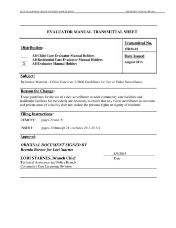
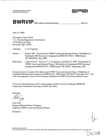
OR "R channel" flux, obtained from a ID transport calculation in Rgeometry, corresponding to a radial traverse along the core midplane in theRZ model.This synthesis approach is commonly used for reactor flux calculations and isthe approach recommended in NRC Draft Reg Guide DG-1053 (June 1996). Itis the preferred method for determining pressure vessel fluences. The DORTtransport code was used with a 47 group cross section library, SAILOR95.Content DeletedEPRI Proprietary Information. The upper and lower regions weretreated separately since the core midplane, which was chosen as the origin ofthe coordinate system, can be treated as a reflecting boundary. The R- thetamodel is shown in Figure 3-3. All components were modeled with knownpositions and average compositional number densities within each region.Content DeletedEPRI Proprietary InformationIt is important to realize that, although state of the art methods were used inthe calculations and that fast fluxes are predicted rather well in cases wheremeasurements have been made, thermal flux is difficult to predict. Thehomogenized nodes used in the calculations do not reflect the sometimeslarge local variations in thermal flux arising from the wide variations inthermal neutron cross sections between materials. Even in the small andrelatively simple cores of research reactors, fast flux is predicted well, butunanticipated variations in thermal flux always exist, as indicated by fluxmonitors.Results of Flux CalculationsResults of the calculations are shown in Figures 3-4 through 3-9. Figures 3-4and 3-5 show the R-Z dependence of the fast and thermal flux in the uppercore region. The various internal components are indicated by solid lines andcan be identified by reference back to Figure 3-1.Content DeletedEPRI Proprietary Information8
Figure 3-6 and 3-7 show the azimuthal (9) variation of the flux at the locationof peak axial fast and thermal flux (87.3 cm above the core midplane).Content DeletedEPRI Proprietary InformationFigures 3-8 and 3-9 show the axial variation in fast and thermal fluxrespectively for the lower core region.Content DeletedEPRI Proprietary InformationIn using the figures to estimate the thermal flux at a particular location, thefollowing guideline is suggested.Content DeletedEPRI Proprietary Information9
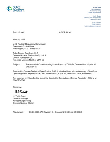
4.0 Calculations of Helium ProductionThe production of helium (appm) is shown in Figure 4-1 as a function ofthermal fluence. The curve for helium from boron is for an alloy containing1 wt. ppm boron. The curve for helium from nickel is for an alloy containing10 percent nickel. To estimate the helium concentration in a metal samplelocated at a particular location in a reactor, the following procedure may beused:Content DeletedEPRI Proprietary InformationFor convenience, the equations of the curves on Figure 4-1 are presentedbelow.For the production of helium from boron:Content DeletedEPRI Proprietary Informationand, for the production of helium from nickel:Content DeletedEPRI Proprietary InformationFor most situation in BWR locations of interest, the helium produced fromboron (steps 1-4) will give a sufficiently accurate estimate of the heliumII
concentration. However, for high fluence regions the contribution to thehelium concentration from the transmutation of nickel (steps 5-7) must alsobe considered.Content DeletedEPRI Proprietary Information12
5.0 Weldability MapsAnalyses were made to calculate helium concentrations throughout thetypical reactor for in-service lifetimes of 1, 15 and 30 years. Figures 5-1through 5-6 show helium concentrations from boron for a materialcontaining 1 ppm boron; figures 5-7 to 5-12 are similar contour plots forhelium produced from nickel in a material containing 10 percent nickel. Theregions of weldability may be quickly determined using these figures bymultiplying the results for boron by the boron concentration in the materialand the nickel results by the ratio of the nickel concentration to 10 percentand adding the results for boron and nickel. For time periods not close tothose in the graphs, the seven-step process described in Section 4 can be used.In using these results, it should be remembered that the fluence calculationswere for a "typical" reactor and that plant specific fluences may differsomewhat.Content DeletedEPRI Proprietary Information13
Tables15
Table 1-1 Boron concentrations in commercial alloys used in research and in a U.S. nuclear powerplantContent DeletedEPRI Proprietary Information16
Content DeletedEPRI Proprietary Information17
TABLE 2-1: Summary of Investigations Relevant to the Repair Welding of Irradiated MaterialsContent DeletedEPRI Proprietary Information
TABLE 2-1 (con't): Sunmary of Investigations Relevawt to tile Repair Welding of Irradiated MaterialsContent DeletedEPRI Proprietary Information
Figures21
N-)Content DeletedEPRI Proprietary InformationFig. 1-1 Helium generation from boron and nickel. (A typical AISI type304 stainless steel with 10% nickel and 10 wt. ppm boron is assumed.)
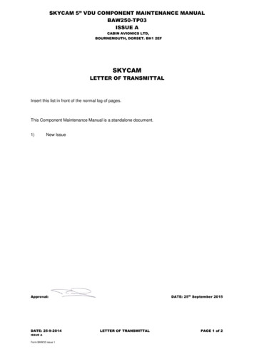
-I ISteam/Water Steam Separators375.-.LJShroud HeadR,.Exit Steam/Water11C0306Exit Steam/Water Spray SpargersC.02250Top Guide Exit SteamfWaterC, 1500Upper CoreA0zI-.Core 3Core 2C6p-p.75YECore 1Core 007I075iI'' I1 I150I "--I 2225:300375Radius (cm)Fig. 3-1 Layout of the upper section of representative BWR-4 plant, R-Zplane (Origin of Z coordinate is the core midplane)23450
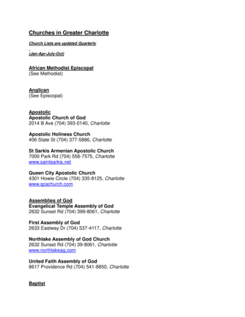
Core 0-25--\ Cole-100Co r -2Core -23-100-Core -3-75Ct2Water0"I . -Core Sunmonr Plate Inlet Water.c 71-2.0"\U-Inlet Water Control Rods/Guide Tubes-325-I-400Inlet Plenum-L5. . . .0'II75I11 . . .150III225II300I-I575Radius (cm)Fig. 3-2 Layout of the lower section of representative BWR/4 plant, RZ plane. (Origin of the Z coordinate is the core midplane.)24
Fig. 3-3 Segment of the representative BWR/4 (Horizontal planethrough core center.)0it7er Core0750150225300radius (cm)375450
Content DeletedEPRI Proprietary InformationFig. 3-4 Plot of fast neutron flux (E 1 Mev) in the R-Z plane for theupper reactor internals. (Solid lines indicate structures labeled in Fig.3-1.)26
Content DeletedEPRI Proprietary InformationFig. 3-5 Plot of thermal neutron flux (E 0.4 eV) in the R-Z plane forthe upper reactor internals. (Solid lines indicate structures labeled inFig. 3-1.)27
Fig. 3-6 Plot of fast neutron flux (E 1 Mev) in a horizontal pla
preferred method for repairing these components is underwater welding. However, experience has shown that if the base metal is highly irradiated inferior welds can result. At high fluences, helium is generated in the material due to transmutation of boron and nickel through neutron absorption. During the welding process, this