Transcription
Rajesh Kumar Ramaswamy and Dieter Ulber,Air Liquide Engineering & Construction,discuss the treatment of high conductivityprocess condensate from steam reformers.Around the world, plant owners are lookingto improve the operation of existingfacilities and expand their capacity aspart of strategies for growth. In theexample described in this article, one customer, aspart of a plant expansion project, was seeking
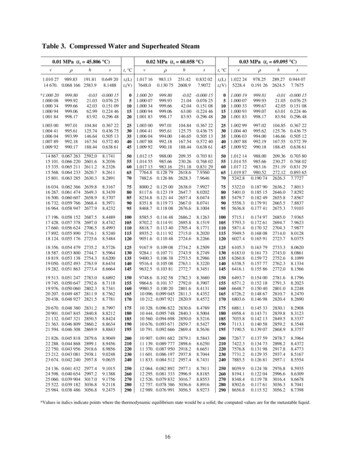
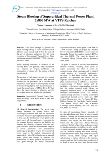
recommendations and practical support for the bestmethod of treating process condensate in a hydrogenproduction unit.Air Liquide Engineering & Construction wascontracted to design and select a new hydrogenproduction unit (HPU-2) capable of treating processcondensate which could not be treated in the existingplant (HPU-1) because the condensate quality deviatedfrom expected design figures and values, renderingthe process condensate flow scheme in HPU-1(Figure 1) unsuitable.After evaluation, a combined process was selectedto treat imported (HPU-1) and own processcondensate (HPU-2). The preferred solutionconsisted of the combination of segregatedsteam systems, a high pressure (HP) steamstripper and a process condensatevaporiser. The new unit was commissionedand performance tests successfullycompleted.Since there was no dedicated steamdrum to produce the export steam inHPU-1, poor process condensate qualityhad directly affected the export steamquality. The customer had to direct theprocess condensate to the waste waterplant, which in turn increased the makeupwater consumption.Figure 1. HPU-1 process condensate flow scheme (illustrated on asingle steam drum system).Process condensate of steamreformerProcess condensate from a steam methanereforming (SMR) plant includes variousimpurities such as dissolved ammonia(NH3), methanol, dissolved gases, organicsalts or acids, corrosion products, andother impurities from demineralised water.The quality of process condensate canbe determined from properties includingpH, electrical conductivity and dissolvedorganic carbons content. Quality can varybetween SMR plants and depends on plantdesign, especially the carbon monoxide(CO) shift technology, catalyst, feedstock,steam quality and chemical dosing scheme.While the recycling of processcondensate within an SMR plant will not bea challenge for the unit itself if chemicaldosing, monitoring and action plans exist,the quality of the exported steam mightnot be sufficient for use in condensingsteam turbines. However, the use of steamfrom recycled process condensate asprocess steam for SMR, for back-pressureFigure 2. Scheme for segregated steam systems.Table 1. Advantages and disadvantages of a segregated steam system vs a single steam drum systemAdvantagesDisadvantagesExport steam system is completely separated from the processcondensate and process steam systemCAPEX is higher due to additional equipment including secondsteam drum, second BFW pump and second de-aerator, plusinterconnecting pipingLarger plot area requiredHighest-quality steam suitable for condensing-type steam turbine,dependent only on demineralised water qualityDepending on plant design and operating parameters, e.g. turndown,the amount of process condensate recycling may be limitedVenting of ammonia and methanol to the atmosphere or additionalcombustion of de-aerator vent requiredReprinted from April 2019HYDROCARBONENGINEERING
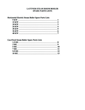
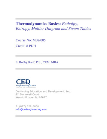
Table 2. Advantages and disadvantages of a single steam drum system with LP de-aeratorAdvantagesDisadvantagesLowest CAPEXVenting of ammonia and methanol to the atmosphere oradditional combustion of de-aerator vent requiredStandardised solution for low steam-quality consumers, likeback-pressure turbines, process steam or heating steamTable 3. Advantages and disadvantages of a process condensate vaporiser systemAdvantagesDisadvantagesExport steam system is completely separated from the processcondensate and process steam systemCAPEX is higher due to additional equipment requirements,including a second steam drum, second process condensate pumpand process condensate vaporiser and interchangerHighest-quality steam suitable for condensing-type steam turbine,dependent only on demineralised water qualityAdditional plot area requiredAll impurities in process condensate are recycled to the reformer asprocess steamNon-de-aerated process condensate will require stainless steelmaterial or high volumes of chemical dosing for pH adjustmentAll the process condensate can be recycled without restrictionAs much additional imported process condensate can be treated asheat is available in the clean export steamsteam turbines or as heating steam willtypically not be an issue as long as certainmaterial requirements are implemented.New hydrogen production unitThe solution chosen comprises aconventional hydrogen plant consisting ofzinc oxide purification, a top-fired SMR,high temperature shift conversion and apressure swing adsorption (PSA) unit.Available technologiesFigure 3. Scheme for process condensate vaporiser systems.Several methods are available for treatingprocess condensate, each with advantagesand limitations:nn Segregated steam systems for processcondensate and steam and forhigh-quality export steam.nn HP steam process condensate stripper.nn Low pressure (LP) steam processcondensate stripper.nn Process condensate vaporiser.nn Pressurised de-aerator.Selection should mainly be defined bycustomer requirements. Efficientperformance depends on the system beingtreated and on process requirements. Theselection of suitable technology for processcondensate treatment must consider criteriaincluding operating and capital cost, plantreliability and the quality requirements ofsteam consumers.Segregated steam systemsFigure 4. Scheme for HP steam stripper systems.Segregated steam systems (Figure 2) are usedin many hydrogen plants to produceHYDROCARBONENGINEERINGReprinted from April 2019
Table 4. Advantages and disadvantages of an HP steam stripper systemAdvantagesSteam quality is better than in the single steam systemMost of the impurities in process condensate are recycled to thereformer as process steamAll the process condensate can be recycled without restrictionDisadvantagesSome impurities remain in the stripped process condensate and endup in export steamSteam quality is insufficient for certain steam consumersConductivity is at least one order of magnitude higher than insolutions with complete separation of process condensate andexport steam systemsCAPEX is higher due to the additional equipment including steamdrum, second process condensate pump, HP steam stripper column,stripped condensate interchangerAdditional plot area requiredNon-de-aerated process condensate will require stainless steelmaterial or high volumes of chemical dosing for pH adjustmentRisk of process condensate stripper overflow and subsequent waterintroduction and damage of plantTable 5. Steam mass balance and quality – HP steam stripperStream no.Flowrate (kg/ hr)Operating pressure(barg)Operatingtemperature ( C)pHConductivity(uS/cm)Processcondensatefrom existingplant HPU-119035 00045Processcondensatefrom HPU-2ProcessHeating steam Process steam Strippedcondensate to to HP stripper from stripper condensatestripper topbottomtopfrom bottomStrippedcondensateafter cooling19132 7723219267 7723216133 8863316324 4033119377 2553219477 25531 .55081 .9144254237239209 7 2009 – 9.5 5009 – 9.5 5008.5 – 9.550 – 1508.5 – 9.58.5 – 9.550 – 1508.5 – 9.550 – 150–high-quality export steam to battery limit.To meet the export steam quality requiredfor condensing steam turbine operation, thedesign includes two separate steam systems:one to generate export steam, operatedexclusively with boiler feed water (BFW), andone for process steam, which operates withprocess condensate generated internallyfrom the hydrogen plant and additional BFWto balance the water demand for steamproduction.Table 1 explains the advantages anddisadvantages of this method compared tothe traditional single steam drum systemwith single LP de-aerator where BFW andprocess condensate are de-aerated.Single steam drum system withLP de-aeratorFigure 5. HPU-2 process condensate flow scheme.In this arrangement (Figure 1), processcondensate from the SMR plant isde-aerated in an LP de-aerator with process heat as theheating medium. De-aerated process condensate ispumped to the single steam drum to produce thesteam. The de-aerator is operated at around 0.2 bargand part of the carbon dioxide (CO2) and impuritieslike NH3 and methanol are vented to atmosphere.Using this method, it is not possible to produceReprinted from April 2019HYDROCARBONENGINEERINGhigh-quality steam suitable for use in condensingturbines. See Table 2 for the advantages anddisadvantages of this system.Process condensate vaporiserWith this method (Figure 3), process condensategenerated from the SMR plant is pumped to the
Table 6. Steam mass balance and quality – process condensate vaporiserStripped processcondensate inlet toprocess condensatevaporiserUnclean steam exportto battery limitHeating steam inletto process condensatevaporiserClean condensateoutlet to utilityStream no.197177173140Flowrate (kg/hr)11 41511 35510 75010 750Operating pressure (barg)30114242Operating temperature ( C)209194385385pH8.5 – 9.59 – 9.59 – 9.59 – 9.5Conductivity (uS/cm)50 – 15050 – 150 10 10Table 7. Steam mass balance and quality – other steam systemStream no.Flowrate (kg/hr)Operatingpressure (barg)Operatingtemperature ( eam drum16064 52334Heatingsteam toHP stripperbottomSteaminjected toreformerClean highpressuresuper-heatedsteam usedfor reformer172839742Strippedcondensateto processsteam drum16263 43728BFW toClean highclean steam pressuredrumsuper-heatedsteamproduced18617168 35267 785504719565 84034Clean highpressuresteam exportto batterylimit174178 7244216133 886332432542402453893852083858.5 – 9.550 – 1508.5 – 9.550 – 1509.2 – 9.50.19 – 9.5 109 – 9.5 108.5 – 9.550 – 1509 – 9.5 10––process condensate vaporiser after pre-heating withthe clean condensate generated from the processcondensate vaporiser in an interchanger.In the process condensate vaporiser, clean steamgenerated from the export steam drum is used as theheating medium. Process steam generated from theprocess condensate vaporiser is directly recycled tothe reformer with all impurities, which aredecomposed at high reforming temperature.Typically, the process condensate vaporiser is akettle-type or plate-and-shell-type heat exchanger.See Table 3 for the advantages and disadvantagesof this system.HP steam process condensate stripperThis process (Figure 4) involves condensate generatedfrom the SMR plant being pumped to the HP steamstripper column after pre-heating with the strippedcondensate generated from the HP steam strippercolumn in an interchanger.In the HP steam stripper column, saturated orsuperheated steam generated from the export steamdrum is directly injected to the HP steam column asheating medium. Process steam generated from the HPsteam stripper column is directly recycled to thereformer with part of the impurities like NH3 andmethanol. Other impurities, such as organic salts,remain in the stripped condensate, which is sent tothe de-aerator after pre-heating the processcondensate feed entering the HP stripper column. SeeTable 4 for the advantages and disadvantages of thissystem.Technology selectionBased on the requirements of producing high-qualityexport steam and treating optionally imported processcondensate during HPU-1 operating periods, thefollowing concept was selected.The HP export steam system is completelyseparated from the process steam system to producethe highest superheated export steam quality forcondensing turbine use. This clean steam is producedin the process gas boiler and superheated in the fluegas waste heat system of the SMR.Process condensate from HPU-2 and importedprocess condensate from HPU-1 is cleaned in an HPstripper by part of the steam produced in the cleansteam system (Figure 5). The stripper overhead is usedas process steam.Part of the stripped process condensate is used asBFW in the process steam boiler in the flue gas wastesystem to provide the required process steam flowrate.The remaining stripped process condensate isvaporised in the process condensate vaporiser by partof the steam produced in the clean steam system andexported as process steam to battery limits. Theprocess condensate vaporiser will only be in operationin case of process condensate import from HPU-1.This configuration ensures that the customerreceives, in both cases (process condensate import/noprocess condensate import), the maximum amount ofhigh-quality HP steam and high-quality process steamfrom stripped process condensate.Tables 5 – 7 summarise the mass balance andquality of the stream across each equipment setup.HYDROCARBONENGINEERINGReprinted from April 2019
the highest superheated export steam quality for condensing turbine use. This clean steam is produced in the process gas boiler and superheated in the flue gas waste heat system of the SMR. Process condensate from HPU-2 and imported process condensate from HPU-1 is cleaned in an HP stripper by