Transcription
PDHonline Course M555 (4 PDH)An Introduction to Treatment of SteamBoiler WaterJ. Paul Guyer, P.E., R.A.2015PDH Online PDH Center5272 Meadow Estates DriveFairfax, VA 22030-6658Phone & Fax: 703-988-0088www.PDHonline.orgwww.PDHcenter.comAn Approved Continuing Education Provider
www.PDHcenter.comPDHonline Course M555www.PDHonline.orgAn Introduction to Treatment of Steam Boiler WaterJ. Paul Guyer, P.E., R.A.CONTENTS1. STEAM BOILER SYSTEMS2. BOILER WATER TREATMENT AND CONTROL3. DEVELOPING A STEAM BOILER SYSTEM WATERTREATMENT PROGRAM4. CHEMICAL REQUIREMENTS FOR BOILER START-UP5. CHEMICAL REQUIREMENTS FOR BOILER LAYUP6. COMMONLY ASKED QUESTIONS AND ANSWERS ONBOILER WATER TREATMENT(This publication is adapted from the Unified Facilities Criteria of the United Statesgovernment which are in the public domain, have been authorized for unlimiteddistribution, and are not copyrighted.)(Figures, tables and formulas in this publication may at times be a bit difficult to read,but they are the best available. DO NOT PURCHASE THIS PUBLICATION IF THISLIMITATION IS UNACCEPTABLE TO YOU. ) 2015 J. Paul GuyerPage 2 of 76
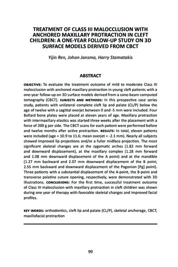
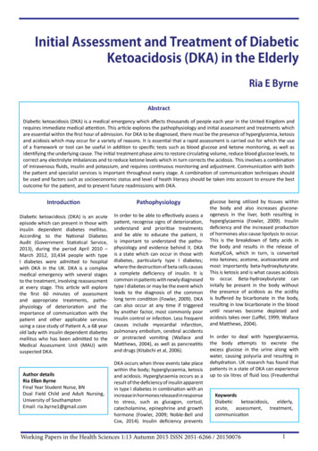
www.PDHcenter.comPDHonline Course M555www.PDHonline.org1. STEAM BOILER SYSTEMS1.1 STEAM BOILER SYSTEM DEFINED. A steam boiler is an enclosed vessel thatholds water and is heated by an external source that converts the water to steam. Allsteam boilers contain tubes that separate the water from the heat source. Steamboilers are described in this publication.1.1.1 TYPES OF STEAM BOILERS. Boilers are classified by two criteria: 1) operatingpressure (i.e., the amount of internal pressure generated by the steam that isproduced); and 2) the operational design (i.e., whether the water [water tube boiler] orthe heat source [fire tube boiler]) passes through the inside of the tubes of the boilervessel.1.1.1.1 PRESSURE CLASSIFICATION. A boiler that operates at pressures below 103kilopascals (15 pounds per square inch gauge) is defined as a low-pressure boiler. Aboiler operating pressure greater than 103 kilopascals (15 pounds per square inchgauge) is defined as high pressure. High-pressure boilers can operate at pressuresreaching thousands of kilopascals (thousands of pounds per square inch gauge).1.1.1.2 FIRE TUBE BOILERS. Fire tube boilers pass fire and hot combustion gasthrough the interior of the boiler tubes to heat the water that surrounds the tubes (seeFigure 1.1). This type of boiler design is commonly used for factory-assembled(package) boilers, which are low pressure.1.1.1.3 WATER TUBE BOILERS. Water tube boilers pass water through the boilertubes, with the fire and hot combustion gases contacting the exterior of the tubes (seeFigure 1.2). Water tube boilers are used in high-pressure and very-high-pressureapplications. Most military installations have a central boiler plant containing watertube boilers in addition to fire tube boilers that are located in, and serve, individualbuildings. 2015 J. Paul GuyerPage 3 of 76
www.PDHcenter.comPDHonline Course M555www.PDHonline.orgFigure 1.1Fire Tube Boiler 2015 J. Paul GuyerPage 4 of 76
www.PDHcenter.comPDHonline Course M555www.PDHonline.orgFigure 1.2. Water Tube BoilerFigure 1.2Water Tube Boiler1.1.1.4 BOILER CAPACITY RATING. Boiler capacity rating is given as units of eitherboiler horsepower, kilograms of steam per second (pounds per hour), or kilowatts(British thermal units [BTU] per hour), specifically: 1) one boiler horsepower unitreflects the energy to convert 15.7 kilograms (34.5 pounds) of water to steam from(and at) 100 oC at sea level, which is equivalent to 9.812 kilowatts (33,479 BTU perhour); 2) kilogram of steam produced per second (pound of steam produced perhour) represents the number of kilograms of water used each second (pound perhour) to produce the steam; and 3) kilowatts (3,413 BTUs per hour) reflect the energyneeded to evaporate the water (produce steam) each hour. The actual quantity ofsteam produced will vary depending on the boiler efficiency, boiler operatingpressure, and altitude with respect to sea level.1.1.2 COMPONENTS OF A STEAM BOILER SYSTEM. The functional componentsof steam boiler systems vary from one system to another based on a variety of design, 2015 J. Paul GuyerPage 5 of 76
www.PDHcenter.comPDHonline Course M555www.PDHonline.orgengineering and service requirements. The typical components that may be includedin a specific unit are illustrated in Figure 1.3 and are briefly described in paragraphs1.1.2.1 through 1.1.2.5.Figure 1.3Components of a Simple Steam Boiler System1.1.2.1 PRE-BOILER. The pre-boiler section of a steam boiler encompasses theboiler system’s structural components that hold, move, and treat the water before thewater enters the boiler. These pre-boiler system components include the integrated orsupplementary water pre-treatment equipment used to process the boiler makeupwater, the deaerator used to remove oxygen and other non-condensable gases, and 2015 J. Paul GuyerPage 6 of 76
www.PDHcenter.comPDHonline Course M555www.PDHonline.orgthe feedwater heaters and pumps. The pre-boiler section may include a storage tankfor the treated makeup water. The boiler feedwater is usually composed of themakeup water combined with the condensed steam (condensate) that is returned fromthe distribution system (called the condensate return). The feedwater, pre-heated ornot, then enters the deaerator, which is used to remove (deaerate) oxygen and othervolatile gases.1.1.2.2 AFTER-BOILER. The after-boiler, or post-boiler, section of the boiler systemencompasses all structural components of the boiler system that hold, move, andprocess the steam and water downstream from the actual boiler. The after-boilerincludes steam piping, heat exchangers, steam traps, condensate piping, turbines,process equipment, and superheaters.1.1.2.3 BOILER COMPONENTS. A fire tube boiler passes the hot combustion gasesthrough the tubes, which are surrounded by the water to be converted to steam. Awater tube boiler passes the hot combustion gases around the tubes, which containthe water to be converted to steam. In either type of boiler, the steam passes into asteam drum and then into the steam lines. The circulation of water in the water tubeboiler may be accomplished by heating only, through a process of “natural circulation,”which requires no external force or pumping. Alternatively, the water can be pumpedthrough the heating circuit of the boiler by a process referred to as “forced circulation.”Usually, a mud drum is provided at the lowest point in the water circulation section toallow the removal of any water-formed sludge. There will be at least two locations forthe removal of boiler water blowdown: 1) for surface blowdown, sometimes referred toas a skimmer, located just below the operating water level of the steam drum; and 2)one or more bottom blowdown locations at the mud drum.1.1.2.4 STEAM DRUM. The feedwater is added to the steam drum, where a mixtureof steam and water is produced and where the steam is separated from the water.This separation process usually includes using mechanical devices to assist inremoving any entrained boiler water from the steam. Chemicals used for internal 2015 J. Paul GuyerPage 7 of 76
www.PDHcenter.comPDHonline Course M555www.PDHonline.orgboiler water treatment may be added (fed) to the water in the steam drum. A processof either continuous or intermittent surface blowdown is used to maintain the TDS ofthe boiler water and achieve the optimal operating conditions in the boiler. In someboiler systems, the blowdown water will be discharged to a flash tank, where a lowerpressure steam is produced (possibly for use in the deaerator). Also, water fromcontinuous blowdown may be used to preheat the makeup water by means of a heatexchanger. Steam from the drum may be discharged directly to the steam header or,in some boilers, heated further in a superheater to generate superheated steam.1.1.2.5 STEAM HEADER. The steam generated by the boiler is discharged from thesteam drum to a header. The steam header feeds the steam to the steam distributionsystem. The steam is consumed by process equipment, lost through leaks, lost fromvalves, fittings, or steam traps, or condensed for return to the deaerator andsubsequently reused for additional steam production.1.1.3 MEASURING EQUIPMENT. To develop an appropriate water treatmentprogram for a steam boiler system, as well as to monitor the effectiveness of theongoing program, measure the quantities of steam, feedwater, blowdown, makeup,and condensate into and from the system. As a minimum, install a flow meter in themakeup water line. Installing flow meters on the feedwater line and in the steamheader is also advisable, but due to cost considerations this practice is usually limitedto large steam boilers. The rates and volumes for production of condensate andblowdown water can be calculated using the method described below.1.1.4 COMMON BOILER PROBLEMS. Common water-related problems inside theentire boiler system are corrosion, deposition, and carryover.1.1.4.1 CORROSION PROBLEMS. Corrosion problems are the result of the action ofoxygen and the effect of low or high pH on metal components, including the boilertubes and drum, which are constructed of carbon steel. Corrosion can also occur fromexcessive alkalinity of excessive pH of the boiler water. This caustic attack is most 2015 J. Paul GuyerPage 8 of 76
www.PDHcenter.comPDHonline Course M555www.PDHonline.orglikely to occur under scale or deposits, where very high local c oncentrations ofhydroxide can build or in zones where insufficient cooling flows fails to sufficientlyremove the heat input, leading to boiling, and thus steam blanketing occurs.”Corrosion can occur in the boiler, as well as in the pre-boiler and after-boiler sections,which can also be constructed of carbon steel. Corrosion can result in loss of metalvolume or in a reduction of the integrity of the metal, situations that can lead tostructural failure, particularly when metal loss is localized (see Figure 1.4). Corrosionis therefore also a safety concern. Corrosion in the steam lines, condensate lineslocated in the after-boiler section, and in the carbon steel piping can result in theproduction of system leaks leading to the loss of condensate, a s ituation whichincreases demands for energy, water, and chemicals.Figure 1.4Boiler Tube Oxygen Pitting1.1.4.2 DEPOSITION PROBLEMS. Deposition problems result from the precipitationof minerals dissolved in the feedwater, causing the formation of one or more types ofscale on boiler system components. Deposition can occur by other mechanisms whencorrosion products (rust) enter the boiler after being created in either the after-boiler orpre-boiler sections. These corrosion products can form iron-based scales. Using 2015 J. Paul GuyerPage 9 of 76
www.PDHcenter.comPDHonline Course M555www.PDHonline.orgcertain water treatment chemicals can also result in the formation of scale when thechemicals are not properly applied. All scales provide insulation to the transfer of heatbetween the water and the heated metal tubes. Scale can occur in any section of theboiler system, resulting in a reduced capacity for heat transfer. Due to the resultingreduced heat transfer from the fireside of the tube to the water, the metal tubesoperate at a higher temperature than if the scale were not providing insulation.Consequently, steam is produced inefficiently due to greater fuel demands, and fuelcosts are increased. The greater the thickness of scale, the greater the insulatingeffect, and the higher the temperature of the tubes (see Figure 1.6). At sufficientlyhigh metal temperatures, the tube can lose its tensile strength and rupture.Figure 1.5Scaled Boiler Tube 2015 J. Paul GuyerPage 10 of 76
www.PDHcenter.comPDHonline Course Deposit ThicknessFigure 1.6Impact of Scale on Heat TransferFigure 1.7Metal Fatigue on Boiler Tube 2015 J. Paul GuyerPage 11 of 76
www.PDHcenter.comPDHonline Course M555www.PDHonline.orgFigure 1.8Failed Boiler Tube1.1.4.3 CARRYOVER PROBLEMS. Carryover problems are caused by misting,foaming, priming, and silica carryover. Carryover is a process that results in impuresteam quality. Dissolved solids contained in the carryover material can contribute tocorrosion and deposition problems.1.1.5 CALCULATIONS. To understand and produce efficient boiler operations, boilercalculations are performed and the results applied correctly. Boiler calculations are themeans for providing information used to determine optimal blowdown rates and toassess condensate return. The greatest efficiency of boiler operations can beachieved by optimizing the COC by adjusting the amount of blowdown to give theproper volume of water. Efficient boiler operations recover and return as muchcondensate as possible. The material balance or mass balance of an operating boilersystem can be calculated from the results of water tests and the known (measured) 2015 J. Paul GuyerPage 12 of 76
www.PDHcenter.comPDHonline Course M555www.PDHonline.orgvalue of a single boiler operational parameter such as steam production, makeupwater usage, feedwater usage, or blowdown. Steam table data can be used with massbalance information to calculate energy input and energy output for the boiler system.Chemical feed rates can be used with mass balance information to develop anestimation tool for the annual consumption of water treatment chemicals. Familiaritywith these calculation procedures and their application to boiler system operationsassessment is required of any base or facility engineer or section supervisor. Thisknowledge is also useful for boiler operators.1.1.5.1 CYCLES OF CONCENTRATION (COC). COC in a steam boiler is a term thatrefers to the number of times the minerals in the feedwater have been concentrated inthe boiler by its operation. As boiler water is evaporated and steam is produced,minerals that were dissolved in the boiler water remain behind, increasing the mineralcontent of the remaining water. As steam is produced, additional mineral-ladenfeedwater enters the boiler, resulting in additional minerals being introduced into theboiler and increasing the amount present in the boiler. Mineral content in an operatingboiler water system can be limited only by blowdown.1.1.5.2 BLOWDOWN. Blowdown consists of draining some of the boiler water with itsaccumulated solids, and replacing it with treated feedwater before harmful levels ofsolids are reached. Dissolved solids tend to concentrate near the water surface in thesteam drum. Therefore, surface blowdown is most effective in reducing theconcentration of dissolved solids. Bottom blowdown is used to remove precipitatedsludge from the boiler mud drum. However, blowdown results in the loss of heatedwater and treatment chemicals. Economical operation requires careful control ofblowdown to maintain sage solids levels, while minimizing both heat and chemicaladditive losses.1.1.5.3 WATER BALANCE FOR FEEDWATER, EVAPORATION, ANDBLOWDOWN. The total volume of the water (feedwater) that is added to the boilermust equal the total volume of the water (steam plus boiler water blowdown) that is 2015 J. Paul GuyerPage 13 of 76
www.PDHcenter.comPDHonline Course M555www.PDHonline.orgremoved from the boiler. By convention, these water quantities are commonlyexpressed in kilograms per second (pounds per hour) in this equation for waterbalance:1.1.5.4 CALCULATION OF FEEDWATER AND BLOWDOWN WATER. Thefeedwater or blowdown water (or both) can be calculated in relation to the COC usingthese equations:1.1.5.5 RELATIONSHIP BETWEEN FEEDWATER, BLOWDOWN, STEAMGENERATION, AND COC. Using the terms defined above, the relationship betweenfeedwater, blowdown, steam generation, and COC is represented as: 2015 J. Paul GuyerPage 14 of 76
www.PDHcenter.comPDHonline Course M555www.PDHonline.org1.1.5.6 CALCULATING BLOWDOWN RATES. The blowdown water volume is rarelymeasured by a meter. As shown below, it can be calculated if any two of the followingparameters are known: 1) feedwater; 2) COC; or 3) steam generation (E). Steamvolume is usually measured in units of meters on large boilers. The COC can becalculated by measuring the conductivity or TDS in both the boiler water and thefeedwater. Note that the conductivity and quantity of TDS is the same for the boilerwater and the blowdown water.1.1.5.7 DETERMINING FEEDWATER AND BLOWDOWN RATES. The blowdowncalculations in paragraph 1.1.5.6 can be used to determine the feedwater rate in unitsof kilograms per hour (pounds per hour). Note that the term “feedwater” refers to waterthat is fed to the boiler and includes the makeup water plus the condensate return andsteam from the deaerator.EXAMPLE: 2015 J. Paul GuyerPage 15 of 76
www.PDHcenter.comPDHonline Course M555www.PDHonline.orga) A 1720-kilopascal (250-pound-per-square-inch-gauge) boiler operates at aconductivity level of 5000 µmhos. The boiler feedwater has a conductivity of 250µmhos. The COC calculation is:This is equivalent to 5.3 liters per second (5054 gallons per hour at 8.33pounds per gallon). This example is illustrated in Figure 1.9.Condensate Return (R)3.8 kg/s(30,316 lb/hr )Pegging SteamMakeup (M)1.5 kg/s(11,789 lb/hr )DearatorFeedwater (F)5.26 kg/s(42,105 lb/hr )Steam Lost (L)1.2 kg/s(9684 lb/hr )Steam Generated (E)5 kg/s(40,000 lb/hr )Steam BoilerBlowdown (B)0.26 kg/s(2105 lb/hr ) 2015 J. Paul GuyerPage 16 of 76
www.PDHcenter.comPDHonline Course M555www.PDHonline.orgFigure 1.9Simplified Boiler System Water Balance1.1.6 DETERMINING MAKEUP WATER AND CONDENSATE RETURN RATES.Makeup is the water from the external water treatment system added to the boilersystem upstream of the deaerator. The amount, expressed as either volume orpercentage, of makeup water required in a boiler is affected by blowdown, steamleaks, consumption of steam in process equipment, and loss of condensate by boilersystem leakage. In a “tight” boiler system, where steam is not lost in processequipment, about 5 to 10% makeup is expected. Water balance is affected bycondensate return; however, boilers that lose considerable condensate due to lossesof steam or condensate can approach a requirement for 100% makeup, which is avery inefficient and costly condition. The calculations below can be used fordetermining makeup water needs and condensate return rates.1.1.6.1 MAKEUP WATER RATE. Makeup is the difference between the volume ofcondensate return and the volume of feedwater.1.1.6.2 CONDENSATE RETURN RATE. Since the returned condensate usually doesnot contain any appreciable level of dissolved solids or conductivity, determination ofpercent makeup is calculated using the equation: 2015 J. Paul GuyerPage 17 of 76
www.PDHcenter.comPDHonline Course M555www.PDHonline.org1.1.6.3 DIFFERENCE BETWEEN AMOUNT OF STEAM PRODUCED ANDAMOUNT OF CONDENSATE. The difference between amount of steam producedand the amount of condensate returned represents the combined loss from thesystem of both steam and condensate. These losses may result from leakage ofsteam, consumption of steam by the process equipment, leakage of condensate, or 2015 J. Paul GuyerPage 18 of 76
www.PDHcenter.comPDHonline Course M555www.PDHonline.orgdeliberate discharge of contaminated condensate. The total water loss can becalculated:1.1.6.4 BASIS FOR EVALUATING BOILER SYSTEM EFFICIENCY. A good basis forevaluating boiler system efficiency can be developed by monitoring the system’s waterconductivity values, measuring the quantity of steam generated, and performing therequired calculations after a regularly scheduled interval of time. An increase in steamloss may indicate a new leak, a size increase in existing leaks, a new consumption ofsteam, or condensate losses. Additionally, calculations of boiler system efficiency canprovide a good basis for estimating savings in steam cost resulting from maintenanceefforts to reduce steam and condensate losses. 2015 J. Paul GuyerPage 19 of 76
www.PDHcenter.comPDHonline Course M555www.PDHonline.org2. BOILER WATER TREATMENT AND CONTROL. References to boiler watertreatment in the late nineteenth century relate that the process of removing the scalefrom a boiler required much less effort and time if the boiler operator had forgotten toremove cooked potatoes from the boiler water. It was determined that the starch inpotatoes causes a soft sludge, rather than a hard scale, to be formed, and this sludgewas easier to remove than hard scale. Other natural organics, including lignin andtannins from wood, plant matter, plant extracts, and even manure and coffee grounds,produced similar results. It was determined that addition of phosphate by itselfproduces a manageable sludge, although starch, lignins, and tannins have been usedto supplement the phosphate. Phosphate is still very commonly combined with otherwater treatment chemicals. Early use of alkaline materials included lime, soda ash,and caustic soda. Oxygen scavengers, such as sodium sulfite, were found to beeffective for preventing oxygen corrosion. Many of these materials are still used today.The wide range of water treatment chemicals that is currently available allows fordevelopment of a comprehensive approach to industrial boiler water treatment,including using specialty chemicals such as chelants, polymers, and amines.2.1 BOILER DEPOSIT FORMATION. Dissolved solids in boiler feed water becomemore concentrated in the boiler water as steam is generated. Some of the dissolvedsolids can come out of solution (precipitate) and form scale in the boiler tubes. Somedissolved solids can form sludge (mud) in the boiler and form adherent deposits onboiler tubes. These deposits reduce heat transfer.2.1.1 SCALE. Scale can occur in isolated spots due to water evaporation. When asteam bubble forms on a heated surface, a thin film of water situated between thebubble and the tube wall becomes more concentrated with the dissolved materials.This thin layer can be as much as 17 oC (30 oF) hotter than the average boiler watertemperature. These local conditions can cause precipitation of the dissolved solidsand local formation of scale. 2015 J. Paul GuyerPage 20 of 76
www.PDHcenter.comPDHonline Course M555www.PDHonline.orgLowHot WaterDissolved SolidsConcentrationGradientSteam BubbleTube WallHighHeated SurfaceFigure 2.1Localized Scale Formation Process2.1.1.1 Sludge Deposits. Sludge deposits can form when the precipitated materials inthe boiler water stick to the boiler tubes due to their hot surfaces as a result of thesame phenomenon described in paragraph 2.1.1. Scale and sludge often formtogether.2.1.1.2 Dissolved Solid Materials. Some dissolved solid materials become lesssoluble as the water temperature increases. This situation occurs with most of thesalts that constitute calcium and magnesium hardness (CaCO 3, CaSO4, MgCO3,Mg[OH]2). As a result of this property, these materials tend to form scale in the hotterareas of the boiler because they remain soluble in the cooler areas of the boiler. Byusing an appropriate form of water treatment, these scaling agents can be removedfrom the boiler system water either before they enter the boiler (external treatment) orafter (internal treatment), although it is often best to remove the dissolved magnesiumand calcium minerals (hardness) before they enter the boiler (see paragraph 2-2).With the proper chemical treatment, they can be effectively controlled and treatedinternally in the boiler.2.2 COMMON SCALE FOUND IN BOILERS. The most common scale materialsconsist of calcium and magnesium salts and iron oxide. Calcium and magnesium salt 2015 J. Paul GuyerPage 21 of 76
www.PDHcenter.comPDHonline Course M555www.PDHonline.orgdeposits are white or off-white. Iron oxide scales are red or black deposits. The type ofscale can be identified accurately by deposit analysis. It is common to have more thanone type of scale in boiler deposits.2.2.1 CALCIUM CARBONATE. Calcium carbonate scale is white or off-white in colorand is formed by the breakdown of calcium bicarbonate with heat. Calcium carbonatescale is formed in both untreated boilers and improperly treated boilers. A drop of adilute acid solution on the deposit will cause bubbling on the calcium carbonate scalearea as a result of the release of carbon dioxide. This procedure can be used toidentify this type of scale. Calcium carbonate scale can result when there is calciumhardness in the boiler feedwater due to improper softener operation and when there isan inadequate level of sludge or scale conditioner or dispersant.2.2.2 CALCIUM SULFATE. Calcium sulfate (gypsum) is off-white or tan in color and isformed in boilers that are using water of high hardness and low alkalinity withoutproper treatment. Addition of a strong acid will dissolve the calcium sulfate scale withno gas bubble formation or release of carbon dioxide. Calcium sulfate is much lesscommon than calcium carbonate, but it can form when there is calcium hardness inthe boiler feedwater due to improper softener operation and when there is aninadequate level of sludge or scale conditioner or dispersant.2.2.3 CALCIUM PHOSPHATE. Calcium phosphate is formed when the dissolvedcalcium in the feedwater reacts with phosphate treatment chemicals added to theboiler water. With proper treatment controls, calcium phosphate forms a sludge thatwill be removed in the blowdown. However, calcium phosphate can deposit as scale ifthe pH of the boiler water is below 11.0 and if a sludge conditioner is not used.Addition of a strong acid will dissolve this scale fairly easily with no gas bubbleformation.2.2.4 MAGNESIUM PHOSPHATE. Magnesium phosphate scale is an off-whitedeposit formed by the reaction of magnesium salts from the feedwater with the 2015 J. Paul GuyerPage 22 of 76
www.PDHcenter.comPDHonline Course M555www.PDHonline.orgphosphate used in the boiler water treatment. It will form only if both the hydroxidecontent and silica content of the boiler water are low. Addition of a strong acid willdissolve this scale fairly readily with no gas bubble formation.2.2.5 MAGNESIUM SILICATE. Magnesium silicate scale, an off-white deposit, isformed from the magnesium and silica in the feedwater when the pH is above 11.0and the silica level is more than half that of the phosphate level in the boiler water.Normally, it forms as a sludge that will be removed in the blowdown, but it may formscale deposits on tubes if a sludge conditioner is not present. Most acids will notremove this deposit. Caustic or special chemicals are needed to remove themagnesium sulfate scale.2.2.6 IRON OXIDE AND IRON HYDROXIDE. Iron oxide scales and iron hydroxidescales are red/black deposits that are formed when the iron salts dissolved in thefeedwater react with hydroxide found in the boiler water. Usually, the dissolved iron isintroduced into the system from the condensate return due to corrosion. Iron oxidecan be deposited as a scale on the boiler tubes if the proper type of sludgeconditioner is not present. With proper water treatment, this deposit should form assludge, rather than scale, and can be removed by blowdown. The presence of ironoxide on the internal boiler surfaces can be caused by oxygen corrosion of the boilermetal.2.3 EXTERNAL BOILER WATER TREATMENT. The strategy for external treatmentis to remove unwanted impurities in the makeup water before they can enter theboiler. Proper external treatment can eliminate, or at least minimize, scale- andcorrosion-forming conditions and minimize the internal water treatment required toprotect the boiler system components.2.3.1 External Water Treatment for High-Pressure Boilers. The higher thepressure of the boiler, the greater the need for high-purity feedwater. A 5-kilogrampersecond (40,000-pound-per-hour) water tube boiler operating at 6205 kilopascals 2015 J. Paul GuyerPage 23 of 76
www.PDHcenter.comPDHonline Course M555www.PDHonline.org(900 pounds per square inch gauge) requires deionized feedwater. Externaltreatment options include RO followed by demineralization.2.3.2 External Treatment for Low-Pressure Boilers. Low-pressure boilers canoperate with simple external treatment or sometimes no external treatment at all. A0.44-kilogram-per-second (3450-pound-per-hour) (100 horsepower) fire tube boileroperating at less than 103 kilopascals (15 pounds per square inch gauge) mayrequire using only a sodium zeolite softener for water treatment. A small heatingboiler that is returning over 99% of the condensate may not require any externaltreatment, particularly if the makeup water is low in hardness and the condensate isnot contaminated.2.4 INTERNAL TREATMENT OF BOILER WATER. Internal treatment of boiler wateris a process of adding chemicals to the boiler to control deposition and corrosion.Internal water treatment, together with proper blowdown control, controls the waterimpurities that have not been removed or reduced through external treatment.2.4.1 PREVENTING SCALE FORMATION. Internal boiler water treatment for scaleprevention can be performed using either a solubilizing chemical treatment program ora precipitating chemical treatment program. The solubilizing treatment program useschemicals designed to keep scale-causing materials with hardness (mineral ions) insolution, whereas the precipitating treatment program uses chemicals designed toreact with hardness-causing materials and precipitate them as a sludge that will notadhere to tube surfaces. Both the solubilizing approach and the precipitating approachrequire good blowdown control to keep hardness and sludge levels within chemicalperformance capabilities.2.4.1.1 LOW-PRESSURE BOILERS. Low-pressure steam boiler systems (103kilopascals [15 pounds per square inch gauge] and less) that use little or no makeupor blowdown are usually not chemically treated for scale control because, due to lowmakeup water demands, there is no continuous
continuous blowdown may be used to preheat the makeup water by means of a heat exchanger. Steam from the drum may be discharged directly to the steam header or, in some boilers, heated further in a superheater to generate superheated steam. 1.1.2.5 STEAM HEADER. The steam generated by