Transcription
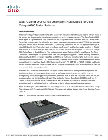
Data SheetCisco Catalyst 2950 Series Intelligent Ethernet Switchesfor Metro Access (Enhanced Image)Product OverviewThe Cisco Catalyst 2950 Series IntelligentEthernet switches is an affordable line of Cisco Catalyst 2950G-12 Switch—12 10/100 ports and 2 GBIC ports Cisco Catalyst 2950T-24 Switch—fixed-configuration Fast Ethernet and24 10/100 ports and 2 fixed 10/100/Gigabit Ethernet switches that extend1000BaseT uplink portsintelligence to the metro access edge, Cisco Catalyst 2950C-24 Switch—enabling service breadth, availability,24 10/100 ports and 2 fixed 100BaseFXsecurity, and manageability. Keyuplink portscomponents of the Cisco Metro Ethernet Catalyst 2950ST-24-LRE—24 LRE andSwitching portfolio, these switches are ideal2 Gigabit Ethernet ports (user can selectfor service providers looking to delivereither 10BaseT/100BaseTX/1000BaseTprofitable Ethernet services to theEthernet Ports or Small Form Factorresidential and small-office, home-officePluggable (SFP) Transceivers)(SOHO) market. Featuring advanced rate Catalyst 2950ST-8-LRE—8 LRE and 2limiting, voice virtual LAN (VLAN)Gigabit Ethernet ports (user can selectsupport, and multicast management, theseeither 10BaseT/100BaseTX/1000BaseTswitches enable a variety of residentialEthernet Ports or Small Form Factormetro services such as Internet access, voicePluggable (SFP) Transceivers)over IP (VoIP), and broadcast video.The two built-in Gigabit Ethernet ports onThe Cisco Catalyst 2950 Series Intelligentthe Cisco Catalyst 2950G-12, 2950G-24,Ethernet switches consists of the followingand 2950G-48 accommodate a range ofdevices—which are only available with theGBIC transceivers, including the CiscoEnhanced Image (EI) software for the CiscoCourse Wave Division MultiplexingCatalyst 2950 Series:(CWDM) GBIC Solution, Cisco Cisco Catalyst 2950G-48 Switch—GigaStack GBIC, 1000BaseSX,48 10/100 ports and 2 gigabit interface1000BaseLX/LH, 1000BaseZX andconverter (GBIC)-based Gigabit1000BaseT GBICs. The dual GBIC-basedEthernet portsGigabit Ethernet implementation provides Cisco Catalyst 2950G-24 Switch—24 10/100 ports and 2 GBIC ports Cisco Catalyst 2950G-24-DCcustomers with tremendous deploymentflexibility— allowing them increasedavailability with the redundant uplinks.Switch—24 10/100 ports, 2 GBIC ports,High levels of resiliency can also beand DC powerimplemented by deploying dual redundantGigabit Ethernet uplinks, UplinkFast andCisco Systems, Inc.All contents are Copyright 1992–2002 Cisco Systems, Inc. All rights reserved. Important Notices and Privacy Statement.Page 1 of 17
Per-VLAN Spanning Tree Plus (PVST ) for uplink load balancing. This Gigabit Ethernet flexibility makes the CiscoCatalyst 2950 Series switches an ideal metro access edge complement to the Cisco 7600 Series Internet Router andCisco Catalyst 6500 Series of metro Ethernet switches.Intelligence at the Metro Access Edge: Enabling Profitable Ethernet ServicesService providers that address the residential and SOHO market face the continual challenge of offering compellingvalue-added services.Although alternative broadband technologies such as DSL can offer bandwidth at speeds ranging up to 1.5 Mbps,the monthly subscriber fees for such speeds can be out of reach for most users. As a result, compelling high-qualityservices such as high-speed Internet access, VoIP, or broadcast video are often not viable propositions over thesetechnologies. However, in the metro, service providers are discovering that high-performance, Ethernet access overfiber-optic networks can easily provide cost-effective bandwidth of 10 to 100 Mbps. By taking advantage of thesimplicity and cost benefits of Ethernet, revenue growth via voice, video, and data services becomes a reality. Whenconsidering the deployment of Ethernet services, service providers must consider the following issues: Building cost-effective, highly available, scalable metro Ethernet networks Providing profitable new services while reducing operational and capital costs Having the network flexibility to move up market to enterprise and small and medium- sized business servicesThese issues are especially relevant at the metro access edge. As service providers look to provide profitable Ethernetservices such as high-speed Internet access, voice, and video, Cisco intelligent functionality such as advanced qualityof service (QoS), granular rate limiting, and multicast management are essential in the provider’s customer-locatedequipment. In addition, availability and security concerns at the access edge are addressed with intelligent featuressuch as subsecond Spanning Tree Protocol (STP) convergence and 802.1x support. With Cisco Catalyst 2950 SeriesIntelligent Ethernet switches, Cisco delivers the ideal balance of affordability and intelligence, enabling profitableEthernet service breadth, availability, security and manageability.Most important, the Cisco Catalyst 2950 Series is a key component of the Cisco Metro Ethernet Switching portfolio.As such, service providers are assured that they can offer a range of residential and commercial services over the samenetwork. For regional metro, metro aggregation, and metro access, Cisco Metro Ethernet Switching enables serviceproviders to deliver profitable, comprehensive Ethernet services. With the effective integration of existing WANservices such as Frame Relay and ATM, Cisco Metro Ethernet Switching offers an unmatched breadth of servicedelivery mechanisms. Cisco also helps service providers minimize total cost of ownership for new services with itsextensive automated operations support. Through technology leadership, financial stability, and a commitment tocustomer support, Cisco ensures service success from “start to scale.”Service Breadth Through Advanced Quality of Service, Rate Limiting, and Voice/Multicast FeaturesTo achieve profitability, service providers that serve the residential and SOHO markets must offer value-addedservices such as voice and video in addition to basic high-speed Internet connectivity to increase revenue persubscriber. But these services are compelling only when service quality matches that of competing voice andvideo offerings.Cisco Systems, Inc.All contents are Copyright 1992–2002 Cisco Systems, Inc. All rights reserved. Important Notices and Privacy Statement.Page 2 of 17
The Cisco Catalyst 2950 Series offers superior and highly granular QoS to ensure that network traffic is classifiedand prioritized, and that congestion is avoided in the best possible manner. The Cisco Catalyst 2950 Series canclassify, reclassify, police (determine if the packet is in or out of predetermined profiles and affect actions on thepacket), and mark or drop the incoming packets before the packet is placed in the shared buffer. Packet classificationallows the network elements to discriminate between various traffic flows and enforce policies based on Layer 2 andLayer 3 QoS fields.To implement QoS, first, the Cisco Catalyst 2950 Series switches identify traffic flows, or packet groups, and classifyor reclassify these groups using either the Differentiated Services Code Point (DSCP) field or the 802.1pclass-of-service (CoS) field, or both. Classification and reclassification can be based on criteria as specific as thesource/destination IP address, source/destination Media Access Control (MAC) address, or the Layer 4 TransmissionControl Protocol/User Datagram Protocol (TCP/UDP) port. At the ingress, the Cisco Catalyst 2950 Series can alsoperform policing and marking of the packet.After the packet goes through classification, policing, and marking, it is then assigned to the appropriate queue beforeexiting the switch. The Cisco Catalyst 2950 Series supports four egress (outgoing port) queues per port, which allowsthe service provider to be more discriminating and specific in assigning priorities for the various applications. At theegress, the switch performs Weighted Round Robin (WRR) or strict priority scheduling to determine the order inwhich the queues are processed. The WRR queuing algorithm ensures that the lower-priority packets are not entirelystarved for bandwidth and are serviced without compromising the priority settings administered by the networkmanager. Strict priority scheduling ensures that the highest-priority packets are always serviced first, ahead of allother traffic.In terms of rate limiting, the Cisco Catalyst 2950 Series is capable of allocating bandwidth based on several criteria,including MAC source address, MAC destination address, IP source address, IP destination address, and TCP/UDPport number. Bandwidth allocation is essential in network environments requiring service-level agreements (SLAs),or when it is necessary for the network manager to control the bandwidth given to certain subscribers. The CiscoCatalyst 2950 Series supports up to 6 policers per Fast Ethernet port and up to 60 policers on a Gigabit Ethernetport. Traffic policing can be done in 1-Mbps increments on Fast Ethernet ports and 8-Mbps increments on GigabitEthernet ports, giving the network manager very granular control of network bandwidth.In addition, the Cisco Catalyst 2950 Series provides key voice and video service features with voice VLAN (auxiliaryVLAN) for VoIP services and hardware-based Internet Group Management Protocol (IGMP) snooping, allowing theswitch to “listen in” on the IGMP conversation between hosts and routers. When a switch hears an IGMP joinrequest from a host for a given multicast group, the switch adds the host port number to the Group DestinationAddress (GDA) list for that group. And, when the switch hears an IGMP leave request, it removes the host port fromthe list. Together with the superior QoS and rate-limiting features mentioned previously, service providers can builda flexible network with the Cisco Catalyst 2950 Series to provide voice, video, and data services all in one networkarchitecture.Service Availability through Resiliency Enhancements and Network RedundancyThe Cisco Catalyst 2950 Series provides a rich set of resiliency enhancement features to ensure quick failoverrecovery and create a high-availability network. The IEEE 802.1w Rapid Spanning Tree standard allows the serviceprovider to achieve subsecond spanning tree convergence times to maximize network stability and reliability. TheCisco Systems, Inc.All contents are Copyright 1992–2002 Cisco Systems, Inc. All rights reserved. Important Notices and Privacy Statement.Page 3 of 17
IEEE 802.1s Multiple Spanning Tree standard can be deployed in conjunction with 802.1w to improve the scalabilityof the STP by grouping VLANs into spanning tree instances, as well as to provide backward compatibility to devicesrunning the 802.1D STP.In addition, service providers can enable Bridge Protocol Data Unit (BPDU) guard and Spanning Tree Root Guard(STRG) to enhance the reliability of their networks. BPDU guard allows the service provider to shut down STPPortFast-enabled interfaces to avoid receiving BPDUs from their customers’ networks. STRG prevents customerdevices outside of the service provider’s network from becoming STP root nodes.The Cisco Catalyst 2950 Series enables the service provider to construct a highly redundant network. PVST allowsthe service provider to implement Layer 2 load-sharing on redundant links, efficiently utilizing the extra capacityinherent in a redundant design. Service providers can also utilize Cisco EtherChannel technology to aggregate upto 4 Gbps through Gigabit EtherChannel technology and up to 1.6 Gbps through Fast EtherChannel technology. TheCisco EtherChannel technology enhances fault tolerance and offers higher-speed aggregated bandwidth betweenswitches and to routers.In addition to resiliency and network redundancy advantages, the Cisco Catalyst 2950 Series enables metro networkscalability at the access edge through its support of Cisco CWDM GBIC Solution. This solution allows serviceproviders to scale their bandwidth without deploying additional fiber. The service provider can scale up to eightgigabits of bandwidth on a pair of single-mode fibers at distances up to 120 km. With the support for Cisco CWDMGBICs on the Cisco Catalyst 2950 Series, service providers can aggregate multiple Cisco Catalyst 2950 Seriesswitches to easily upgrade network bandwidth with existing fiber infrastructure.Metro network scalability is also enhanced by the Cisco Catalyst 2950 Series support of 4096 VLAN IDs and 256active VLANs per switch.Service Security Through Cisco Access Control Parameters and Enhanced SecurityFeaturesThe Cisco Catalyst 2950 Series offers enhanced data security through the use of access control parameters (ACPs).By denying packets based on source and destination MAC addresses, IP addresses, or TCP/UDP ports, users can berestricted from sensitive portions of the network. Also, because all ACP lookups are done in hardware, forwardingperformance is not compromised when implementing ACP-based security in the network.Service providers can also implement higher levels of data security by supporting private VLAN edge. This featureprovides security and isolation between ports on a switch, ensuring that traffic travels directly from its entry pointto the aggregation device through a virtual path and cannot be directed to a different port. Local Proxy AddressResolution Protocol (ARP) works in conjunction with private VLAN edge to minimize broadcasts and maximizeavailable bandwidth.With the Cisco Catalyst 2950 Series, service providers can implement high levels of console security. Multilevel accesssecurity on the switch console and the Web-based management interface prevents unauthorized users from accessingor altering switch configuration. Terminal Access Controller Access Control System (TACACS ) authenticationenables centralized access control of the switch and restricts unauthorized users from altering the configuration.Service providers are also able to enhance their network security by adding 802.1x port-based authentication forauthenticating individual customers, and port security with MAC address aging for limiting the concurrent MACaddresses allowed per port.Cisco Systems, Inc.All contents are Copyright 1992–2002 Cisco Systems, Inc. All rights reserved. Important Notices and Privacy Statement.Page 4 of 17
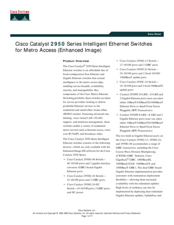
Service Management Through Cisco IE 2100 Series and SNMPThe Cisco Catalyst 2950 Series provides outstanding service management capabilities via Cisco IE 2100 SeriesIntelligence Engine support and Simple Network Management Protocol (SNMP). Service providers will be able tointegrate the Cisco Catalyst 2950 Series seamlessly into their operations support systems (OSSs) and enable improvedflow-through provisioning.The Cisco IE 2100 Series network device allows service providers to effectively manage a network of Cisco IOS devices, including the Cisco Catalyst 2950 Series. It is a completely self-contained unit that includes a task-orientedWeb graphical user interface (GUI), a programmable extensible markup language (XML) interface, configurationtemplate management, and an embedded repository. Network operators can use the Web GUI to quickly turn existingCisco IOS command-line interface (CLI) configuration files into reusable templates. The Cisco IE 2100 Seriessupports easy integration into existing customer OSS/business support system (BSS) and provisioning systems via itsexternal repository support and the event-based Cisco IOS XML interface that effectively “workflow-enables” Ciscodevice deployment.Service providers also can manage the Cisco Catalyst 2950 Series using SNMP version 2 and version 3, and the Telnetinterface for comprehensive in-band management. A CLI-based management console provides detailed out-of-bandmanagement.A comprehensive set of Management Information Bases (MIBs) is provided for the service provider to collect trafficinformation on the Cisco Catalyst 2950 Series for various billing methods.Figure 1Cisco Catalyst 2950 Series Intelligent Ethernet SwitchesCisco Systems, Inc.All contents are Copyright 1992–2002 Cisco Systems, Inc. All rights reserved. Important Notices and Privacy Statement.Page 5 of 17
Product Features and BenefitsFeatureBenefitService BreadthAdvanced QoS This feature enables end-to-end QoS in the network by extending the QoStrust boundary to the edge of the network. The switches support configuring QoS ACPs on all ports to ensure properpolicing and marking on a per-packet basis using ACPs. Up to four ACPs perswitch are supported in configuring either QoS ACPs or security filters.QoS Classification Support at Ingress The switches support QoS classification of incoming packets for QoS flowsbased on Layer 2, Layer 3, and Layer 4 fields. The following Layer 2 fields or a combination can be used for classifyingincoming packets to define QoS flows: source MAC address, destinationMAC address, 16-bit Ethertype. The following Layer 3 and 4 fields or a combination can be used to classifyincoming packets to define QoS flows: source IP address, destination IPaddress, TCP source or destination port number, UDP source or destinationport number.QoS Metering/Policing at Ingress Support for metering/policing of incoming packets restricts incoming trafficflows to a certain rate. The switches support up to 6 policers per Fast Ethernet port, and 60 policerson a Gigabit Ethernet port. The switches offer granularity of traffic flows at 1 Mbps on Fast Ethernetports, and 8 Mbps on Gigabit Ethernet ports.QoS Marking at Ingress The switches support marking/remarking packets based on state of policers/meters. The switches support marking/remarking based on the following mappings:from DSCP to 802.1p, and 802.1p to DSCP. The switches support 14 well-known and widely used DSCP values. The switches support classifying or reclassifying packets based on defaultDSCP per port. The switches support classifying or reclassifying frames based on default802.1p value per port. The switches support 802.1p override at ingress.Cisco Systems, Inc.All contents are Copyright 1992–2002 Cisco Systems, Inc. All rights reserved. Important Notices and Privacy Statement.Page 6 of 17
FeatureBenefitService BreadthAdvanced QoS(continued)QoS Scheduling Support at Egress Four queues per egress port are supported in hardware. The WRR queuing algorithm ensures that low-priority queues are notstarved. Strict-priority queue configuration ensures that time-sensitive applicationssuch as voice always follow an expedited path through the switch fabric.Granular rate limiting The switch supports up to 6 policers per Fast Ethernet port and up to 60policers on a Gigabit Ethernet port. The switch offers granularity of traffic flows at 1 Mbps on Fast Ethernet portsand 8 Mbps on Gigabit Ethernet ports. The switch offers the ability to limit data flows based on MAC source/destination address, IP source/destination address, TCP/UDP port numbers,or any combination of these fields. The switch offers the ability to manage data flows asynchronously upstreamand downstream from the end station or on the uplink.Voice and video services The IGMP snooping feature allows the switch to “listen in” on the IGMPconversation between hosts and routers. When a switch hears an IGMP joinrequest from a host for a given multicast group, the switch adds the hostport number to the GDA list for that group. And, when the switch hears anIGMP leave request, it removes the host port from the list. Multicast VLAN registration (MVR) continuously sends multicast streams ina multicast VLAN while isolating the streams from subscriber VLANs forbandwidth and security reasons. IGMP filtering provides the control of the set of multicast groups to which auser on a switch port can belong. Voice VLAN (auxiliary VLAN) support for VoIP application allows thecreationResiliency and reliability IEEE 802.1w Rapid Spanning Tree Protocol (RSTP) takes advantage ofpoint-to-point wiring and provides rapid convergence of the spanning treeindependent of spanning-tree timers. Reconfiguration of the spanning treecan occur in less than one second, a feature that is critical for networkscarrying delay-sensitive traffic such as voice and video. IEEE 802.1s Multiple Spanning Tree (MSTP), which uses RSTP for rapidconvergence, enables VLANs to be grouped into a spanning-tree instance,with each instance having a spanning-tree topology independent of otherspanning-tree instances. This architecture provides for multiple forwardingpaths for data traffic, enables load balancing, and reduces the number ofspanning-tree instances required to support a large number of VLANs. Cisco UplinkFast/BackboneFast technologies ensure quick failover recovery,enhancing overall network stability and reliability.Cisco Systems, Inc.All contents are Copyright 1992–2002 Cisco Systems, Inc. All rights reserved. Important Notices and Privacy Statement.Page 7 of 17
FeatureBenefitService BreadthResiliency and reliability(continued) Cisco CrossStack UplinkFast (CSUF) technology provides increasedredundancy and network resiliency through fast spanning-tree convergence(less than two seconds) across a stack of switches using Cisco GigaStackGBICs in an independent stack backplane cascaded configuration. Redundant stacking connections provide support for a redundant loopbackconnection for top and bottom switches in an independent stack backplanecascaded configuration. BPDU guard shuts down STP PortFast-enabled interfaces when BPDUs arereceived to avoid accidental spanning tree topology changes. STRG prevents edge devices not in the network administrator's control frombecoming STP root nodes. Command switch redundancy enabled in the Cisco Cluster ManagementSuite (CMS) Software allows customers to designate a backup commandswitch that takes over cluster management functions if the primarycommand switch fails. Unidirectional link detection (UDLD) detects and disables unidirectionallinks on fiber-optic interfaces caused by incorrect fiber-optic wiring or portfaults. Aggressive UDLD allows precautionary disabling of port onbidirectional links. Per-port broadcast, multicast, and unicast storm control prevents faulty endstations from degrading overall systems performance. Support for Cisco’s optional RPS 300 Redundant Power System providessuperior internal power source redundancy for up to six Cisco networkingdevices, resulting in improved fault tolerance and network uptime.Redundancy Bandwidth aggregation up to 4 Gbps through Cisco Gigabit EtherChanneltechnology and up to 1.6 Gbps through Cisco Fast EtherChannel technologyenhances fault tolerance and offers higher-speed aggregated bandwidthbetween switches, to routers and individual servers. IEEE 802.1D STP support for redundant backbone connections and loop-freenetworks simplifies network configuration and improves fault tolerance. PVST allows for Layer 2 load sharing on redundant links to efficientlyutilize the extra capacity inherent in a redundant design. VLAN Trunking Protocol (VTP) pruning limits bandwidth consumption onVTP trunks by flooding broadcast traffic only on trunk links required to reachthe destination devices.Scalability CWDM GBIC solution support allows for the scaling of bandwidth withoutdeploying additional fiber. It provides scalability of up to eight Gigabits ofbandwidth on a pair of single-mode fibers to reach distances up to 100–120km. Support for up to 4096 VLAN Ids with 250 active VLANs per switch, and upto 64 spanning tree instances per switch.Cisco Systems, Inc.All contents are Copyright 1992–2002 Cisco Systems, Inc. All rights reserved. Important Notices and Privacy Statement.Page 8 of 17
FeatureBenefitService SecurityNetwork-wide security features Filtering of incoming traffic flows based on Layer 2, Layer 3, or Layer 4 ACPsprevents unauthorized data flows. Up to four ACPs are supported inconfiguring either QoS or security filters.– The following Layer 2 ACPs or a combination can be used for securityclassification of incoming packets: source MAC address, destination MACaddress, and 16-bit Ethertype.– The following Layer 3 and Layer 4 fields or a combination can be used forsecurity classification of incoming packets: source IP address, destinationIP address, TCP source or destination port number, UDP source, ordestination port number. Private VLAN edge provides security and isolation between ports on aswitch, ensuring that voice traffic travels directly from its entry point to theaggregation device through a virtual path and cannot be directed to adifferent port. IEEE 802.1x for dynamic port-based security. Support for “secure ports” prevents unauthorized stations from accessingthe switch by restricting the number of concurrent MAC addresses allowedto access the port. Up to 132 addresses can be configured per port. STRG prevents edge devices not in the network administrator's control frombecoming STP root nodes. The STP PortFast/ BPDU guard feature disables access ports with STPPortFast enabled upon reception of a BPDU, and increases networkreliability, manageability, and security. Multilevel security on console access prevents unauthorized users fromaltering the switch configuration. TACACS and Remote Access Dial-In User Service (RADIUS) authenticationenables centralized control of the switch and restricts unauthorized usersfrom altering the configuration.Service ManagementSuperior manageability Cisco IE 2100 support for flow- through provisioning and integration withOSS applications via programmatical interfaces. SNMP v1, v2c, v3, and Telnet interface support delivers comprehensivein-band management, and a CLI-based management console providesdetailed out-of-band management. Manageable through CiscoWorks network management software on aper-port and per-switch basis providing a common management interfacefor Cisco routers, switches, and hubs. Comprehensive MIBs enable the service provider to collect trafficinformation on the Cisco Catalyst 2950 Series for various billing methods.Cisco Systems, Inc.All contents are Copyright 1992–2002 Cisco Systems, Inc. All rights reserved. Important Notices and Privacy Statement.Page 9 of 17
FeatureBenefitService ManagementSuperior manageability(continued) An embedded Remote Monitoring (RMON) software agent supports fourRMON groups (history, statistics, alarms, and events) for enhanced trafficmanagement, monitoring, and analysis. The switch supports all nine RMON groups through the use of a CiscoSwitchProbe Analyzer (Switched Port Analyzer [SPAN]) port, permittingtraffic monitoring of a single port, a group of ports, or the entire switch froma single network analyzer or RMON probe. RSPAN (Remote SPAN) allows network administrators to remotely monitorports in a Layer 2 switch network from any other switch in the samenetwork. The Domain Name System (DNS) provides IP address resolution withuser-defined device names. Trivial File Transfer Protocol (TFTP) reduces the cost of administeringsoftware upgrades by downloading from a centralized location. Network Timing Protocol (NTP) provides an accurate and consistenttimestamp to all switches within the intranet. Multifunction LEDs per port for port status, half-duplex/full-duplex, 10BaseT/100BaseTX/1000BaseT indication, as well as switch-level status LEDs forsystem, redundant power supply, and bandwidth utilization provide acomprehensive and convenient visual management system.Ease of use and ease of deployment Autoconfiguration eases deployment of switches in the network byautomatically configuring multiple switches across a network via a bootserver. Autosensing on each non-GBIC port detects the speed of the attached deviceand automatically configures the port for 10-, 100-, or 1000-Mbps operation,easing the deployment of the switch in mixed 10, 100, and 1000BaseTenvironments. Autonegotiating on all ports automatically selects half- or full-duplextransmission mode to optimize bandwidth. Cisco Discovery Protocol Versions 1 and 2 enable a CiscoWorks networkmanagement station to automatically discover the switch in a networktopology. Cisco VTP supports dynamic VLANs and dynamic trunk configuration acrossall switches. Support for dynamic VLAN assignment through implementation of VLANMembership Policy Server (VMPS) client functionality provides flexibility inassigning ports to VLANs. Dynamic Trunking Protocol (DTP) enables dynamic trunk configurationacross all ports in the switch. Port Aggregation Protocol (PAgP) automates the creation of Cisco FastEtherChannel or Gigabit EtherChannel groups, enabling linking to anotherswitch, router, or server. IEEE 802.3z-compliant 1000BaseSX, 1000BaseLX/LH, 1000BaseZX, and1000BaseT physical interface support through a field-replaceable GBICmodule provides customers unprecedented flexibility in switch deployment.Cisco Systems, Inc.All contents are Copyright 1992–2002 Cisco Systems, Inc. All rights reserved. Important Notices and Privacy Statement.Page 10 of 17
FeatureBenefitService ManagementEase of use and ease of deployment(continued) The default configuration stored in Flash memory ensures that the switchcan be quickly connected to the network and can pass traffic with minimaluser intervention. The switches support nonstandard Ethernet frame sizes (mini-giants) up to1542 bytes (configurations with GBIC ports only).Product Specifications(See separate Cisco Catalyst 2950 LRE data sheet for Catalyst 2950ST-24-LRE and Catalyst 2950ST-8-LRE e Management 13.6-Gbps switching fabric6.8-Gbps maximum forwarding bandwidthForwarding rates based on 64-byte packetsCisco Catalyst 2950G-48: 10.1-Mpps wire-speed forwarding rateCisco Catalyst 2950G-24 and 2950G-24-DC: 6.6-Mpps wire-speedforwarding rateCisco Catalyst 2950G-12: 4.8-Mpps wire-speed forwarding rateCisco Catalyst 2950T-24: 6.6-Mpps wire-speed forwarding rateCisco Catalyst 2950C-24: 3.9-Mpps wire-
running the 802.1D STP. In addition, service providers can enable Bridge Protocol Data Unit (BPDU) guard and Spanning Tree Root Guard (STRG) to enhance the reliability of their networks. BPDU guard allows the service provider to shut down STP PortFast-enabled interfaces to avoid receivin