Transcription
ICND2 -200-101 Study Guide (CCNA)SECTION I (21%) – LAN Switching Technologies1.1 – Identify Enhanced Switching Technologiesa. Rapid Spanning Tree Protocol (RSTP); IEEE 802.1w1) This is ability to by-pass the full 50sec 4-state STP convergence processa) RSTP States:1. Discarding – initial state; no traffic passes through Interface in or out, except STP msgsi. NOTE: This State is different than in (default) PVST, which is called BLOCKINGii. This state also refers to an Interface that is admin disabled (is disabled state for PVST)2. Learning – Switch does not fwd Frames; begins learning MAC of recv’d Frames3. Forwarding – final state; traffic passes/fwd’s through Interface normally2) STP goes from Discard Forward convergence in a few secs (50secs for PVST)3) NOTE: legacy STP IEEE 802.1d4) Other Port Types for RSTP:a) Alternate – port that will take over for the Root Port (RP) if RP link failsb) Backup – port that will take over for the Designated Port (DP) if the DP link fails; usuallyconnects to a Hubc) Point-to-Point – port connected to another Switch, PC, Router, etc; Port runs Full Duplex1. Edge – if PortFast is configured on the PtP port, the port is considered a PtP Edged) Shared – port is connected to a Hub; port typically will run at Half Duplexb. Per-VLAN Spanning Tree Plus (PVSTP)1) Ability Cisco devices provide to configure STP per VLAN instance2) Can change Root Bridge per VLAN instance (e.g. spanning-tree vlan 1 root primary )3) Cisco proprietary4) Introduced PortFast feature5) Port States:a) Blocking – initial state; no traffic passes through Interface in or out, except STP msgsb) Listening – Switch does not fwd Frames; removes stale MAC Table entriesc) Learning – Switch does not fwd Frames; begins learning MAC of recv’d Framesd) Forwarding – final state; traffic passes/fwd’s through Interface normallye) Disabled – Interface is administratively disabledc. Etherchannels1) Aggregating between 2 to 8 Switchports such that they act as one link between two Switches2) Frames are distributed between Switchports configured for a Port Channel (Load Balancing)3) Helps mitigate the amount of STP Convergence on a LAN4) Configure:a) Make Switchports identical (blank) before configuring (to check: show run int f0/0 )b) From Config Mode: config tc) Choose range of (or individual) Switchports: int range f0/1 - 4d) Enable Etherchannel: channel-group 1 mode on ( # has to be same on local Switch but
can be different on neighboring Switch)5) Verify: show run section int6) To configure the Port Channel: int port-channel #7) To verify Etherchannel config/Port members: show int port-channel #a) Also, can use show etherchannel # summary8) Configuring Dynamic Etherchannel, using either PAgP or LACPa) PAgP uses Desirable & Auto parameters for the channel-group mode cmdb) LACP uses Active & Passive parameters for the channel-group mode cmdc) If PAgP Auto is used on both Switches or Passive on both Switches, EC never works (willalways be in a wait State); do not use on parameter with any of PAgP/LACP parameters orEC never worksd) All Ports used in EC group must be same – speed, duplex, type (Access or Trunk), VLANs, etc.d. PortFast1) Allows Switch Port to go directly from Blocking to Forwarding state (or Discarding Forwardingfor RSTP)2) Recommended to configure only on Access Ports: int f0/4 ; spanning-tree portfast3) Or, from Global Config for all Ports: spanning-tree portfast defaulte. BPDU Guard1) Disables an Access Port that receives BPDUs (Access Ports should never receive BPDUs)2) Configure: int f0/4 ; spanning-tree bpduguard enable3) Or, from Global Config for all Ports: spanning-tree portfast bpduguard default1.2 – Configure & Verify PVSTP Operationa. Configure1) On by default; but from Config Mode: spanning-tree mode pvst2) To enable RPVSTP:a) From Config Mode: config tb) Enable: spanning-tree mode rapid-pvst3) To change the Switch BID Priority: spanning-tree vlan # priority ###a) Optionally: spanning-tree vlan # root primary (or secondary to configure aSwitch to be the Root if the primary fails)b) 24576 is used if current Root Priority is higher than 24576 (when using root parameter)c) If current Root’s Priority is lower than 24756, local Switch uses highest number below 24576in multiples of 4096 that would make it the Rootd) When configuring secondary , the default value used is 286724) To change an Interface Port Cost:a) int f0/0b) spanning-tree vlan # cost # (NOTE: if no VLAN parameter is used, e.g. on a TrunkPort, the Cost is set for *all* VLANs on the Trunk)b. Verify1) View Root, BID, & Interface info: show spanning-tree or show spanning-tree vlan #for a given VLAN only2) Show Root Bridges for each VLAN: show spanning-tree root (VLAN parameter optional)3) Show Switch BID info for a given VLAN: show spanning-tree bridge (VLAN param opt.)
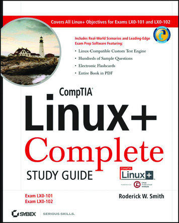
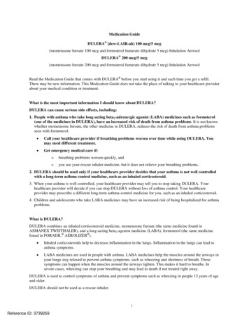
4) To view STP events as they happen, on screen: debug spanning-tree eventsc. Describe Root Bridge Election1) Switches receive BPDU (see Section d. below) msgs from each direct-connected Bridge/Switch2) When the initial BPDU msgs are sent, the Root Bridge ID & Sender’s Bridge ID are the samevalue, of the Sender’s Bridge ID (Priority MAC Address)a) Bridge ID – consists of 2byte (16bit) Priority and 6byte (48bit) MAC Addressb) Priority – consists of Priority Field & System ID Extension (the VLAN ID)i. Priority field – 4bits and always set to 1000; counting the binary values from RIGHT to left,to include 12bit Sys ID Extension, this “one” bit value 32,768 (the 15th bit of the 16bitstring of binary values)ii. System ID Extension (i.e. VLAN ID) 0000 0000 0001, for VLAN 1 (Default)iii. Default Priority value for a given Bridge ID is 32,769 (32,768 1 ; 1000 0000 0000 0001)c) MAC Address – single burned-in physical address assigned to each Switch3) A Switch receives a BPDU & compares the Sending Switch’s Bridge ID to its own Bridge ID4) The Switch will determine the lowest Bridge ID (Priority MAC) & the Switch with the lowestBridge ID will become the Root Bridge5) Subsequent BPDU msgs will be updated with the new Root Bridge ID and the Switch’s ownBridge ID6) To change the elected Root Bridge, the Priority can be modified by 2 methods:a) Go into Config Mode: conf tb) Make Priority change for the STP “instance” (VLAN ID) wanting to change Root for:spanning-tree vlan 1 priority 16384 or spanning-tree vlan 1 rootprimary , which automatically changes the priority value such that the given Switch willbecome the Root Bridge1. If current Root has higher Priority value than 24576, the local Switch configuring to bePrimary will use its Priority value as 245762. If current Root has lower Priority value than 24576, the local Switch configuring to bePrimary will use its Priority value lower than 24576 but as close to 24576 as possible3. When configuring secondary Switch, the Priority value will be 28672 on the local Switchregardless of current Root Switch Priority valuec) Verify: show spanning-tree or show per VLAN: show spanning-tree vlan 10POSSIBLE PRIORITY FIELD VALUES (Increments of 4096)
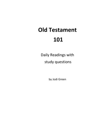
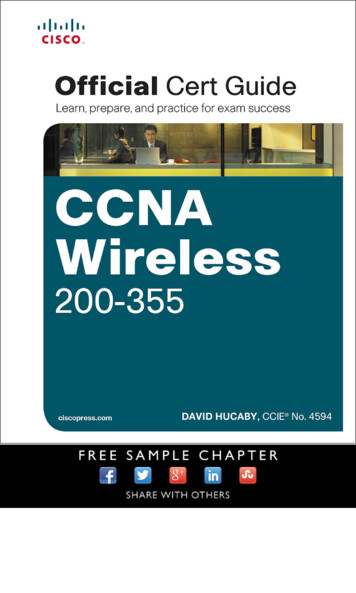
STP PORT COST VALUES BASED ON SWITCH PORT SPEEDPort SpeedPort Cost10Mbps (Ethernet)100100Mbps (Fast Ethernet)191Gbps (Gigabit Ethernet)410Gbps (10 Gigabit Ethernet) 2d. Spanning Tree Mode – Protocol created to prevent Layer 2 Loops among Bridges & Switches1) Topologya) Bridge Protocol Data Unit (BPDU) – msg initiated by the Root Switch to Nonroot Switches,sent every 2 seconds by default; BPDU contains:1. Root Bridge ID2. Sender’s Bridge ID3. Sender’s Root Port Cost – link cost value (see values above) x number of link hops to theRoot Bridge; lowest value better Cost; i.e. best link “cost” to the Root Switch4. Timer Values of Root Bridgei. Hello – default 2 secs; how often Hellos are sentii. MaxAge – default 10 x Hello Timer (i.e. 20 secs); wait time between Hellos beforeconsidered to be a downed link; NOTE: RSTP MaxAge 3x Helloiii. Forward Delay – default 15 secs; time Port stays in Listening & then Learning State(15secs ea.)b) Root Bridge – Switch with lowest Bridge ID in a Spanning Tree segment (per VLAN)c) Sender’s Bridge ID – Bridge ID of an individual Switchd) Root Port (RP) – Nonroot Switch Port with lowest cost to the Root Switch1. Determined by lowest Cost link to the Root Bridge (see Port Costs in Table above)2. If Cost among Switches is equal, then the lowest Bridge ID is used3. If still cannot be determined, the Port Priority is used4. Port ID is used as last resort5. Forwards data Frame traffic but does not send BPDUse) Designated Port (DP)1. All Root Switch ports, or 2. Determined by lowest Root Port Cost among Nonroot Switches1. If Cost is the same, then determined by lowest Bridge IDf) Non-Designated Port (Blocking Port)1. Switch Port configured by STP process to be in Blocking State to prevent L2 Loops2. Shown as “Alternate” under the Port ‘Role’ heading in the show spanning-tree cmd2) Since the Priority part of the Bridge ID is partly comprised of the VLAN ID, each SwitchVLAN/Broadcast Domain runs its own Spanning Tree instance3) Three Modes:a) PVST – Per-VLAN Spanning Tree Plus; default in Cisco IOS (no spanning-tree mode cmdneeded)b) RPVST – Rapid Per-VLAN Spanning Tree ( spanning-tree mode rapid-pvst )c) MST – Multiple Spanning Tree ( spanning-tree mode mst )4) STP Algorithm Processa) Elect Root Bridge1. Switch with lowest Bridge ID (Priority MAC)b) Determine Switch Root Ports (RP)
1. Can *only* be on Nonroot Switches, & only 1 Port on a Switch2. Determined by the Interface with the least Cost to reach the Root Switch (least Root Cost;see RP Cost defaults for Interface speed types in the Table above)c) Determine Designated Ports (DP)1. All Ports on a Root Switch are DP2. Determined by Interface that advertises the least Root Cost, or if Costs tie, the Switch withthe lower Bridge ID (or Switch with lower Interface STP Priority, or lowest Interface Port #)d) Place DPs in Forwarding StateSECTION II (26%) – IP Routing Technologies2.1 – Describe The Boot Process of Routersa. Router Boot Process1) POST process to discover hardware & verify components work properly2) Bootstrap is copied from ROM memory into RAM & runs3) Bootstrap decides which IOS image to load into RAM & loads ita) If no OS found, device boots into ROM Monitor Mode (ROMMON)4) After the OS is loaded, the bootstrap sends hardware control to the newly loaded OS5) Bootstrap then finds the Startup-config file in NVRAM then loads it into RAMa) If no Config file found, the Router broadcasts for a TFTP server containing a Config2.2 – Configure & Verify the Operational Status of a Serial Interfacea. Configure1) int s0/0/12) ip address #.#.#.# #.#.#.#3) encapsulation ppp (or another protocol; Cisco uses HDLC by default if no encapsulationcmd is used)4) no shutb. Verify1) show run int s0/0/02) show int brief2.3 – Manage Cisco IOS Filesa. Boot Preferences1) For Router devices only, this is determined by the Configuration Register (4-digit HEX number)a) 0x these digits mean whatever follows them are HEX (e.g. 0x2102 2102 are HEX)b) 16bit number (4 sets of 4 digits ####.####.####.####, numbered 0-15 from RIGHT to left)c) 4th (last/far right) HEX field is called the Boot Field (0x2102)1. 2 [0010] Default; boot as what is configured in the Boot System Field in the Startup-config2. 1 [0001] Boot to first Image file found in Flash3. 0 [0000] Boot to ROMMON Mode4. If 2 is config’d, the Router tries each boot system cmd in the startup-config file in order5. If nothing works from Step 4, the Router loads the first IOS file found in Flash (in order if
none found)d) Console Port Speed – bits 5, 11, 12 (###012.011###.##05#.####)1. [00 0] Default; 9600bps2. [00 1] 19,200bps3. [11 1] 115,000bpse) NVRAM Contents 6th bit in 3rd HEX quartet (####.####.#06##.####)1. 0 [0000] Default; load contents in NVRAM (i.e. the Startup-config file)2. 4 [0100] Ignore NVRAM contents (i.e. do not load Startup-config filei. 0x2142 Config Reg value is used for Password Recovery2) config.text – Switch only (i.e. startup-config)3) vlan.dat – DB file on Switches that stores VLAN IDs 1-1005; VLANs 1006-4094 in Config fileb. Cisco IOS Images1) To load a new imagea) Download an image from Ciscob) Place the image somewhere reachable to the Routerc) Copy the image into Flash: copy tftp flash1. Once the above cmd is entered the Router prompts for tftp server IP & IOS Image file name2) To verify the file was loaded to Flash: show flash3) To boot to the newly loaded image, add a cmd to the startup-config: boot systemflash:imageFilename.bin4) Save the Config: copy run start5) Reboot the Router to boot into new image: reload6) Verify image loaded (check IOS version): show versionc. Licensing1) Universal Image – IOS Image containing all Cisco feature sets (i.e. technology packages)2) Software activation – enables feature set paid for; verifies legal rights /access of the customer3) Technology package types:a) ipbasek9 – IP Base feature set; on all Routers by defaultb) datak9 – Data feature set; MPLS, ATM, Multiprotocols, etc.c) uck9 – Unified Communications feature set; VoIP, IP Telephonyd) securityk9 – Security feature set; Firewall, IPS, IPsec, VPN, etc.4) Licenses can be auto-managed by Cisco License Manager – app installed on Win or other OS:a) CLM communicates with Cisco License Registration Portal via Internetb) CLM takes input info about license feature sets purchased from any resellerc) CLM communicates with the org Routers/Switches to install license keys & enableappropriate feature sets5) Unique Device Identifier (UDI) – 2 part number that supports software licensing on Ciscodevices, made up of Product ID & device S/N (e.g. CISCO2901/K9:FTX162883H0)a) To view: show license udi6) Product Authorization Key (PAK) – “receipt” for proof of feature set license purchase7) License key retrieval/installation:a) Go to Cisco’s License Portalb) Enter UDI (# retrieved from Step 5 above)c) Enter PAK (retrieved after license purchase; fil
ICND2 -200-101 Study Guide (CCNA) SECTION I (21%) – LAN Switching Technologies 1.1 – Identify Enhanced Switching Technologies a. Rapid Spanning Tree Protocol (RSTP); IEEE 802.1w 1) This is ability to by-pass the full 50sec 4-state STP convergence process