Transcription
PRESSURE SEALS, Inc. 81 Commerce Way, South Windsor, CT 06074DESIGN ENGINEERS’ O-RING SIZE GUIDEINTRODUCTION:Substantially all O-ring manufacturers present their catalog data in therotation of “groupings” or “families” of cross-sectional thickness first, thenfollowed by dimensions of inside diameter. All sizes with 1/16” nominal wallare listed first, followed by rings with 3/32” wall, then 1/8” wall, etc. This isthe same mode of presentation found in the ARP 568 Uniform-NumberingSystem, published as the Aeronautical Recommended Practice Report of theSociety of Automotive Engineers. The same practice of detailing sizes bycross-sectional “families” is found in government specifications AN 6227, AN6230, MS 9021, MS 15993, MS 28775, MS 29513, etc.HEADACHE FOR DESIGN ENGINEERS:A frequent result of this established mode of O-ring size presentation is thelaborious task of “plowing through” several sections of specification data. Inactuality, the design engineers usually are involved first with the outside orinside diameter in a sealing application before they want to make adetermination as to what wall thickness or cross-sectional diameter of rubberseal they wish to consider in their design.RESCUE OPERATIONS:Many O-ring applications, of course, involve metal parts turned out on lathesand screw machines. Inevitably, some large production runs are foundbeyond tolerance. The established O-ring size will not perform its sealingfunction. Many dollars worth of expensive metal and material go down thedrain. However, the resourceful design engineer can rescue the situationoftentimes by the use of a special size O-ring.CIRCLE SIZE ROTATION:We acknowledge gratefully the advice given to us by many design engineersthat circle diameters are much more significant to them as their first level ofconsideration. In this GUIDE we have listed all Pressure Seals’ O-rings, forwhich high production tooling is available, in progressive order by outsidediameter first, followed next by inside diameter, and then by wall thicknessor cross-section. The first three columns are in the regular English inchsystem to the nearest thousandth of an inch. In the same order, the data isrepeated in the metric system. The final right-hand column gives the catalognumber for ordering purposes, and the catalog page on which tolerances arePhone: (877)-PSI-SEAL Toll Free, In CT: (860) 282-9100, Fax: (860) 282-9001
PRESSURE SEALS, Inc. 81 Commerce Way, South Windsor, CT 06074specified and on which, in most instances, you may find a full-size drawing toassist you in your consideration of the O-ring.DESIGN DIMENSIONS FOR O-RING INSTALLATIONO-rings are normally used as seals in several ways, and dimensions of thegroove or gland will also vary with the cross section of the ring, the type ofoperation, and the amount of pressure used in the system. These dimensionswill also be different if the O-ring is sealing a liquid which has a low volumeswell on the ring (0-15% Design Chart 1&3) or if it is sealing a liquid whichhas a high volume swell on the ring (15-25% Design Chart 2&4). It has notbeen practical to attempt to seal liquids which will swell the O-ring more than25%, in most cases, since the rings will lose most of their desirable physicalproperties with such a high swell.STATIC SEALS (Design Charts 1,2,3&4)In a static seal, where the O-ring does not move and is used simply forcontaining pressure or maintaining a vacuum, the ring may be compressedAXIALLY or parallel to a line drawn through the center or axis of the ring. Inthis case, you will use the dimensions under AXIAL opposite the cross sectionof the ring you desire.Although the depth and width of the groove will remain the same for all Axialstatic seals, the I.D. and O.D. of the groove will vary depending on whetheryou are sealing against internal pressure or external pressure (a vacuum in thevessel being sealed.).In the case of internal pressure, the O.D. of the groove should be the same asthe O.D. of the ring, plus the normal tolerance for that size ring.In the case of external pressure (i.e., a vacuum in the vessel being sealed),the I.D. of the groove should be the same as the I.D. of the ring being used,plus the normal tolerance range for that size ring.A static seal ring may also be compressed RADIALLY; that is, beingcompressed between the internal diameter (I.D.) and overall diameter (O.D.).In this case, you will use the dimensions under RADIAL opposite theappropriate cross section column for the ring you wish to use.Phone: (877)-PSI-SEAL Toll Free, In CT: (860) 282-9100, Fax: (860) 282-9001
PRESSURE SEALS, Inc. 81 Commerce Way, South Windsor, CT 06074DYNAMIC SEALS (Design Charts 1,2,3,4&5)Dynamic or moving seals basically fall into two classes; reciprocating (as in thecase of the piston and a cylinder), or rotating (as in the case of a shaft rotatingin a housing). Reciprocating design data will be found in Charts 1,2,3&4.Rotating design data will be found in Chart 5.Reciprocating seals may be designed so as to permit or prevent rolling of thering within the groove. When the ring is allowed to roll within the groove, thebreakaway force necessary to move the piston is usually lower; but somesacrifice must be made in the pressure limitations of the seal and also in thelife of the seal. This is caused by the constant flex of the O-ring with eachstroke of the piston.DIAMETRAL CLEARANCE (Design Chart 6)Under the dynamic section you will also find a section on diametralclearance. This calls out the maximum clearance between a piston andcylinder for pressure to 1500 psi, using a 70 durometer compound (low swellfluid) or a 60 durometer compound (in a high swell fluid). If higher pressuresare required, a different durometer O-ring may be used, as shown in DesignChart 6; or Teflon back-up rings, as shown in Design Chart 7. Design Chart 6gives an elaboration of the diametric clearance for various durometers andvarious pressures. Adherence to there clearances will largely prevent extrusionof the O-ring between the piston and cylinder or shaft and groove, up to 5,000psi using 90 durometer compound.ROTATING SEALS (Design Chart 5)Rotating seals should be limited to shafts having the following maximumrotational speed:Shaft Diameter .125 - .280 – 350 ft./minShaft Diameter .281 - .625 – 400 ft./minShaft diameter .626 - .687 – 450 ft./minShaft Diameter .688 – 1.250 – 600 ft./minIn rotating shaft seals, a higher durometer (80-90) compound is usually used.Preferably, it should have excellent abrasion resistance and quite often isinternally lubricated with graphite or molybdenum disulfide to give maximumprotection if run dry.Phone: (877)-PSI-SEAL Toll Free, In CT: (860) 282-9100, Fax: (860) 282-9001
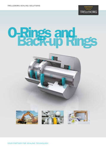
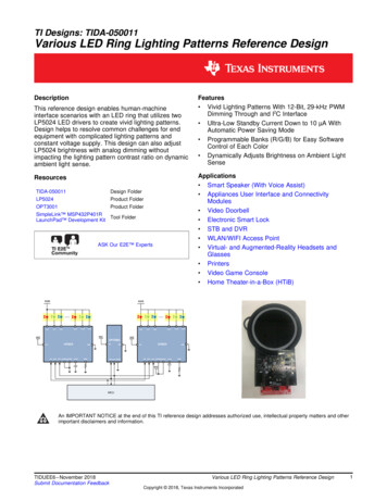
PRESSURE SEALS, Inc. 81 Commerce Way, South Windsor, CT 06074To find the groove dimensions on a rotating seal, use Design Chart 5. Find theshaft size in the second column. The groove root diameter and width will befound under their respective columns. The Pressure Seals O-ring size will befound in the first column next to the shaft diameter.BACK-UP RINGS (Design Chart 7)When you have a tendency for O-rings to extrude between the sealing areasunder pressure, there are three choices available to minimize this:1. A harder O-ring material may be used.2. Clearances may be reduced to a minimum.3. Back-up rings may be used.Design Chart 7 shows the groove width necessary to accommodate thethickness of the back-up rings. Teflon back-up rings are usually furnished insingle or dual turn rings. Single turn rings conform to MS 28774 and match thestandard P.A.I. O-ring sire. Dual turn rings conform to MS 28782 and matchthe dash numbers of an AN 6227 series of O-rings. MS 28783 back-up ringsmatch the dash numbers an AN 6230 O-rings.Good practice is to use a back-up ring on either side of the O-ring, eventhough the pressure on the ring may be from one side only. The only time youwill design for a back-up ring on one side is when there is not enough spacefor two rings. This is not recommended, however, unless absolutely necessary.STATIC SEAL: EXAMPLE RADIAL SEALIt is desired to seal a pressure vessel filled with air at 200 psi. The I.D. of thevessel at the sealing lip is 3.000” and the thickness of the cover at the groovepoint is .250”.Phone: (877)-PSI-SEAL Toll Free, In CT: (860) 282-9100, Fax: (860) 282-9001
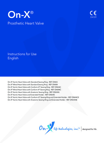
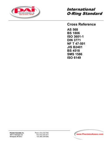
PRESSURE SEALS, Inc. 81 Commerce Way, South Windsor, CT 06074First: Pick a ring series that has a cross section which can be cut into the coverwithout weakening the cover at this point. (100 series)Second: Find an O-ring in this series which has an O.D. closest to 3.000” (1149-O.D. 3.006).Third: Check the swell characteristics of air, with possible oil traces in it. (Lowswell – 0-15%)Fourth: In the normal swell Design Chart 1, find the cross section column forthe 100 series rings (.103 .003).Fifth: In this column, opposite the RADIAL section, find the groove depth(.083-.003) and the groove width (.125 .005).STATIC SEAL – EXAMPLE: AXIAL SEALIt is desired to seal a pressure vessel filled with hydraulic oil at 1200 psi. TheI.D. of the vessel is 4 inches, and the flange is 1 inch wider and 3/8” thick (seedrawing).First: Find the O-ring sizes that will fit within the sealing area. (I-244, I-156)Second: Pick the series O-ring desired, based on the thickness of the flangeavailable to cut the groove depth desired. (I-244)Third: Check the swell characteristics of the fluid on the rubber to determinewhether the normal or high swell chart will be used for dimensions of the Oring groove. (In this case 0-15% or normal swell Chart I)Phone: (877)-PSI-SEAL Toll Free, In CT: (860) 282-9100, Fax: (860) 282-9001
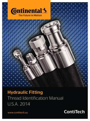
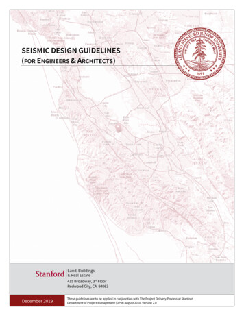
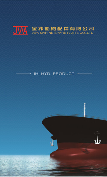
PRESSURE SEALS, Inc. 81 Commerce Way, South Windsor, CT 06074Fourth: Since this is an internal pressure application, the O.D. of the grooveshould be the O.D. of the ring (4.512) plus the tolerance (.015) or 4.527inches.Fifth: Since this is an axial squeeze, look in the AXIAL section, Design Chart 1,under the cross section of the ring (.139). The groove depth will be .110”.008” and the width will be .185 .005.DYNAMIC SEAL: RECIPROCATING, Low PressureA piston moves back and forth in a 1.000” cylinder to pump acetone at apressure of 200 psi, maximum. An O-ring seal is required for this piston.First: Find ring sizes whose O.D. is close to 1.000” (I-117, I-210)Second: Check the swell characteristics of the liquid being pumped. (Acetoneswells most rubbers but does not attack EPDM rubber, so an EPDM ring couldbe used with normal swell – table I)Third: Opposite the dynamic section under the cross section of the 100 series(.103 .003), find the depth of the groove (.090-.003) and the width of thegroove (.120 .005). If it were desired that the ring roll in the groove, thewidth would be .145 .005.DYNAMIC SEAL: RECIPROCATING, High PressureA piston seal is desired for a high pressure piston at 3,000 psi using hydraulicoil. Piston diameter is .875”.Phone: (877)-PSI-SEAL Toll Free, In CT: (860) 282-9100, Fax: (860) 282-9001
PRESSURE SEALS, Inc. 81 Commerce Way, South Windsor, CT 06074minute. The shaft diameter is 1.000 inches. The material being mixed is ablend of oil and detergents.First: In Design Chart 5, find in the second column the shaft size (1 inch)Second: Under the groove root diameter, find the root diameter (1.265).Third: Under the groove width column, find the groove width (.157).Fourth: Under the radial clearance column, find the clearance of the shaft inthe housing (.0015-.002).Fifth: Under the bearing I.D. tolerance, find the clearance of the shaft in thebearing (-.0000 .0012).Sixth: On the extreme left column, find the P.A.I. O-ring size (I-215).DESIGN CHART #1 INDUSTRIAL O-RINGS – NORMAL SWELL (0-15%)O-RINGCROSS SECTIONPSISIZE NUMBERRANGEO-RING IDSIZE RANGEAXIALSQUEEZE (min.).040 39GLANDDEPTH (max.)GROOVEWIDTH (min.)(Wall to Wall)RADIALSQUEEZE (min.)GLANDDEPTH (max.).027-.002.063 .002.035-.002.073 .003.043-.002.084 .003.051- .004.095 .003.050- .004.095 .003.080-.006.145 .005.110-.008.185 .005.175-.010.285 .005.230-.010.375 .005.007.030-.001.010.037-.001.012.045 .001.014.053-.001.015.052-.002.017.083 .003.020.115 .004.025.180 .005.035.234 .006GROOVEWIDTH (min.)(Wall to Wall)DYNAMICSQUEEZE (min.).056 .002.064 .003.075 .003.090 .003.090 .003.125 .005.170 .005.240 .005.315 .005.005.006.008.009.010.010.012.017.029GLANDDEPTH 2.090-.003.123-.004.188-.005.240-.0061/321/16.050 .003.060 .003.070 .003.070 .003.103 .003.139 .004.210 .005.275 4041-4761-7/827Phone: (877)-PSI-SEAL Toll Free, In CT: (860) 282-9100, Fax: (860) 282-9001
PRESSURE SEALS, Inc. 81 Commerce Way, South Windsor, CT 06074GROOVE WIDTHWith Roll.063.073.084.095.095.145.185.285.375No Roll(Tolerance forboth)DIAMETRALCLEARANCE (max.)*.056 .003.064 .003.075 .003.090 .003.090 .003.120 .005.160 .005.235 .005.310 .005500 psi1500 psiR RADIUS .004.016.008.060.005* These maximum diametrical clearances based on 70 Durometercompound. If harder compound is used, see Chart 6 for propermaximum clearance.DESIGN CHART #2 INDUSTRIAL O-RINGS -HIGH SWELL (15-25%)O-RINGCROSS SECTIONPSISIZE NUMBER RANGE.040 .0031-0019021/21/321/16.050 .003.060 .003.070 .003.103 .003.139 .004.210 .005.275 2-.002.040-.002.047- .317.418.008.010.012.014.017.020.025.035GLANDDEPTH 2.115-.003.180-.003.234-.004GROOVEWIDTH (min.).065.076.088.103.154.204.305.405O-RING IDSIZE RANGEAXIALSQUEEZE (min.)GLANDDEPTH (max.)GROOVEWIDTH (min.)(Wall to Wall)RADIALSQUEEZE (min.)GLANDDEPTH (max.)GROOVEWIDTH (min.)(Wall to Wall)DYNAMICSQUEEZE (min.)Phone: (877)-PSI-SEAL Toll Free, In CT: (860) 282-9100, Fax: (860) 282-9001
PRESSURE SEALS, Inc. 81 Commerce Way, South Windsor, CT 06074(Wall to Wall)DIAMETRALCLEARANCE (max.)*250 psi1000 psiRADIUS 006*These maximum diametral clearances based on 60 Durometercompound. If harder compound is used, see Chart 6 for propermaximum clearance.DESIGN CHART #3 900 SERIES O-RINGS – NORMAL SWELL (0-15%)O-RINGCROSS SECTIONPSISIZE NUMBERRANGEO-RING IDSIZE RANGEAXIALSQUEEZE (min.).056 .0031-901.185.064 .0031-9021-903.072 .0031-9041-905.239.301.351.415.078 .003.082 .003.087 .0031-9061-9071-908.468.530.644.097 .0041-9091-910.116 .0051-9111-916.118 014.016.017.020.025.030.039GLANDDEPTH (max.)GROOVEWIDTH (min.)(Wall to Wall)RADIALSQUEEZE (min.)GLANDDEPTH (max.).040-.002.079 .002.046-.002.088 .003.051-.002.095 .003.058- .004.107 .003.065- .005.120 .003.072-.005.130 .004.080-.006.145 .005.090-.006.158 .005.090-.006.158 094-.003.018.094-.003GROOVEWIDTH (min.)(Wall to Wall)DYNAMICSQUEEZE (min.).070 .003.052 .003.090 .003.098 .003.107 .004.183 .004.125 .005.140 .005.142 .005.007.008.009.009.009.010.010.011.011GLANDDEPTH 1.072-.002.084-.003.101-.003.103-.006GROOVE WIDTHWith Roll.079.088.095.105.111.117.145.158.160.068 .003.078 .003.090 .003.098 .003.139 .004.109 .004.120 .005.145 .005.146 .005No Roll(Tolerance forboth)Phone: (877)-PSI-SEAL Toll Free, In CT: (860) 282-9100, Fax: (860) 282-9001
PRESSURE SEALS, Inc. 81 Commerce Way, South Windsor, CT 06074DIAMETRALCLEARANCE (max.)*500 psi1500 psiR RADIUS 02.011.006.022.002* These maximum diametrical clearances based on 70 Durometercompound. If harder compound is used, see Chart 6 for relativemaximum clearance.DESIGN CHART #4 900 SERIES O-RINGS – HIGH SWELL (15-25%)O-RINGCROSS SECTIONPSISIZE NUMBERRANGEO-RING IDSIZE RANGEAXIALSQUEEZE (min.)GLANDDEPTH (max.)GROOVEWIDTH (min.)(Wall to Wall)RADIALSQUEEZE (min.)GLANDDEPTH (max.)GROOVEWIDTH (min.)(Wall to Wall)DYNAMICSQUEEZE (min.)GLANDDEPTH (max.)GROOVEWIDTH (min.)(Wall to Wall)DIAMETRALCLEARANCE (max.)*250 psi1000 psiR RADIUS (max.)ECCENTRICITY(max.).056 .003.064 .003.072 .003.078 .003.082 .003.087 .003.097 .003.116 .004.118 022.023.025.027.039-.002.042-.002.048-.002.053- .002.056- 10.005.020.002.010.005.020.003Phone: (877)-PSI-SEAL Toll Free, In CT: (860) 282-9100, Fax: (860) 282-9001
PRESSURE SEALS, Inc. 81 Commerce Way, South Windsor, CT 06074* These maximum diametrical clearances based on 60 Durometercompound. If harder compound is used, see Chart 6 for relativemaximum clearance.DESIGN CHART #5 ROTATING SHAFT onActualShaftDia.SDGrooveRootDia.RDGrooveWidthW .000-.000 .002 ce1-0071-0081-0091/85/323/16.145 .005.176 .005.208 .005.070 .003.070 .003.070 00- .0008-.0000- .0008-.0000- .00081-01070-2701-0117/321/49/32.239 .005.270 .005.301 .005.070 .003.070 .003.070 -.0000- .0008-.0000- .0008-.0000- .00081-1101-1111-1125/163/87/16.362 .005.424 .005.487 .005.103 .003.103 .003.103 15-.0000- .0010-.0000- .0010-.0000- .00101-1131-1141-1151/29/165/8.549 .005.612 .005.674 .005.103 .003.103 .003.103 000- .0010-.0000- .0010-.0000- .00101-11611/16.737 .005.103 .003.687-.002.883.1177/8.001-.00015-.0000- .00101-2111-2121-2133/413/167/8.796 .006.859 .006.921 .006.139 .004.139 .004.139 000- .0012-.0000- .0012-.0000- .00121-2141-2151-21615/1611 1/16.984 .0061.046 .0061.109 .006.139 .004.139 .004.139 .0000- .0012-.0000- .0012-.0000- .00121-2171-2181-2191 1/81 3/161 1/41.171 .0061.234 .0061.296 .006.139 .004.139 .004.139 -.0000- .0012-.0000- .0012-.0000- .0012Phone: (877)-PSI-SEAL Toll Free, In CT: (860) 282-9100, Fax: (860) 282-9001
PRESSURE SEALS, Inc. 81 Commerce Way, South Windsor, CT 06074DESIGN CHART #6DIAMETRAL CLEARANCE VS. DUROMETER HARDNESSCROSS SECTION250 psi max.500 psi max.1000 psi max.1500 psi max.CROSS SECTION500 psi max.1000 psi max.1500 psi max.2000 psi max.2500 psi max.CROSS SECTION500 psi max.1000 psi max.1500 psi max.2000 psi max.2500 psi max.3000 psi max.CROSS SECTION500 psi max.1000 psi max.1500 psi 010.008SHORE A HARDNESS - 60 3.003SHORE A HARDNESS – 70 3.003.001.001.0015.002SHORE A HARDNESS – 80 5.005.003.003.004.004.002.002.003.003SHORE A HARDNESS – 90 018.016Phone: (877)-PSI-SEAL Toll Free, In CT: (860) 282-9100, Fax: (860) 282-9001
PRESSURE SEALS, Inc. 81 Commerce Way, South Windsor, CT YPECelluloseester &castor oilSiliconeGreaseRECOMMENDEDUSEHigh vacuum to 1 x 10⁻⁷TorrSUITABLEBASEPOLYMERSSilicone, Nitrile, Neoprene,Viton , Butyl, HydrinTEMPERATURE RANGEFahrenheit(Celsius)-40 to 266(-40 to 130)Vacuum, ExtremeTemperature, Heavy DutyNitrile, Butyl, Viton, Hydrin,Neoprene-100 to 400(-73 to 204)SiliconeGreaseSame as above but lighterdutySiliconeHigh vacuum, ExtremeTemp. LubricantDC-200Silicone Oil(200,000 cps)MCS 352-40 to 400(-40 to 204)Do not use on SiliconesOr Fluoro-Silicone-65 to 400(-54 to 204)Pneumatic use for HighPressure and High SpeedHigh durometer Nitrile,Neoprene, Viton, Hydrin.Not for silicones.-65 to 440(-54 to 227)Skydrol Base GreasePhosphate Ester Brake andHydraulic SystemsButylSBREPDM-65 to 200(-54 to 93)Oxweld NO.64 AntiFrictionCompoundFluorocarbonBaseCompoundU-L ApprovedAssembly OxygenSystems to500 psiNitrileEPDMVitonButyl0 to 250(-19 to 121)PetrolatumPetroleumBase GreasePetroleum BaseHydraulic FluidsOil SystemsNitrile, Acrylic, Viton,Hydrin, tic,High Pressure &High SpeedNitrile, Butyl, EPDM, Viton,SBR, Neoprene, Hydrin,Urethane, Acrylic. Not forsilicones.-65 to 400(-73 to 204)VersilubeSiliconeGreasePneumatic, 3,000 psi. –High SpeedNitrile, Neoprene, Viton,Acrylic. Do not use onSilicones.-100 to 400(-73 to 204)-20 to 180(-29 to 82)Phone: (877)-PSI-SEAL Toll Free, In CT: (860) 282-9100, Fax: (860) 282-9001
PRESSURE SEALS, Inc. 81 Commerce Way, South Windsor, CT 06074 _ Phone: (877)-PSI-SEAL Toll Free, In CT: (860) 282-9100, Fax: (860) 282-9001 To find the groove dimensions on a rotating seal, use Design Chart 5. Find the shaft size in the second column. The groove root diamete