Transcription
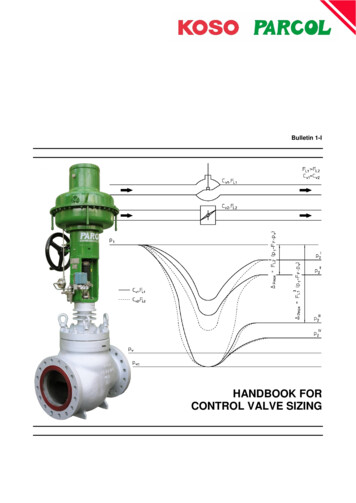
Bulletin 1-IHANDBOOK FORCONTROL VALVE SIZING
TECHNICAL BULLETIN 1-I – HANDBOOK FOR CONTROL VALVE SIZINGHANDBOOK FORCONTROL VALVE SIZINGNOMENCLATURESIZING AND SELECTION OF CONTROL VALVES0NORMATIVE REFERENCES1PROCESS DATA2VALVE SPECIFICATION3FLOW COEFFICIENT3.1 Flow coefficient KV (metric units)3.2 Flow coefficient CV (imperial units)3.3 Standard test conditions4SIZING EQUATIONS4.1 Sizing equations for incompressible fluids(turbulent flow)4.2 Sizing equations for compressible fluids(turbulent flow)4.3 Sizing equations for two-phase flows4.4 Sizing equations for non-turbulent flow5PARAMETERS OF SIZING EQUATIONS5.1 Liquid pressure recovery factor FL5.2 Coefficient of incipient cavitation xFZ andcoefficient of constant cavitation Kc5.3 Piping geometry factor FP5.4 Combined liquid pressure recovery factor andpiping geometry factor of a control valve withattached fittings FLP5.5 Liquid critical pressure ratio factor FF5.6 Expansion factor Y and specific heat ratio factorF5.7 Pressure differential ratio factor xT5.8 Pressure differential ratio factor for a valve withattached fittings xTP5.9 Reynolds number factor FR5.10 Valve style modifier Fd1
HANDBOOK FOR CONTROL VALVE SIZING – TECHNICAL BULLETIN 1-INOMENCLATURESymbolACvdDdodHFdFFFLFLPFPFRFKB1 and KB2KcKvK1 and xFZxTxTPYZ01rDescriptionflow passage area at the actual valve strokeflow coefficientnominal valve sizeinternal diameter of pipingequivalent circular flow passage diameterhydraulic diameter of a single flow passagevalve style modifierliquid critical pressure ratio factorliquid pressure recovery factor for a control valve without attached fittingscombined liquid pressure recovery factor and piping geometry factor of acontrol valve with attached fittingspiping geometry factorReynolds number factorspecific heat ratio factor / 1.4Bernoulli coefficients for inlet and outlet of a valve with attached reducerscoefficient of constant cavitationflow coefficientupstream and downstream resistance coefficientsmolecular mass of the flowing fluidabsolute thermodynamic critical pressureabsolute vapour pressure of the liquid at inlet temperaturevena contracta absolute pressureinlet absolute pressure measured at upstream pressure tapoutlet absolute pressure measured at downstream pressure tappressure differential between upstream and downstream pressuresmaximum allowable pressure differential for control valve sizing purposesfor incompressible fluidswetted perimeter of flow passagemass flow ratevolumetric flow ratemaximum mass flow rate in choked conditionmaximum volumetric flow rate in choked conditionvalve Reynolds numberinlet absolute temperatureaverage fluid velocityspecific volumeratio of pressure differential to inlet absolute pressureratio of pressure differential to inlet absolute pressure in criticalconditions ( p / p1)crcoefficient of incipient cavitationpressure differential ratio factor in choked flow condition for a valvewithout attached fittingsvalue of xT for valve / fitting assemblyexpansion factorcompressibility factor (ratio of ideal to actual inlet specific mass)specific heat ratiospecific mass of water at 15.5 C i.e. 999 kg/m³specific mass of fluid at p1 and T1ratio of specific mass of fluid in upstream condition to specific mass ofwater at 15.5 C ( 1 / 0)kinematic viscosity ( / )dynamic viscosity2Units (notes)2mmU.S. ensionlessdimensionlessdimensionless3m /hdimensionlesskg/kmolbar absolutebar absolutebar absolutebar absolutebar absolutebarbarmmkg/h3m /hkg/h3m less-6centistokes 10 m²/s-3centipoises 10 Pa s
TECHNICAL BULLETIN 1-I – HANDBOOK FOR CONTROL VALVE SIZINGSIZING AND SELECTION OF CONTROL VALVESThe correct sizing and selection of a control valve must be based on the full knowledge of the process.0. NORMATIVE REFERENCES2. VALVE SPECIFICATION- IEC 60534-2-1, Industrial process control valves –Flow capacity – Sizing under installed conditions- IEC 60534-2-3, Industrial process control valves –Flow capacity – Test procedures- IEC 60534-7, Industrial process control valves –Control valve data sheet- IEC 60534-8-2, Industrial process control valves –Noise considerations – Laboratory measurement ofnoise generated by hydrodynamic flow through controlvalvesOn the basis of the above data it is possible to finalisethe detailed specification of the valve (data sheet), i.e. toselect:- valve rating;- body and valve type;- body size, after having calculated the maximum flowcoefficient Cv with the appropriate sizing equations;- type of trim;- materials trim of different trim parts;- leakage class;- inherent flow characteristic;- packing type;- type and size of actuator;- accessories.1. PROCESS DATAThe following data should at least be known:a. Type of fluid and its chemical, physical andthermodynamic characteristics, such as:- pressure p;- temperature T;- vapour pressure pv;- thermodynamic critical pressure pc;- specific mass ;- kinematic viscosity or dynamic viscosity ;- specific heat at constant pressure Cp, specific heatat constant volume Cv or specific heat ratio ;- molecular mass M;- compressibility factor Z;- ratio of vapour to its liquid (quality);- presence of solid particles;- flammability;- toxicity;- other.b. Maximum operating range of flow rate related topressure and temperature of fluid at valve inlet andto differential pressure p across the valve.c. Operating conditions (normal, maximum, minimum,start-up, emergency, other).d. Ratio of pressure differential available across thevalve to total head loss along the process line atvarious operating conditions.e. Operational data, such as:- maximum differential pressure with closed valve;- stroking time;- plug position in case of supply failure;- maximum allowable leakage of valve in closedposition;- fire resistance;- maximum outwards leakage;- noise limitations.f. Interface information, such as:- sizing of downstream safety valves;- accessibility of the valve;- materials and type of piping connections;- overall dimensions, including the necessary spacefor disassembling and maintenance,- design pressure and temperature;- available supplies and their characteristics.3
HANDBOOK FOR CONTROL VALVE SIZING – TECHNICAL BULLETIN 1-I3. FLOW COEFFICIENT3.2 Flow coefficient Cv (imperial units)The flow coefficient is the coefficient used to calculatethe flow rate of a control valve under given conditions.The flow coefficient Cv is the standard flow rate whichflows through a valve at a given opening, referred to thefollowing conditions:- static pressure drop ( p(Cv)) across the valve of 1 psi(6 895 Pa);- flowing fluid is water at a temperature from 40 to 100 F(5 to 40 C);- the volumetric flow rate qv is expressed in gpm.The value of Cv can be determined from tests using thefollowing formula, valid at standard conditions only (referto par. 3.3):3.1 Flow coefficient Kv (metric units)The flow coefficient Kv is the standard flow rate whichflows through a valve at a given opening, referred to thefollowing conditions:- static pressure drop ( p(Kv)) across the valve of 1 bar5(10 Pa);- flowing fluid is water at a temperature from 5 to 40 C;3- the volumetric flow rate qv is expressed in m /h.The value of Kv can be determined from tests accordingto par. 3.3 using the following formula, valid at standardconditions only (refer to par. 3.3):Kvqvp( Kv )1p0Cvqvp( Cv )1p0where:- p(Cv) is the static pressure drop of 1 psi [psi];- p is the static pressure drop from upstream todownstream [psi];3- 1 is the specific mass of the flowing fluid [Ib/ft ];3- o is the specific mass of the water [Ib/ft ].where:5- p(Kv) is the static pressure drop of 10 Pa [Pa];- p is the static pressure drop from upstream todownstream [Pa];3- 1 is the specific mass of flowing fluid [kg/m ];3- o is the specific mass of water [kg/m ].3.3 Standard test conditionsThe standard conditions referred to in definitions of flowcoefficients (Kv, Cv) are the following:- flow in turbulent condition;- no cavitation and vaporisation phenomena;- valve diameter equal to pipe diameter;- static pressure drop measured between upstream anddownstream pressure taps located as in Figure 1;- straight pipe lengths upstream and downstream thevalve as per Figure 1;- Newtonian fluid.Note: Simple conversion operations among the differentunits give the following relationship: Cv 1.16 Kv.Note: Although the flow coefficients were defined asliquid (water) flow rates, nevertheless they are used forcontrol valve sizing both for incompressible andcompressible fluids. Refer to par. 5.6 and 5.9 for moreinformation.Figure 1 – Standard test set up.4
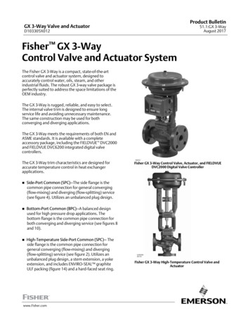
TECHNICAL BULLETIN 1-I – HANDBOOK FOR CONTROL VALVE SIZING4. SIZING EQUATIONSSizing equations allow to calculate a value of the flow coefficient starting from different operating conditions (type of fluid,pressure drop, flow rate, type of flow and installation) and making them mutually comparable as well as with the standardone.The equations outlined in this chapter are in accordance with the standards IEC 60534-2-1 and IEC 60534-2-3.4.1 Sizing equations for incompressible fluids(turbulent flow)4.2 Sizing equations(turbulent flow)In general actual flow rate qm of a incompressible fluidthrough a valve is plotted in Figure 2 versus the squarep under constantroot of the pressure differentialupstream conditions.The Figure 3 shows the flow rate diagram of acompressible fluid flowing through a valve whenchanging the downstream pressure under constantupstream conditions.The flow rate is no longer proportional to the square rootp as in the case ofof the pressure differentialincompressible fluids.This deviation from linearity is due to the variation of fluiddensity (expansion) from the valve inlet up to the venacontracta.The curve can be split into three regions:- a first normal flow region (not critical), where the flowrate is exactly proportional to p. This not critical flowcondition takes place until pvc pv.- a second semi-critical flow region, where the flow ratestill rises when the pressure drop is increased, but lessp. In this region the capabilitythan proportionally toof the valve to convert the pressure drop increase intoflow rate is reduced, due to the fluid vaporisation andthe subsequent cavitation.- In the third limit flow or saturation region the flow rateremains constant, in spite of further increments of p.forcompressiblefluidsDue to this density reduction the gas is accelerated up toa higher velocity than the one reached by an equivalentliquid mass flow. Under the same p the mass flow rateof a compressible fluid must therefore be lower than theone of an incompressible fluid.Such an effect is taken into account by means of theexpansion coefficient Y (refer to par. 5.6), whose valuecan change between 1 and 0.667.This means that the flow conditions in vena contractahave reached the maximum evaporation rate (whichdepends on the upstream flow conditions) and the meanvelocity is close to the sound velocity, as in acompressible fluid.The standard sizing equations ignore the hatched areaof the diagram shown in Figure 2, thus neglecting thesemi-critical flow region. This approximation is justifiedby simplicity purposes and by the fact that it is notpractically important to predict the exact flow rate in thehatched area; on the other hand such an area should beavoided, when possible, as it always involves vibrationsand noise problems as well as mechanical problems dueto cavitation.Refer to Figure 4 for sizing equations in normal and limitflow.Refer to Figure 4 for sizing equations in normal and limitflow.5
HANDBOOK FOR CONTROL VALVE SIZING – TECHNICAL BULLETIN 1-IFigure 2 – Flow rate diagram of an incompressible fluid flowing through a valve plotted versus downstream pressureunder constant upstream conditions.Figure 3 – Flow rate diagram of a compressible fluid flowing through a valve plotted versus differential pressure underconstant upstream conditions.6
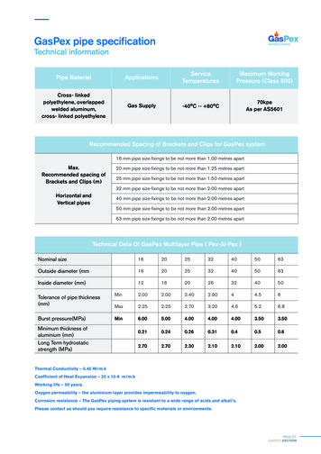
TECHNICAL BULLETIN 1-I – HANDBOOK FOR CONTROL VALVE SIZINGBasic equations (valid for standard test conditions only, par. 3.3)Kv1/qv0waterqvppSizing equations for incompressible fluids(1)FLPFppmaxxp1 FF pvp1 p2p1Turbulent flow regimeCvCvqmCvp1.16 qvFPrrCvpCvKvCvqm, qm(max)qv, qv(max)TMΔpp1 FF pv1.16 qv (max)FLPp(2) (3)FxT and/or Y230.667FxT or 2 3 Y1qm27.3 FP Yx p11M T1 ZxLimit flow (critical or chocked flow)xpmaxqm(max)865 FLP0.865qv2120 FP p1 YCvLimit flow (critical or chocked flow)pUnitsxpmax865 FPpqvNormal flow (not critical)Normal flow (not critical)pwaterCritical conditions2p1 p20Sizing equations for compressible fluidsCritical conditionsp1/qv0.865CvF18.2 FPrCvp1 FF pv3[m /h][gpm][kg/h]3[m /h] for incompressible fluids3[Nm /h] for compressible vrxT and/or YFqv (max)1414 FP p1xTP p11M T1 ZF xTP[bar a][bar a][bar a][bar a]3[kg/m ] refer to Nomenclature3[kg/m ][-][-] refer to par. 5.6Notes1) For valve without reducers: FP 1 and FLP FL2) For valve without reducers: FP 1 and xTP xT3) Formula with volumetric flow rate qv [Nm3/h] refers to normal conditions (1 013.25 mbar absolute and 273 K).For use with volumetric flow rate qv [Sm3/h] in standard conditions (1 013.25 mbar absolute and 288.6 K), replace constants2120 and 1414 with 2250 and 1501 respectively.Figure 4 – Basic and sizing equations both for incompressible and for compressible fluids for turbulent flow regime(source: IEC 60534-2-1 and IEC 60534-2-3).7
HANDBOOK FOR CONTROL VALVE SIZING – TECHNICAL BULLETIN 1-I4.3 Sizing equations for two-phase flowsNo standard formulas presently exist for the calculationof two-phase flow rates through orifices or controlvalves.The following methods are based on Parcol experienceand on the available literature; conservatively, Parcolsuggest to size the valve using both methods and toassume the higher flow coefficient resulting fromcalculations.(refer to par. 5.6), the sizing equations are:normal flowqmCv27.3 Fpqm27.3 Fpx p1veveplimit flow4.3.1 Liquid/gas mixtures at valve inletCvIn case of valve sizing with liquid/gas mixtures withoutmass and energy transfer between the phases, twophysical models can be applied.The first model is applicable for low volume fractions ofthe gas phase in vena contracta, typically lower than50% (for the evaluation of the volume fractions in venacontracta refer to paragraph 4.3.3).The method consists in the independent calculation offlow coefficients for the gaseous phase and for the liquidphase. Required flow coefficient is assumed as the sum:CvCv .gThe calculation of the flow rate of a liquid mixed with itsown vapour through a valve is very complex because ofthe mass and energy transfer between the two phases.No formulas are presently available to calculate withsufficient accuracy the flow capacity of a valve in theseconditions.On the basis of the above considerations, it is commonpractice that:- for low vapour quality at valve inlet, the most suitableequation is the one obtained from the sum of the flowcapacities of the two phases (at different flowvelocities):This model roughly considers separately the flows of thetwo phases through the valve orifice without mutualenergy exchange, assuming that the mean velocities ofthe two phases in the vena contracta are considerablydifferent.The second model overcomes the above limitationassuming that the two phases cross the vena contractaat the same velocity. It is usually applicable for highvolume fractions of the gas phase in vena contracta.According to formulas in Figure 4, the mass flow rate ofa gas is proportional to the term:xCvCv .liq Cv .vap- for high vapour quality at valve inlet, the most suitableequation is the one obtained from the hypothesis ofequal velocities of the two phases, i.e. of theequivalent specific volume ve, as shown in par. 4.3.1.14.3.3 Evaluation of volume fractions in vena contractaDefining the actual specific volume of the gas veg as:v egveF xTP p14.3.2 Liquid/vapour mixtures at valve inletCv .liqqm Yqm27.3 FpThe selection of proper sizing method between thoselisted in par. 4.3.1 depends by the ratio between thevolume fractions in vena contracta of gas and liquid,respectively qvol gas and qvol liq.The volume fractions are evaluated as follows:v g1Y2the above relation can be rewritten as:qm Yxv g1xv egIn other terms, this means to assume that the mass flowof a gas with specific volume vg1 is equivalent to themass flow of a liquid with specific volume veg under thesame operating conditions.Assuming:vefgv g1Y2qvol gasqm fg v liq1qvol liqqm fliq v liq1p1pvcThe pressure in vena contracta pvc, can be estimatedfrom the definition of the liquid pressure recovery factorFL (refer to par. 5.1).fliq v liq1where fg and fliq are respectively the gaseous and theliquid mass fraction of the mixture, and keeping in mindthat when Y reaches the value of 0.667 the flow is limit8
TECHNICAL BULLETIN 1-I – HANDBOOK FOR CONTROL VALVE SIZING4.4 Sizing equations for non-turbulent flowSizing equations of par. 4.1 and 4.2 are applicable inturbulent flow conditions, i.e. when the Reynolds numbercalculated inside the valve is higher than about 10 000(refer to par. 5.9).The well-known Reynolds number:ReDue to that above, factor FR becomes a fundamentalparameter to properly size the low flow control valves i.e.the valves having flow coefficients Cv from approximately1.0 gpm down to the micro-flows range.In such valves non-turbulent flow conditions docommonly exist with conventional fluids too (air, water,steam etc.) and standard sizing equations becomeunsuitable if proper coefficients are not used.The equations for non-turbulent flow are derived fromthose outlined in Figure 4 for non limit flow conditionsand modified with the correction factors F R and YR,respectively the Reynolds number factor and theexpansion factor in non-turbulent conditions.The sizing equations for non-turbulent flow are listed inFigure 5.u dis the dimensionless ratio between mass forces andviscous forces. When the first prevails the flow isturbulent; otherwise it is laminar.Should the fluid be very viscous or the flow rate very low,or the valve very small, or a combination of the aboveconditions, a laminar type flow (or transitional flow) takesplace in the valve and the Cv coefficient calculated inturbulent flow condition must be corrected by FRcoefficient.The choked flow condition was ignored not beingconsistent with laminar flow.Note the absence of piping factor Fp defined for turbulentflow. This because the effect of fittings attached to thevalve is probably negligible in laminar flow condition andit is actually unknown.9
HANDBOOK FOR CONTROL VALVE SIZING – TECHNICAL BULLETIN 1-ISizing equations for incompressible fluidsqmCv865 FRp1.16 qvFRCvNon-turbulent flow regime (laminar and transitional flow)Sizing equations for compressible fluidsCvqm67 FR YRCvqv1500 FR YRrrpT1p p1M T1p p1 p2Rev1000YR11000 Revx2YRRev 10009000110000x3 F xT1x21x2Reynolds number factor FRlaminar flow Rev10transitional flow 10Rev10.026FLFR0.33 FL 21nn Re vFRminmin1log40.026FL1.0010000Rev10000n Rev1.00Trim style constant nCvd20.016n467.32Cvdreduced trimCvdUnitsp2 MExpansion factor YRfull size trimNotes(1)CvqmqvTMΔp22n 1 127 Cv0.016[gpm][kg/h]3[m /h] for incompressible fluids3[Nm /h] for compressible fluids[K][kg/kmol][bar]p1p2rFRYRReVd2d32[bar a][bar a][-][-] refer to par. 5.9[-] refer to par. 5.9[-] refer to par. 5.9[mm]1) Formula with volumetric flow rate qv [Nm3/h] refers to normal conditions (1 013.25 mbar absolute and 273 K).For use with volumetric flow rate qv [Sm3/h] in standard conditions (1 013.25 mbar absolute and 288.6 K), replace constant1500 with 1590.Figure 5 – Sizing equations both for incompressible and for compressible fluids for non-turbulent flow regime (source:IEC 60534-2-1).10
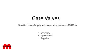
TECHNICAL BULLETIN 1-I – HANDBOOK FOR CONTROL VALVE SIZING5. PARAMETERS OF SIZING EQUATIONS5.1 Liquid pressure recovery factor FLIn addition to the flow coefficient some other parametersoccur in sizing equations with the purpose to identify thedifferent flow types (normal, semi-critical, critical, limit);such parameters only depend on the flow pattern insidethe valve body. In many cases such parameters are ofprimary importance for the selection of the right valve fora given service. It is therefore necessary to know thevalues of such parameters for the different valve types atfull opening as well as at other stroke percentages.Such parameters are:- FL liquid pressure recovery factor (for incompressiblefluids);- xFZ coefficient of incipient cavitation;- Kc coefficient of constant cavitation;- FP piping geometry factor;- FLP combined coefficient of FL with FP;- FF liquid critical pressure ratio factor;- Y expansion factor (for compressible fluids);- xT pressure differential ratio factor in choked condition;- xTP combined coefficient of FP with xT;- FR Reynolds number factor;- Fd valve style modifier.The recovery factor of a valve only depends on theshape of the body and the trim. It shows the valvecapability to transform the kinetic energy of the fluid inthe vena contracta into pressure energy. It is defined asfollows:FLp1 p2p1 pvcSince the pressure in vena contracta pvc is always lowerthan p2, it is always FL 1. Moreover it is important toremark that the lower is this coefficient the higher is thevalve capability to transform the kinetic energy intopressure energy (high recovery valve).The higher this coefficient is (close to 1) the higher is thevalve attitude to dissipate energy by friction rather thanin vortices, with consequently lower reconversion ofkinetic energy into pressure energy (low recovery valve).In practice, the sizing equations simply refer to the pressure drop (p1 – p2) between valve inlet and outlet anduntil the pressure pvc in vena contracta is higher than thesaturation pressure pv of the fluid at valve inlet, then theinfluence of the recovery factor is practically negligibleand it does not matter whether the valve dissipatespressures energy by friction rather than in whirlpools.The FL coefficient is crucial when approaching tocavitation, which can be avoided selecting a lowerrecovery valve.a. Determination of FLSince it is not easy to measure the pressure in the venacontracta with the necessary accuracy, the recoveryfactor is determined in critical conditions:FL1.16 qv (max)Cvp1 0.96 pvThe above formula is valid using water as test fluid.Critical conditions are reached with a relatively high inletpressure and reducing the outlet pres-sure p2 until theflow rate does not increase any longer and this flow rateis assumed as qv(max). FL can be determined measuringonly the pressure p1 and qv(max).b. Accuracy in determination of FLIt is relatively easier determining the critical flow rateqv(max) for high recovery valves (low FL) than for lowrecovery valves (high FL). The accuracy in thedetermination of FL for values higher than 0.9 is not soimportant for the calculation of the flow capacity as toenable to correctly predict the cavitation phenomenon forservices with high differential pressure.c. Variation of FL versus valve opening and flowdirectionThe recovery factor depends on the profile of velocitieswhich takes place inside the valve body. Since this lastchanges with the valve opening, the FL coefficientconsiderably varies along the stroke and, for the samereason, is often strongly affected by the flow direction.The Figure 6 shows the values of the recovery factorversus the plug stroke for different valve types and thetwo flow directions.Figure 6 – Typical FL values versus Cv % and flowdirection for different PARCOL valve types.11
HANDBOOK FOR CONTROL VALVE SIZING – TECHNICAL BULLETIN 1-IFigure 7 – Comparisonbetween two valves withequal flow coefficient butwith different recoveryfactor, under the same inletfluid condition.Whenvaryingthedownstream pressure, atthe same values of Cv, p1and p2, valves with higherFL can accept higher flowrates of fluid.Figure 8 – Pressure dropcomparison betweensingle stage (venturinozzle) andmultistage multipathTM(Limiphon trim)on liquid serviceusing CFD analysis.12
TECHNICAL BULLETIN 1-I – HANDBOOK FOR CONTROL VALVE SIZING5.2 Coefficient of incipient cavitation xFZ andcoefficient of constant cavitation KcIn order to detect the beginning of the constant bubbleformation, i.e. the constant cavitation, the coefficient Kcis defined as:When in the vena contracta a pressure lower than thesaturation pressure is reached then the liquidevaporates, forming vapour bubbles.If, due to pressure recovery, the downstream pressure(which only depends on the downstream piping layout) ishigher than the critical pressure in the vena contracta,then vapour bubbles totally or partially implode, instantlycollapsing.This phenomenon is called cavitation and causes wellknow damages due to high local pressures generated bythe vapour bubbly implosion. Metal surface damaged bythe cavitation show a typical pitted look with many microand macro pits. The higher is the number of implodingbubbles the higher are damaging speed and magnitude;these depend on the elasticity of the media where theimplosion takes place (i.e. on the fluid temperature) aswell ad on the hardness of the metal surface (see tablein Figure 9).Critical conditions are obviously reached gradually.Moreover the velocity profile in the vena contracta is notcompletely uniform, hence may be that a part only of theflow reaches the vaporization pressure. The F L recoveryfactor is determined in proximity of fully criticalconditions, so it is not suitable to predict an absoluteabsence of vaporization.KCppvIt identifies where the cavitation begins to appear in awater flow through the valve with such an intensity that,under constant upstream conditions, the flow ratedeviation from the linearity versus p exceeds 2%.A simple calculation rule uses the formula:KC0.80 FL2Such a simplification is however only acceptable whenthe diagram of the actual flow rate versusp , underconstant upstream conditions, shows a sharp breakpoint between the linear/proportional zone and thehorizontal one.If, on the contrary, the break point radius is larger (i.e. ifthe p at which the deviation from the linearity takesplace is different from the p at which the limit flow rateis reached), then the coefficient of proportionalitybetween Kc and FL² can come down to 0.65.Usually the beginning of cavitation is identified by thecoefficient of incipient cavitation xFZ:x FZp1Since the coefficient of constant cavitation changes withthe valve opening, it is usually referred to a 75%opening.ptrp1 pvwhere Δptr is the value of differential pressure wheretransition takes place from non cavitating to cavitatingflow.The xFZ coefficient can be determined by test usingsound level meters or accelerometers connected to thepipe and relating noise and vibration increase with thebeginning of bubble formation.Some information on this regard are given by standardIEC 60534-8-2 “Laboratory measurement of the noisegenerated by a liquid flow through a control valve”, whichthe Figure 10 was drawn from.Index of resistance to cavitationstellite gr.6chrome plating17-4 PH H900AISI 316/304monel 400gray cast ironchrome-molybdenum alloyed steels (5% chrome)carbon steels (WCB)bronze (B16)nickel platingpure gure 9 – Cavitation resistance of some metallicmaterials referred to stainless steels AISI 304/316.Values between brackets are listed for qualitativecomparison only.Figure 10 – Determination of the coefficient of incipientcavitation by means of phonometric analysis (source:IEC 60534-8-2).13
HANDBOOK FOR CONTROL VALVE SIZING – TECHNICAL BULLETIN 1-I5.3 Piping geometry factor Fp5.4 Combined liquid pressure recovery factor andpiping geometry factor of a control valve withattached fittings FLPAccording to par. 3.3, the flow coefficients of a givenvalve type are determined under standard conditions ofinstallation.The actual piping geometry will obviously differ from thestandard one.The coefficient FP takes into account the way that areducer, an expander, a Y or T branch, a bend or a shutoff valve affect the value of Cv of a control valve.A calculation can only be carried out for pressure andvelocity changes caused by reducers and expandersdirectly connected to the valve. Other effects, such asthe ones caused by a change in velocity profile at valveinlet due to reducers or other fittings like a short radiusbend close to the valve, can only be evaluated byspecific tests. Moreover such perturbations could involveundesired effects, such as plug instability due toasymmetrical and unbalancing fluid dynamic forces.When the flow coefficient must be determined within 5 % tolerance the FP coefficient must be determined bytest.When estimated values are permissible the followingequation may be used:Reducers, expanders, fittings and, generally speaking,any installation not according to the standard testmanifold not only affect the standard coefficient(changing the actual inlet and outlet pressures), but alsomodify the transition point between normal and chokedflow, so that pmax is no longer equal to FL² (p1 - FF pv),but it becomes:2pmax1K0.00214Cvd2FLPOutlet expander:In case of the sameratio d/D for reducerand expander:In case of differentratio d/D for reducerand expander:1.16 qv (max) LPCv2FLFLPK1K2K1p1 0.96 pvThe above formula is valid using water as test fluid.When FL is known, it can also be determined by thefollowing relationship:1where:- Cv is the selected flow coefficient [gpm];- d is the nominal valve size [mm];- K is defined as K K1 K 2 K B1 K B 2 , with: K1 and K2 are resistance coefficient which take intoaccount head losses due to turbulences and frictionsrespectively at valve inlet and outlet (see Figure 11); KB1 and KB2 are the so called Bernoul
5.3 Piping geometry factor F P 5.4 Combined liquid pressure recovery factor and piping geometry factor of a control valve with attached fittings F LP 5.5 Liquid critical pressure ratio factor F F 5.6 Expansion factor Y and specific heat