Transcription
CS152: Computer Systems ArchitectureRISC-V IntroductionSang-Woo JunWinter 2019Large amount of material adapted from MIT 6.004, “Computation Structures”,Morgan Kaufmann “Computer Organization and Design: The Hardware/Software Interface: RISC-V Edition”,and CS 152 Slides by Isaac Scherson
Course outline Part 1: The Hardware-Software Interfaceo What makes a ‘good’ processor?o Assembly programming and conventions Part 2: Recap of digital designo Combinational and sequential circuitso How their restrictions influence processor design Part 3: Computer Architectureo Computer Arithmetico Simple and pipelined processorso Caches and the memory hierarchy Part 4: Computer Systemso Operating systems, Virtual memory
RISC-V Introduction We use RISC-V as a learning tool A free and open ISA from Berkeleyo A clean-slate design using what was learned over decadeso Uncluttered by backwards compatibility Many, many industry backers!o Google, Qualcomm, NVIDIA, IBM, Samsung, Huawei,
RISC-V Introduction Composable, modular designo Consists of a base ISA -- RV32I (32 bit), RV64I (64 bit)o And many composable extensions. Including: We will use RV32I‘M’: Math extension. Multiply and divide‘F’, ‘D’: Floating point extensions, single and double precision‘A’: Atomic operations‘B’: Bit manipulation‘T’: Transactional memory‘P’: Packed SIMD (Single-Instruction Multiple Data)‘V’: Vector operatorsDesigner can choose to implement combinations: e.g., RV64IMFT Virtual memory (Sv32, Sv48) and privileged operations specified
Structure of the ISA Small amount of fixed-size registerso For RV32I, 32 32-bit registers (32 64-bit registers for RV64)o A question: Why isn’t this number larger? Why not 1024 registers? Three types of instructions1. Computational operation: from register file to register file xd Op(xa, xb), where Op { , -, AND, OR, , , } Op implemented in ALU2. Load/Store: between memory and register file3. Control flow: jump to different part of code
Super simplified processor operationinst mem[PC]next PC PC 4if ( inst.type STORE ) mem[rf[inst.arg1]] rf[inst.arg2]if ( inst.type LOAD ) rf[inst.arg1] mem[rf[inst.arg2]]if ( inst.type ALU ) rf[inst.arg1] alu(inst.op, rf[inst.arg2], rf[inst.arg3])if ( inst.type COND ) next PC rf[inst.arg1]PC next PCIn the four bytes of the instruction,type, arg1, arg2, arg3, opneeds to be encoded
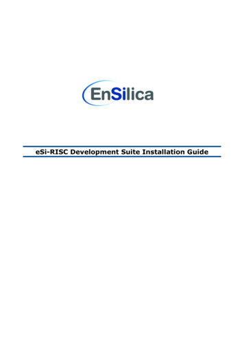
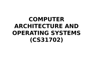
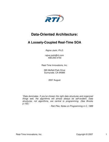
RISC-V base architecture componentsArithmetic Logic UnitRegister fileOpALUWorking data 32-bit words*ProgramBinary x0x1x2x3x4x5ProgramCounter 32 32-bit registers (64 bit words for RV64) x31 Current locationin program executionMain memory interface Input: 2 values, Op Output: 1 valueOp { , -, AND, OR, , , } Actual memoryoutside CPU chip
RISC-V assembly instructions
Three types of instructions1. Computational operation: from register file to register file2. Load/Store: between memory and register file3. Control flow: jump to different part of code
Computational operations Arithmetic, comparison, logical, shift operations Register-register instructionso 2 source operand registerso 1 destination registero Format: op dst, src1, src2ArithmeticComparisonLogicalShiftadd, subslt, sltuand, or, xorsll, srl, sraset less thanset less than unsignedSigned/unsigned?Shift left logicalShift right logicalShift right arithmeticArithmetic/logical?
Computational operations Register-immediate operationso 2 source operands One register read One immediate value encoded in the instructiono 1 destination registero Format: op dst, src, imm eg., addi x1, x2, gisteradd, subslt, sltuand, or, xorsll, srl, sraregisterimmediateaddislti, sltiuandi, ori, xorislli, srli, sraiNo “subi” instead use negative with “addi”
Aside: Signed and unsigned operations Registers store 32-bits of data, no type Some operations interpret data as signed, some as unsigned valuesoperationMeaningadd d, a, bd sx(a) sx(b)slt d, a, bd sx(a) sx(b) ? 1 : 0sltu d, a, bd ux(a) ux(b) ? 1 : 0sll d, a, bd ux(a) bsrl d, a, bd ux(a) bsra d, a, bd sx(a) bsx: interpret as signed, ux, interpret as unsignedNo sla operation. Why? Two’s complement ensures sla sll
Aside: Two’s complement encoding How should we encode negative numbers? Simplest idea: Use one bit to store the sign“0” for “ ”“1” for “-”110011 Is this a good encoding? No!o Two representations for “0” (“ 0”, “-0”)o Add and subtract require different algorithms01 “-77”
Aside: Two’s complement encoding The larger half of the numbers are simply interpreted as negative Background: Overflow on fixed-width unsigned numbers wrap aroundo Assuming 3 bits, 100 101 1001 (overflow!) stores 001o “Modular arithmetic”, equivalent to following modN to all operations Relabeling allows natural negative operations via modular arithmetico e.g., 111 010 1001 (overflow!) stores 001equivalent to -1 2 1o Subtraction uses same algorithm as adde.g., a-b a (-b)
Aside: Two’s complement encoding Some characteristics of two’s encoded numbersoooooNegative numbers have “1” at most significant bit (sign bit)Most negative number 10 000 -2N-1Most positive number 01 111 2N-1If all bits are 1 11 111 -1Negation works by flipping all bits and adding 1-A A 0Because -1 is all 1s,-A A -1 1there is no borrowing,-A (-1 - A) 1therefore subtracting A from -1 is flipping all bitse.g.,-A A 1111111-100010 011101
Return to shifting with two’s complement Right shift requires both logical and arithmetic modesoooooAssuming 4 bits(410) 1 (01002) 1 00102 210 Correct!(-410) logical1 (11002) logical1 01102 610 For signed values, Wrong!(-410) arithmetic1 (11002) arithmetic1 11102 -210 Correct!Arithmetic shift replicates sign bits at MSB Left shift is the same for logical and arithmetico Assuming 4 bitso (210) 1 (00102) 1 01002 410 Correct!o (-210) logical1 (11102) logical1 11002 -410Correct!
Three types of instructions1. Computational operation: from register file to register file2. Load/Store: between memory and register file3. Control flow: jump to different part of code
Load/Store operations Format: op dst, offset(base)o Address specified by a pair of base address, offset o e.g., lw x1, 4(x2) # Load a word (4 bytes) from x2 4 to x1o The offset is a small constant Variants for typesoooolw/sw: Word (4 bytes)lh/lhu/sh: Half (2 bytes)lb/lbu/sb: Byte (1 byte)‘u’ variant is for unsigned loads Half and Byte reads extends read data to 32 bits. Signed loads are sign-bit aware
Sign extension Representing a number using more bitso Preserve the numeric value Replicate the sign bit to the lefto c.f. unsigned values: extend with 0s Examples: 8-bit to 16-bito 2: 0000 0010 0000 0000 0000 0010o –2: 1111 1110 1111 1111 1111 1110 In RISC-V instruction seto lb: sign-extend loaded byteo lbu: zero-extend loaded byteWhy doesn’t stores need sign variants?
Three types of instructions1. Computational operation: from register file to register file2. Load/Store: between memory and register file3. Control flow: jump to different part of code
Control flow instructions - Branching Format: cond src1, src2, label If condition is met, jump to label. Otherwise, continue to nextbeqbnebltbgebltubgeu ! gcc(Assume x1 a; x2 b; x3 c;)
Control flow instructions – Jump and Link Format:o jal dst, label – Jump to ‘label’, store PC 4 in dsto jalr dst, offset(base) – Jump to rf[base] offset, store PC 4 in dst e.g., jalr x1, 4(x5) Jumps to x5 4, stores PC 4 in x1 Why do we need two variants?o jal has a limit on how far it can jump (Why? Encoding issues explained later)o jalr used to jump to locations defined at runtime Needed for many things including function calls(e.g., Many callers calling one function) jal x1, function1 function1: jalr x0, 0(x1)
Three types of instructions – Part 41.2.3.4.Computational operation: from register file to register fileLoad/Store: between memory and register fileControl flow: jump to different part of codeLoad upper immediate: Load (relatively) large immediate value
Load upper immediate instructions LUI: Load upper immediateoooolui dst, immediate dst immediate 12Can load (32-12 20) bitsUsed to load large ( 32 bits) immediate values to registerslui followed by addi (load 12 bits) to load 32 bits AUIPC: Add upper immediate to PCo auipc, dst, immediate dst PC immediate 12o Can load (32-12 20) bitso auipc followed by addi, then jalr to allow long jumps within any 32 bit addressTypically not used by human programmers!Assemblers use them to implement complex operations
What does the ISA for this look like? ADD: 0x000000001,SUB: 0x00000002,LW: 0x000000003,SW: 0x00000004, ? Haphazard encoding makes processor design complicated!o More chip resources, more power consumption, less performance
RISC-V instruction encoding Restrictionso 4 bytes per instructiono Different instructions have different parameters (registers, immediates, )o Various fields should be encoded to consistent locations Simpler decoding circuitry Answer: RISC-V uses 6 “types” of instruction encodingWe’re not going to look at everything
R-Type encoding Relatively straightforward, register-register operations encoding Remember:o if ( inst.type ALU ) rf[inst.arg1] alu(inst.op, rf[inst.arg2], rf[inst.arg3])o In 4 bytes, type, arg1, arg2, arg3, op needs to be encoded
R-Type encoding Instruction fieldsooooooopcode: operation coderd: destination register number (5 bits for 32 registers)funct3: 3-bit function code (additional opcode)rs1: the first source register number (5 bits for 32 registers)rs2: the second source register number (5 bits for 32 registers)funct7: 7-bit function code (additional opcode, func3 only support 8 functions)funct7rs2rs1funct3rdopcode7 bits5 bits5 bits3 bits5 bits7 bits
R-Type encoding Instruction fieldsooooooopcode: operation coderd: destination register number (5 bits for 32 registers)funct3: 3-bit function code (additional opcode)rs1: the first source register number (5 bits for 32 registers)rs2: the second source register number (5 bits for 32 registers)funct7: 7-bit function code (additional opcode)e.g., add x9,x20,x21funct7rs2rs1funct3rdopcode7 bits5 bits5 bits3 bits5 bits7 bits02120095100000001010110100000010010110011 0x015A04B316
I-Type encoding Register-Immediate operations encodingo One register, one immediate as input, one register as outputImmediate value limited to 12 bits signed!addi x5, x6, 2048 # Error: illegal operands addi x5,x6,2048'Operands in same location!
I-Type encoding Shift instructions need only 5 bits for immediate (32 bit words)o Top 7 bits of the immediate field used as func7o I-Type func7 same location as R-type func7 Allows efficient reuse of decode circuitry
S-Type and SB-Type encoding Store operation: two register input, no outputo e.g.,sw src, offset(base)beq r1, r2, labelS-TypeSB-TypeOperands in same location!(Bit width not to scale )
U-Type and UJ-Type encoding One destination register, one immediate operando U-Type: LUI (Load upper immediate), AUIPC (Add upper immediate to PC)Typically not used by human programmero UB-Type: JAL (Jump and link)Operands in same location!
Relative addressing Problem: jump target offset is small!o For branches: 13 bits, For JAL: 21 bitso How does it deal with larger program spaces?o Solution: PC-relative addressing (PC PC imm) Remember format: beq x5, x6, label Translation from label to offset done by assembler Works fine if branch target is nearby. If not, AUIPC and other tricks by assemblerSB-TypeU-Type
Design consideration:Consistent operand encoding location Simplifies circuits, resulting in less chip resource usage
Back to programming!
Pseudoinstructions Using raw RISC-V instructions is complicatedo e.g., How can I load a 32-bit immediate into a register? Solved by “Pseudoinstructions” that are not implemented in hardwareo Assembler expands it to one or more instructionsPseudo-InstructionDescriptionli dst, immLoad immediatela dst, labelLoad label addressbgt, ble, bgtu, bleu, Branch conditions translated to hardware-implemented onesjal labeljal x1, 0(label)retReturn from function (jalr x0, x1, 0) and more! Look at provided ISA referenceWhy x0, why x1?
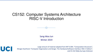
RISC-V register conventions Convention: Not enforced by hardware, but agreed by programmerso Except x0 (zero). Value of x0 is always zero regardless of what you write to it Used to discard operations results. e.g., jalr x0, x1, 0 ignores return address?Source: MIT 6.004 ISA Reference CardSymbolic names also used in assembler syntax
Calling conventions and stack Some register conventionso ra (x1): typically holding return address Saver is “caller”, meaning a function caller must save its ra somewhere before callingo sp (x2): typically used as stack pointero t0-t6: temporary registers Saver is “caller”, meaning a function caller must save its values somewhere before calling, if itsvalues are important (Callee can use it without worrying about losing value)o a0-a7: arguments to function calls and return value Saver is “caller”o s0-s11: saved register Saver is “callee”, meaning if a function wants to use one, it must first save it somewhere, andrestore it before returning“Save” where? Registers are limited
Calling conventions and stack Registers saved in off-chip memory across function calls Stack pointer x2 (sp) used to point to top of stacko sp is callee-saveo No need to save if callee won’t call another functionTypical memory mapmax Stack space is allocated by decreasing valueo Referencing done in sp-relative way Aside: Dynamic data used by heap for mallocData inprogram binaryProgram binary0
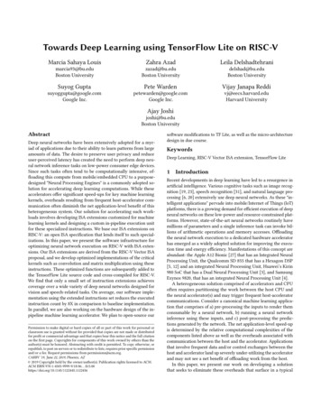
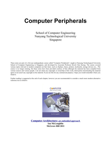
Example: Using callee-saved registers Will use s0 and s1 to implement fSource: MIT 6.004 2019 L03
Example: Using callee-saved registers(Used space)Saved s0(Used space)Saved s0Saved s1 Saved s1sp sp (Used space)Stack spStack StackBefore function callDuring function callAfter function call
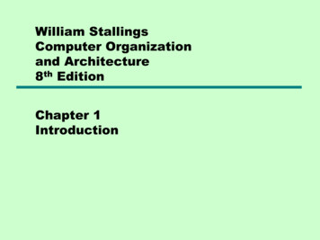
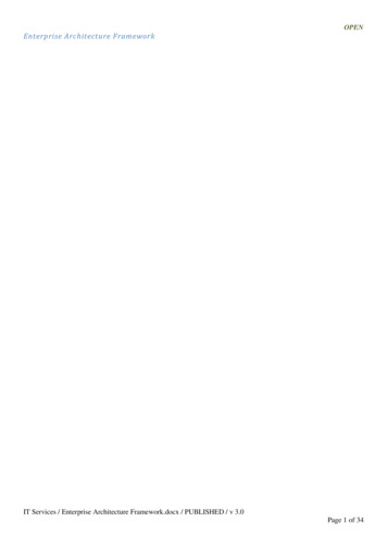
Example: Using caller-saved registersCallerCalleera is saved, meaning even if callee calls anotherfunction, caller can still retrieve its raWhy did the caller save s1?We don’t know which registers callee will useCaller must save all caller-save registers it cares aboutSource: MIT 6.004 2019 L03
Rule of thumb for register conventions Assume function “foo” calls function “bar” There are two sets of general purpose registers, t’s (t0-t6) and s’s (s0-s11)o Saved registers (s’s) are callee-save, meaning “bar” must store them somewhere ifit wants to use someo Temporary registers (t’s) are caller-save, meaning “foo” must save themsomewhere if it wants their values to be the same after returning from “bar” Argument registers (a’s) are caller-saveo If “bar” wants to call another function “bar2”, it must save the a’s it was given,before setting them to its own arguments (which is natural)
Rule of thumb for register conventions Rule of thumb for saved registerso For computation ongoing across function (“bar”) calls, use s’so Simple to just use s’s for most register usageo Each function (“bar”) stores all s’s (it plans to use) in the stack at beginning, andrestore them before returning Rule of thumb for temporary registerso Use t’s for intermediate values that are no longer important after the function call,for example calculating arguments for “bar”.o “Foo” must store t’s in stack (if it wants their values to persist) before calling “bar”,but simpler to just restrict use of t’s for values we don’t expect to persist
Rule of thumb for register conventions TL;DR: Only use callee-save registers for computation (s’s)o At beginning of function: store ra and all s’s it will useo At end of function: restore ra and all s’s from stacko Of course, a’s must be handled accordingly (caller-save) Before “foo” calls “bar”, “foo” stores all a’s in stack After “bar” returns, restores all a’s from stack (after copying return value from a0, etc)
Aside: Handling I/O How can a processor perform I/O? Special instructions? Sometimes!o RISC-V defines CSR (Control and Status Registers) instructionso Check processor capability (I/M/E/A/.?), performance counters, system calls, o “Port-mapped I/O” For efficient communication, memory-mapped I/Oo Happens outside the processoro I/O device directed to monitor CPU address bus, intercepting I/O requests Each device assigned one or more memory regions to monitorExample:In the original Nintendo GameBoy, reading from address 0xFF00returned a bit mask of currently pressed buttons
Aside: Handling I/O Even faster option: DMA (Direct Memory Access)o Off-chip DMA Controller can be directed to read/write data from memory withoutCPU interventiono Once DMA transfer is initiated, CPU can continue doing other worko Used by high-performance peripherals like PCIe-attached GPUs, NICs, and SSDs Hopefully we will have time to talk about PCIe!o Contrast: Memory-mapped I/O requires one CPU instruction for one word of I/O CPU busy, blocking I/O hurts performance for long latency I/O
Aside: Intel x86 – History Evolution with backward compatibilityo 8080 (1974): 8-bit microprocessor Accumulator, plus 3 index-register pairso 8086 (1978): 16-bit extension to 8080 Complex instruction set (CISC)o 8087 (1980): floating-point coprocessor Adds FP instructions and register stacko 80286 (1982): 24-bit addresses, MMU Segmented memory mapping and protectiono 80386 (1985): 32-bit extension (now IA-32) Additional addressing modes and operations Paged memory mapping as well as segments
Aside: Intel x86 – History Further evolution o i486 (1989): pipelined, on-chip caches and FPU Compatible competitors: AMD, Cyrix, o Pentium (1993): superscalar, 64-bit datapath Later versions added MMX (Multi-Media eXtension) instructions The infamous FDIV bugo Pentium Pro (1995), Pentium II (1997) New microarchitecture (see Colwell, The Pentium Chronicles)o Pentium III (1999) Added SSE (Streaming SIMD Extensions) and associated registerso Pentium 4 (2001) New microarchitecture Added SSE2 instructions
Aside: Intel x86 – History And further o AMD64 (2003): extended architecture to 64 bitso EM64T – Extended Memory 64 Technology (2004) AMD64 adopted by Intel (with refinements) Added SSE3 instructionso Intel Core (2006) Added SSE4 instructions, virtual machine supporto AMD64 (announced 2007): SSE5 instructions Intel declined to follow, instead o Advanced Vector Extension (announced 2008) Longer SSE registers, more instructions If Intel didn’t extend with compatibility, its competitors would!o Technical elegance market success
Aside: Intel x86 – Registers Much smaller number of registerscompared to RISC-V Four ‘general purpose’ registerso Naming has historical reasonso Originally AX DX, but ‘Extended’ to 32 bits
Aside: Intel x86 – Addressing modes Typical x86 assembly instructions have many addressing mode variantsSource/dest operandSecond source moryMemoryRegisterMemoryImmediate e.g., ‘add’ has two input operands, storing the add in the secondaddaddaddaddadd reg , mem , reg , imm , imm , reg reg mem reg mem Examplesadd 10, %eax — EAX is set to EAX 10addb 10, (%eax) — add 10 to the single byte stored at memory address stored inEAXExample source: Guide to x86 Assembly - Yale FLINT Group
Aside: Intel x86 – Encoding Many many complex instructionso Fixed-size encoding will waste too much spaceo Variable-length encoding!o 1 byte – 15 bytes encoding Complex decoding logic in hardwareo Hardware translates instructions to simplermicrooperations Simple instructions: 1–1 Complex instructions: 1–manyo Microengine similar to RISCo Market share makes this economically viableComparable performance to RISC!Compilers avoid complex instructions
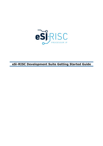
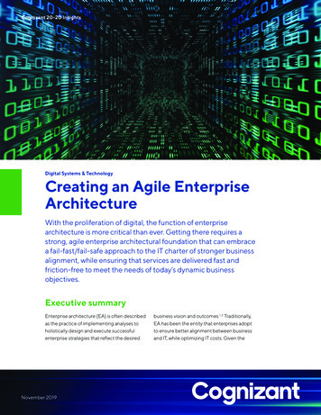
Aside: x86 – Instruction accumulation Backward compatibility instruction set doesn’t changeo But they do accrete more instructionsx86 instruction set
Wrapping up Design principles1. Simplicity favors regularity2. Smaller is faster3. Good design demands good compromises Make the common case fast Powerful instruction higher performanceo Fewer instructions required, but complex instructions are hard to implement May slow down all instructions, including simple oneso Compilers are good at making fast code from simple instructions
CS152: Computer Systems Architecture RISC-V Introduction Sang-Woo Jun Winter 2019 Large amount of material adapted from MIT 6.004, omputation Structures _, Morgan Kaufmann omputer Organization and Design: The Hardware/Software Interface: RIS -V Edition, . RIS -V Edition, and CS 152 Slides by Isaac Scherson. Course outline Part 1: The Hardware .