Transcription
To appear in the SIGGRAPH conference proceedingsComputer-Generated Pen-and-Ink Illustration of TreesOliver Deussen Thomas StrothotteFaculty of Computer Science, University of Magdeburg, GermanyAbstractWe present a method for automatically rendering pen-and-ink illustrations of trees. A given 3-d tree model is illustrated by the treeskeleton and a visual representation of the foliage using abstractdrawing primitives. Depth discontinuities are used to determinewhat parts of the primitives are to be drawn; a hybrid pixel-basedand analytical algorithm allows us to deal efficiently with the complex geometric data. Using the proposed method we are able togenerate illustrations with different drawing styles and levels of abstraction. The illustrations generated are spatial coherent, enablingus to create animations of sketched environments. Applications ofour results are found in architecture, animation and landscaping.CR Categories:I.3.3 [Picture/Image Generation]: Displayalgorithms— [I.3.7]: Three-Dimensional Graphics and Realism—AnimationIn comparison to the art-based illustration styles for trees inventedby Kowalski et al. [7], we are more interested in visually representing specific plants than to create generic representations. Our aimis to provide the user with a transition from a tree illustration with arealistic plant-specific look to an abstract representation consistingof only a few strokes. This enables the user to select a global degreeof abstraction while at the same time enabling the system to drawplants in the background with a higher abstraction level. In combination with different drawing styles, this helps to adapt the visualappearance of the plants to other objects and also, for instance, allows the user to focus the viewer’s attention on a certain part of thescene.Among the various plant types and their combinations, we focuson complex trees and bushes. Collections of these objects are mostinteresting in architecture and landscaping. Also both categoriesrequire abstract visual representations as it is impossible to drawall the geometry in detail.Keywords:Biological Systems, Frame Buffer Tricks, NonRealistic Rendering1.11Probably the first article with illustrated plants was presented byYessios [25]. In an architectural framework he used abstract plantsymbols and combined them with stones and ground materials.IntroductionDuring the last years, a variety of techniques have been proposed tosketch and non-photorealistically render objects. Research in thisarea was driven by the realization that drawings are able to conveyvisual information in a different way than photorealistic images do[21]. This is one of the reasons why a large percentage of imagesin many books are drawings (cf. [22]).While the proposed methods allow creating line drawings of manyobjects and in many different styles, the illustration of plants hasso far been neglected. This is surprising because drawings of theseobjects are needed in areas like architecture and landscaping. Inboth cases early designs are preferentially visualized as abstract linedrawings that often include many trees [18].In this paper we propose a method for automatic pen-and-ink illustration of trees. The approach allows us to create a variety ofillustration styles. The underlying models are realistic 3-d plantgeometries generated with the xfrog modeling system proposed byLintermann and Deussen [8], but any other surface-oriented plantmodel can also be used. Universitätsplatz2, D-39106 Magdeburg, Germany, odeussen@acm.orghttp://isgwww.cs.uni-magdeburg.de/ deussenRelated WorkRelated work in illustrating trees was done in the field of nonphotorealistic rendering and also in botanical plant generation.Alvy Ray Smith, one of the early authors dealing with fractals andformal plant descriptions created a “cartoon tree” with small disksrepresenting bunches of leaves [19]. A similar representation withsmaller disks was used by Reeves and Blau [14] to constitute theirstructured particle systems for rendering realistic trees. The ideaof representing numerous botanical leaves by an abstract geometricprimitive inspired us (like Kowalski et al. [7]) to work on pen-andink illustrations of trees.A line drawing is usually created by combining a number of brushor pencil strokes. Researchers in non-photorealistic rendering resemble that process by using virtual brushes. Strassmann [20] proposed the “path-and-stroke” metaphor: a path is defined and a physically simulated brush is used to generate the stroke. Hsu et al. [6]extended the metaphor by using general objects like textures, images and recursively defined fractals that are drawn along a givenpath.Salisbury et al. [16] described a method for directing the strokesin line drawings on the basis of vector fields. In their paper theyalso showed an interactively generated tree image. Winkenbach andSalesin [23, 24] presented a variety of methods for the automaticgeneration of pen-and-ink illustrations. In contrast to Strassmannand Hsu et al. they do not work with individual strokes but withartistically elaborate stroke textures.Sasada [17] presented some tree sketches in an architectural environment. He used images of synthetic tree skeletons that weremapped onto view-facing polygons. The method of Aono and Kunii [1] was used to create the skeletons, the foliage was not visualized in their computer-generated trees.Kowalski et al. [7] generated abstract sketches of trees by using geometric primitives like spheres for defining rough approximationsof a tree’s foliage. These primitives were rendered conventionally
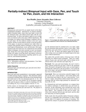
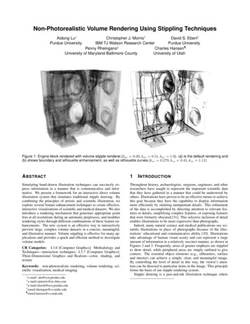
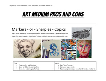
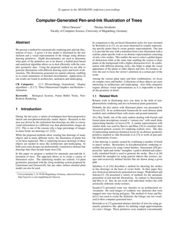
To appear in the SIGGRAPH conference proceedingsan abstract leaf representation must be found that enables the userto represent different types of leaves as well as different illustrationstyles. Third, drawing the leaves must be modulated by the threeareas: the leaves in the light must be represented solely by theoutline of the foliage, leaves in the half shadow should be drawnwith detailed outline or additional crosshatching, and regions ofdeep shadow are to be added appropriately.to achieve gray-scale images. In a second step the images wereused to place graftals – small objects representing leaves or hair –on the surfaces by applying the “difference image algorithm” proposed earlier by Salisbury et at. [16]. Doing so it is possible tocreate sketched images of generic trees, bushes, and grass.In our work we start from a different point. Our models are detailed tree models consisting of a tree skeleton and leaves. Our linedrawings are the result of visually combining many drawing primitives instead of placing graftal objects on some large geometries. Adrawback of our approach is that we potentially have to deal withmore input data. The solution to this problem is to represent a treeat several levels of detail. This makes it possible to adapt the geometric representation to what should be presented on the screen: Ifa more detailed drawing is to be created, a more detailed geometrictree description is used.The use of realistic tree models thus offers some major advantages:We can make use of existing tree libraries, our tree illustrations canbe abstract but we are also able to draw a specific plant. If the sceneis to be rendered photorealistically later, the visual representationdoes not differ much from its illustrated counterpart. Having accessto the detailed 3-d data enables us also to animate the complex linedrawings with sufficient spatial and temporal coherency. Anotheradvantage is the correct, tree-like shadow generation of our models.Tree ITree IITree IIIThe main contribution of our work is an efficient way of generating the illustration of realistic plant models using abstract drawingprimitives; furthermore, we present a “depth difference algorithm”to determine important silhouette lines, which allows us to generatedifferent levels of visual abstraction.Figure 1: Photorealistically rendered images of the synthetic sample trees: Tree I: complex tree; Tree II: young lime tree; Tree III:conifer.The remainder of this paper is organized as follows: Section 2 reviews the artistic work on illustrating trees, in Section 3 our synthetic illustration algorithm is given. Section 4 shows results, andin Section 5 we give some conclusions.32Automated Illustration of TreesThe first step to create a tree illustration is to create a tree with aconventional tree modeling program. As mentioned above, we usethe xfrog modeling system [5, 8] for that purpose. The final model– some of them are shown in Figure 1 – is preprocessed and twofiles are created.Traditional Illustration of TreesIn the first file, the geometry of the tree skeleton is stored. Likeartists we only draw the trunk and branches up to the second order in most of our illustrations with higher order branches beingremoved.Among the various styles used by artists to render trees (for a largeset of examples see [3]) one can distinguish between flat styles thatsolely represent the shape of a tree and others that also approximatenatural light interaction (cf. [9]).The tree skeleton is usually drawn up to the second branching level,primarily by silhouette lines and crosshatching on the stem surface.The shape of the foliage is either represented by an abstract outlineor by a collection of many small objects which do not necessarilyresemble natural leaves but instead represent the characteristics ofthe foliage. In addition, the outline is sometimes drawn by manysmall line segments or just a few strokes.The second file stores the leaves as particles each with a positionand a normal vector. The normal vectors are obtained by using thenormal vector of the original leaves. If too much data is generatedfor all the leaves – Tree I in Figure 1 has about 183,000 leaves –we reduce them in the modeling system by reducing the number ofleaves at each twig. If this is still too much we position the particlesat the branching positions of the highest-order twigs. In the case ofTree I we end up with 8,800 particles.The visual appearance of the foliage can be divided into three areas.The top of the tree is usually in the direct light and is thereforevisualized by only some details and its outline. In the half shadow,more details are drawn to achieve an appropriate gray level. In thisarea the outline of the leaves is often drawn in detail. The thirdarea is the shaded part. The three areas are generally not found ina single illustration, often only the half shadow and the full shadowregion is drawn. Sometimes the complete foliage is representeduniformly.The illustrations are generated as follows: The trunk and branchesare drawn by applying techniques known from non-photorealisticrendering. The foliage is rendered by representing each leaf by adrawing primitive – a disk or arbitrary polygon facing the viewer –and by applying the depth difference algorithm to determine whichpart of the primitive outlines are to be drawn. Shadows can be applied at this stage, vegetation on the ground can also be added and isprocessed the same way. The resulting drawings are then composedto constitute the final image.Artists use different methods to generate shadows on the foliage:in many styles more details are drawn and thick lines are used,sometimes with whole areas being drawn in black. Other stylesadd crosshatching to the foliage.3.1Drawing the tree skeletonThe tree skeleton is an assembly of generalized cylinders each representing a branch. The surface is more or less smooth, which allows us to apply analytical silhouette algorithms such as the oneproposed by Markosian et al. [10] or the hybrid solution of RakarA method for the synthetic illustration of trees must proposesolutions to several subproblems: First, the stem skeleton must berepresented properly by silhouette lines and crosshatching. Second,2
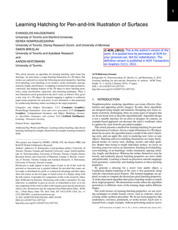
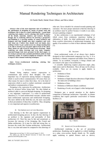
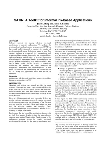
To appear in the SIGGRAPH conference proceedingsand Cohen [13] to generate the outline. The depth difference algorithm proposed below can also be applied (see Figure 2).drawn if the maximal depth difference of the surface to the neighboring surfaces is above a given threshold.In addition, the skeleton is shaded conventionally to find dark regions. These regions are then crosshatched in the drawing. The“Difference Image Algorithm” [16] that places individual strokesaccording to the local gray tone of an image is one solution to thisproblem. For our purpose a simpler method is sufficient that workswith a variant of the Floyd Steinberg method [4].Instead of computing the differences analytically - which in the caseof complex tree models is computationally expensive - we use thedepth buffer for this purpose. The primitives are drawn as solids,the depth buffer is obtained, and for each pixel the depth differenceis computed by comparing its depth value with all neighbor values.The maximal positive difference for each pixel is taken. This valueindicates how far the pixel is in front of its neighboring pixels. It isstored in a separate buffer.The algorithm places short strokes instead of pixels if the cumulatedgray scale is above a given threshold. The area of the stroke isdetermined and the corresponding error value is subtracted fromthe neighboring pixel values. The direction of the strokes is eitherat random or affected by the normal vector of the stem geometry. Asimilar technique for directing strokes was already used in [10].For interactive applications those pixels with a depth differenceexeeding a given depth difference threshold are directly used to create a bitmap of the outlines. For printing purposes a vectorizationis performed to obtain stroke pathes (see Section 3.4).It is well known that the values in the depth buffer have a non-linearcharacteristic. The depth z in the camera coordinate system or eyecoordinates rsp. is determined from a depth value d (d [0.1]) byz d z1 z0 (d1 d0 )z1 z0(z1 z0 )(d1 d0 )0) (d1 d2(z1 z0 )2(1)where d0 and d1 are minimal and maximal values represented inthe depth buffer, and z0 and z1 the corresponding depth values ofthe near and far clipping plane in the camera projection (cf. [11]).The depth differences can be computed for the depth values in eyecoordinates to achieve linear differences or directly for the depthbuffer values. In the second case depth differences for remote objects correspond to much larger differences in eye coordinates. Inconsequence the objects are represented by fewer lines.Figure 2: The trunk and main branches of Tree I are extracted andrendered by silhouette lines and cross hatching.3.2To determine a depth difference threshold sufficient for the eyecoordinates we compute the depth range of the tree and choosea percentage of this range, for example 10 percent. Analogouslythis is done with depth buffer values. The examples in this paper were rendered using depth buffer values directly by settingd0 0, d1 65535, z0 1, and z1 11. The depth difference in eye coordinates (z1 z0 ) is approximately the one of realtrees.Drawing the foliageThe foliage of a tree differs by its very nature from all smooth surfaces and therefore must be handled separately. Several thousandindividual surfaces must be combined visually into a shape or aset of strokes. In our first experiments, we placed special textureson the leaves of our realistic tree models that looked like strokes.This is a fast and simple method, but the generated images neverappeared like drawings.The observation that artists do not draw leaves correctly buttry to represent their visual appearance led us to use abstractdrawing primitives. Each leaf is represented by the outline ofsuch a primitive, whereas its position is determined by the 3-dleaf position and the size is controlled by the user. A very simpledrawing primitive is a view-facing disk. While other abstractdrawing primitives are given below, we first describe the secondingredient of our approach, the depth difference algorithm, byusing this primitive.(a)(b)Figure 3: Tree I rendered with varying disk size and depth difference threshold: a) size 0.15, threshold 1000; b) size 0.7, threshold 2000.Depth differencesDepth differences are used to determine what part of each drawingprimitive is to be drawn to constitute the foliage. Saito and Takahashi [15], two of the early authors in non-photorealistic rendering, used the depth-buffer to determine the outline of objects whichwere used to enhance photorealistic images. First and second orderderivatives in the depth-buffer were additionally computed to findimportant lines on the surface of the objects.Figure 3 shows two sketches of Tree I. In Figure 3(a) small disksare used and the threshold is low. This results in high detail and agood approximation of the real model. A more abstract renderingis achieved if disk size and threshold are enlarged (Figure 3(b)).The threshold can be constant over the whole image or can bemodulated by other buffers. In Figure 4(c) a shadow buffer wasused to reduce the threshold in the shadow. The resulting imageshows more detail in this area.While first and second order depth derivatives are helpful to findimportant lines on smooth surfaces, zero order derivatives are helpful for determing important lines in collections of isolated surfaceslike assemblies of drawing primitives: The outline of a primitive is3
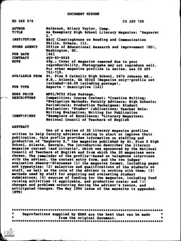
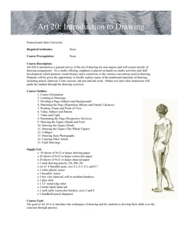
To appear in the SIGGRAPH conference proceedingsAbstract drawing primitives3.4Software FrameworkApart from disks, a number of drawing primitives can be used torepresent the leaves. In Figure 4(a) a set of nine polygons was generated to represent leaves from different views. The normals of thegiven particles were used to interpolate the individual shapes of theleaves from the polygons. Using this interpolation scheme, a 3-dshape can be denoted without strictly adhering to perspective transformations.The proposed method was designed to work in two environments.First, a fast method for interactive systems was needed. Second,high quality images should be produced for printouts, animationsand architectural sketches. As a consequence the software works instages that are partly omitted for the interactive process.In the first step, depth differences have to be determined. In theinteractive environment stem and foliage are rendered together, thedepth buffer is obtained and all pixels above the given depth difference threshold are drawn in black. The resulting bitmap is directlyused and blended with other geometries of the scene to constitutethe final image.If appropriate polygons are used, a representation similar to thegraftals in [7] can be generated, but our interpolation method offersmore freedom, allowing nearly all forms of leaves to be used.The user is also able to decide to what extent the 3-d impressionis generated: the leaves in Figure 4(b) are not drawn from the fullrange of views, instead a subset is used to generate a style betweenuniform shapes and the full 3-d impression. In Figure 4(c) the shapeof the leaves is drawn only in the shadow region, additionally thelinewidth is increased.For drawing purposes - and also for animations with high temporalcoherency - the stem and the foliage are rendered separately, theimages are combined by their depth buffer values to handle occlusion. For each image a separate depth difference threshold is usedlater.For many styles shadows have to be introduced. We have to usea software implementation of shadows because volume shadowsbased on stencil buffering (cf. [11]) do not work for the huge number of isolated surfaces in the foliage. The result is stored in a separate shadow buffer. In the interactive case, shadows are omitted.Now the threshold is applied and the pixels above the threshold aremarked. As mentioned above, the threshold can be modulated by ashadow buffer, other G-buffers (cf. [15]) or by an arbitrary spatialfunction.(a)(b)For generating high quality images, the bitmaps of the stem andthe foliage are vectorized. We implemented two methods: The firstalgorithm determines vectors globally for the bitmaps by applyingleast square fitting [12]. The second algorithm adds an index buffer,a bitmap that stores at each pixel position the primitive identification as a color value.(c)Figure 4: Two sketches of Tree II. a) The leaves are rendered usinginterpolated polygons from the nine given samples; b) Shadow isdrawn in black, threshold 100. c) Threshold is set to 6,000, shadowis represented by detail.3.3For each depth value above the threshold, it is now possible to obtain the primitive number, therefore vectorization can be performedfor each primitive separately. This results in a higher image quality,for instance closed primitive outlines can now easily be determinedand represented by closed polygons. As a drawback, the methodwhich is slow already needs even more time since the index bufferhas to be rendered and processed additionally.Level-of-AbstractionAs mentioned above, the differences in the depth buffer have anon-linear characteristic. If they are used directly instead of reprojecting them into eye coordinates, the same tree that is drawn inthe front with high detail will be sketched automatically by a fewstrokes if it is at the back.In both cases the polygons are drawn by spline interpolation, andline styles may be applied. As an example, line styles are responsible for the shading effect on the tree in Figure 3(b). Among varyingthe line width, which was done here, the styles may also affect thedirection of the line or alter the endpoints.The effect can be modulated by changing the z1 to z0 ratio of theperspective projection which is the basis for Equation (1). A smallratio causes a small non-linearity, a large ratio above 100:1 resultsin less depth resolution in the background and therefore in a smallnumber of strokes.This visual level-of-abstraction can be supported by scaling theprimitive size for trees in the background. In [7] a formula for ascale factor r for the object size of graftals is suggested which usesa weighted average between a scaling d/s (d desired screen space,s current screen space of the object) that generates primitives ofvisual constant size and primitives that have a constant object sizer w(d/s) (1 w)w [0.1].(a)In our case, we additionally allow w to be above one and in this caseomit the second term. Now, the abstract drawing primitives appearlarger in the background, which helps to achieve clear object shapeshere.(b)Figure 5: Tree I rendered for three different distances. a) Primitivesizes and threshold are constant for all distances. Visual abstractionis achieved automatically. b) Primitive sizes are enlarged up to thefactor of two for the tree in the back.In Figure 5 the process is shown. In the tree sequence of Figure5(a) level-of-abstraction was done on the basis of depth differencesonly, in Figure 5(b) the size of the drawing primitives is doubled forthe tree at the back.4
To appear in the SIGGRAPH conference proceedings4ReferencesResultsIn Figure 6(a) and (b), Tree III is drawn using view-facing ellipticprimitives of random orientation. After determining which part ofeach primitve has to be drawn, a small deformation was applied toeach outline. This helps to achieve a more sketched drawing style.[1] M. Aono and T. L. Kunii. Botanical tree image generation. IEEE ComputerGraphics and Applications, 4(5):10–34, May 1984.[2] O. Deussen, J. Hamel, A. Raab, S. Schlechtweg, and T. Strothotte. An illustration technique using hardware-based intersections and skeletons. In Proceedingsof Graphics Interface 99, pages 175–182. Canadian Human-Computer Communications Society, 1999.In Figure 6(b) all visible outlines are drawn, and a threshold of400 is used. The drawing of Figure 6(a) was created using a slightmodification of the algorithm: Only the lower part of each ellipse isdrawn when visible, the threshold having a value of 100. Renderingis performed in 10 seconds on our SGI Octane (Maximum Impact),the conifer consists of 13,200 particles.[3] L. Evans. The New Complete Illustration Guide: The Ultimate Trace File forArchitects, Designers, Artists, and Students. Van Nostrand Reinhold Company,1996.[4] R. W. Floyd and L. Steinberg. An adaptive algorithm for spatial grey scale. Proc.Soc. Inf. Display, 17:75–77, 1976.The maple tree of Figure 6(c) consists of 16,200 particles which isfar below the original model with 200,000 leaves. The parametrization of Figure 6(a) was used, threshold was set to 1,000.[5] Greenworks GbR. Home page of the xfrog modelling software. http://www.greenworks.de.[6] S. Hsu and I. Lee. Drawing and animation using skeletal strokes. In SIGGRAPH’94 Conference Proceedings, pages 109–118. ACM SIGGRAPH, July 1994.Figure 6(d) was created similar to Figure 6(a). Only 2,300 particlesare used, this causes nearly each ellipse to be visible, as a result alot of semicircles appear. Figure 6(e) used drawing primitives in theform of real leaves, a very small threshold of 10 causes all visibleoutlines to be drawn.[7] M. Kowalski, L. Markosian, J. D. Northrup, L. Burdev, R. Barzel, L. Holden,and J. F. Hughes. Art-based rendering of fur, grass, and trees. In SIGGRAPH ’99Conference Proceedings. ACM SIGGRAPH, August 1999.[8] B. Lintermann and O. Deussen. Interactive modeling of plants. IEEE ComputerGraphics and Applications, 19(1):56–65, January/February 1999.The tree in Figure 6(f) consists of 90,000 particles, very small ellipses were used, shadow is added as black regions. The groundis represented by 23,000 elliptic primitives of larger size. Only theshadow is drawn, no primitive outlines are used. In this case rendering is performed in about one minute.[9] F. Lohan. The drawing handbook. Contemporary Books, Chicago, 1993.[10] L. Markosian, M. A. Kowalski, S. J. Trychin, L. D. Bourdev, D. Goldstein, andJ. F. Hughes. Real-time nonphotorealistic rendering. In T. Whitted, editor, SIGGRAPH ’97 Conference Proceedings, pages 415–420. ACM SIGGRAPH, 1997.In the interactive version of the proposed algorithm it is possible torender three trees consisting of 20,000 primitives each and 25,000ground particles with three frames per second on our SGI Onyx 2at lower image quality. We hope to improve this in the future.5[11] T. McReynolds and D. Blyth. Advanced graphics programming techniques usingOpenGL. SIGGRAPH ’98 Course Notes, ACM SIGGRAPH, 1998.[12] J. R. Parker. Extracting vectors from raster images. Computers & Graphics,12(1):75–79, 1988.[13] R. Raskar and M. Cohen. Image precision silhouette edges. In 1999 ACM Symposium on Interactive 3D Graphics, pages 135–140. ACM SIGGRAPH, April1999.Conclusion and Future Work[14] W. T. Reeves and R. Blau. Approximate and probabilistic algorithms for shadingand rendering structured particle systems. In Computer Graphics (SIGGRAPH’85 Proceedings), volume 19, pages 313–322, July 1985.We have presented a framework for rendering trees in pen-and-ink.The tree skeleton and the foliage are processed separately. Thetrunk and branches are represented by silhouette lines augmentedby crosshatching in dark areas. The foliage is drawn by using abstract drawing primitives that represent leaves. Such primitives canbe circles, ellipses or other polygons. An interpolation scheme allows us to adapt the form of the primitives to the normal vector ofthe particles that are used as input. Depth differences are used todetermine what part of the primitives are drawn.[15] T. Saito and T. Takahashi. Comprehensive rendering of 3-d shapes. In Computer Graphics (Proc. SIGGRAPH 90), volume 24(4), pages 197–206. ACMSIGGRAPH, 1990.[16] M. Salisbury, M. Wong, J. F. Hughes, and D. Salesin. Orientable textures forimage-based pen-and-ink illustration. In SIGGRAPH ’97 Conference Proceedings. ACM SIGGRAPH, 1997.[17] T. T. Sasada. Drawing natural scenery by computer graphics. Computer AidedDesign, 19(4):212–218, 1987.Our experiments reveal that it is possible to create various illustration styles with our approach, and they have opened several areasof future research:[18] J. Schumann, T. Strothotte, A. Raab, and S. Laser. Assessing the effect of nonphotorealistic images in computer-aided design. In ACM Human Factors in Computing Systems, SIGCHI ’96, pages 35–41, April 13-15 1996. So far, shadows were introduced into the images by shadowbuffers or by raising detail in shadow regions. As mentionedin Section 2 artists sometimes use crosshatching on the leavesto represent shadow. The hatching lines in this case must interact with the leaves. An intersection method as proposedin [2] can be applied here.[19] A. R. Smith. Plants, fractals and formal languages. Computer Graphics (SIGGRAPH ’84 Proceedings), 18(3):1–10, July 1984.[20] S. Strassmann. Hairy brushes. Computer Graphics (SIGGRAPH ’86 Proceedings), 20(3):225–232, 1986.[21] C. Strothotte and T. Strothotte. Seeing Between the Pixels: Pictures in InteractiveSystems. Springer-Verlag, Berlin-Heidelberg-New York, 1997. To reduce the amount of geometric data, level-of-detail has tobe applied to the tree models. Currently we work with somediscrete representations that sometimes cause visual artifactsif representations are changed. A continuous level-of-detailalgorithm for trees will improve performance while maintaining the visual quality.[22] T. Strothotte, B. Preim, A. Raab, J. Schumann, and D. R. Forsey. How to renderframes and influence people. Computer Graphics Forum, 13(3):455–466, 1994.[23] G. Winkenbach and D. Salesin. Computer-generated pen-and-ink illustration.In SIGGRAPH ’94 Conference Proceedings, pages 91–100. ACM SIGGRAPH,1994.[24] G. Winkenbach and D. Salesin. Rendering parametric surfaces in pen and ink.In SIGGRAPH ’96 Conference Proceedings, pages 469–476. ACM SIGGRAPH,1996. The primary goal of our paper was to provide pen-and-inkillustrations for architecture and landscaping. Another important application are cartoons. New styles and colored versionsof our images need to be developed for that purpose.[25] C. I. Yessios. Computer drafting of stones, wood, plant and ground materials.Computer Graphics (Proceedings of SIGGR
We present a method for automatically rendering pen-and-ink illus-trations of trees. A given 3-d tree model is illustrated by the tree skeleton and a visual representation of the foliage using abstract drawing primitives. Depth discontinuities are used to determine what part