Transcription
Introduction to Hydraulics andPneumatics
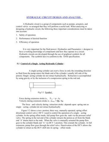
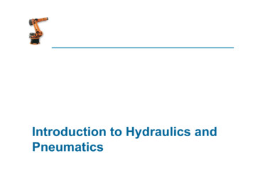
Principles of Hydraulics§ The word “hydraulics” generally refers to power producedby moving liquids. Modern hydraulics is defined as the useof confined liquid to transmit power, multiply force, orproduce motion.§ Pascal: “Pressure applied ona confined fluid is transmitted inall directions with equal forceon equal areas”.
Multiplication of Force§ heinputpiston
Components of Hydraulic/PneumaticSystems
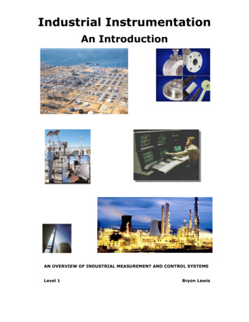
Components of Hydraulic/PneumaticSystems1. Fluid: oil for hydraulic systems, air for pneumatics.2. Reservoir: storage tank.3. Hydraulic pump (compressor in pneumatics): converts themechanical energy into hydraulic energy by forcing fluidfrom the reservoir into the system.4. Fluid lines: transport the fluid to and from the pumpthrough the hydraulic system.5. Valves: control pressure, direction and flow rate of thehydraulic fluid.6. Actuator: converts hydraulic energy into mechanicalenergy to do work.
Applications
Example: lifting a load
Example: lifting a load
Example: lifting a load
Control valvesControl valves: are valves used to control conditions suchas flow, pressure, and direction of flow.§ Pressure control valves.§ Flow control valves.§ Directional control valves§ Check Valves§ Directional valves
Pressure Control ValvesA pressure control valve isused to reduce the amount ofpressure in a tank or systemof pipes.
Pressure Control Valves
Flow Control ValvesUsed to controlfluid flow
Flow Control Valves
Directional control valves§ Check Valves
Directional control valves§ Directional valves
Directional valves
Example: Directional valvesThe valve shown has 4 ports and 3positions so it is designated as a 4/3directional control valve.
Symbols§ In hydraulics the pressure port is designated P and thereturn port R or T (for tank). The two other ports aredesignated A and B.§ Boxes to identify normal and operating positions.§ Arrows to identify flow directions.§ In Pneumatics the pressure port is numbered (1) and theexhaust port (3). The other two are numbered (2) and (4).
Example: 4-ports 2-position directionalcontrol valve
Example: 4-ports 3-position directionalcontrol valve
Example: 4-ports 3-position directionalcontrol valve
Example: 5-ports 3-position directionalcontrol valve
Cylinders
Pneumatic Circuits
Flow control valve (with check)
Shuttle valveA shuttle valve has two air inlets ‘P1’ and ‘P2’ and one air outlet‘A’. When compressed air enters through ‘P1’, the sphere willseal and block the other inlet ‘P2’. Air can then flow from ‘P1’ to‘A’. When the contrary happens, the sphere will block inlet ‘P1’,allowing air to flow from ‘P2’ to ‘A’ only.
Pneumatic circuits§ Pneumatic control systems can be designed in the form ofpneumatic circuits. A pneumatic circuit is formed byvarious pneumatic components, such as cylinders,directional control valves, flow control valves, etc.§ Pneumatic circuits have the following functions:1. To control the injection and release of compressed airin the cylinders.2. To use one valve to control another valve.§ Displayed as Pneumatic circuit diagram.
Example: Signal inversionReturnPressureWhen valve in operation mode output is off
Example: Memory FunctionWhen valve 1 is operated output is on until valve 2 is on then output is off.
Example: Delay functionON-signal delayOFF-signal Delay
Example: Delay function cont.Time delay valve
Example: Speed control
Example: OR Function
Example: AND Function
Example: NOT Function
Example: Double acting cylinder
Example: Transport system
Example: Vehicle door operationsystem
Example: Plastic formingWhen the push button is pressed, the5/2 valve changes state and thecylinder outstrokes. As it outstrokes, itpushes the former together and thehot plastic sheet is pressed intoshape. As this happens it alsoactuates the roller. Air now flowsthrough the restrictor and starts to fillup the reservoir. Once the reservoir isfull, the 5/2 valve changes state andthe cylinder instrokes, ready for theprocess to begin again.
Example: full automatic circuitAs the piston instrokes, it tripsvalve A and the 5/2 valvechanges state and the pistonis sent positive. When it isfully outstroked, it trips valveB and the 5/2 valve returns toits original position, allowingthe piston to instroke. Theprocess begins all over againand continues to operate.
Example: Sequential control(furnace for heat treatment)The sequence of operations for thisprocess is as follows.(a) An operator pushes a button tostart the process.(b) The furnace door is opened.(c) The block is pushed into thefurnace and the pistoninstrokes.(d) The furnace door is closed.(e) The sequence stops.
In hydraulics the pressure port is designated P and the return port R or T (for tank). The two other ports are designated A and B. ! Boxes to identify normal and operating positions. ! Arrows to identify flow directions. ! In Pneumatics the pressure port is numbered (1) and the