Transcription
-www.khadamathydraulic.com
Hydraulics and .com
This Page Intentionally Left BlankArtimaHydraulic.comwww.khadamathydraulic.com
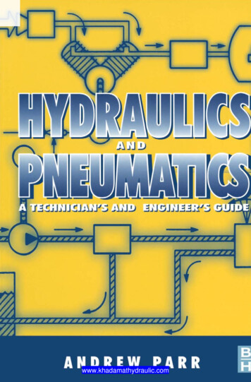
Hydraulics and PneumaticsA technician's and engineer's guideSecond editionA n d r e w Parr MSc., CEng., MIEE, MlnstMC EI NOXFORD BOSTON JOHANNESBURGEMANNMELBOURNE NEW DELHI com
Butterworth-Heinemann is an imprint of ElsevierLinacre House, Jordan Hill, Oxford OX2 8DP, UK30 Corporate Drive, Suite 400, Burlington, MA 01803, USAFirst edition 1991Reprinted 1992, 1993, 1995Second edition 1998Paperback edition 1999Reprinted 2000 (twice), 2002, 2003, 2004, 2005 (twice), 2006Copyright 9 1991, 1998, Andrew Parr. Published by Elsevier Ltd. All rights reservedThe right of Andrew Parr to be identified as the author of this work has beenasserted in accordance with the Copyright, Designs and Patents Act 1988No part of this publication may be reproduced, stored in a retrieval systemor transmitted in any form or by any means electronic, mechanical, photocopying,recording or otherwise without the prior written permission of the publisherPermissions may be sought directly from Elsevier's Science & Technology RightsDepartment in Oxford, UK: phone: ( 44) (0) 1865 843830; fax: ( 44) (0) 1865 853333;email: permissions@elsevier.com. Alternatively you can submit your request online byvisiting the Elsevier web site at http://elsevier.com/locate/permissions, and selectingObtaining permission to use Elsevier materialNoticeNo responsibility is assumed by the publisher for any injury and/or damage to personsor property as a matter of products liability, negligence or otherwise, or from any useor operation of any methods, products, instructions or ideas contained in the materialherein. Because of rapid advances in the medical sciences, in particular, independentverification of diagnoses and drug dosages should be madeBritish Library Cataloguing in Publication DataParr, E. A. (Eric Andrew)Hydraulics and pneumatics: a technician's and engineer's guide. - 2nd ed.1. Hydraulics 2. Hydraulic engineering 3. PneumaticsI. Title621.5'1Library of Congress Cataloging-in-Publication DataParr, E. A. (E. Andrew)Hydraulics and pneumatics: a technician's and engineer's guideAndrew Parr. 2nd ed.p. cm.Includes index1. Hydraulic machinery - Handbooks, manuals, etc. 2. PneumaticMachinery- Handbooks, manuals, etc. I. TitleTJ840.P2798-22010621.5' 419-2For information on all Butterworth-Heinemann publicationsvisit our website at books.elsevier.comPrinted and bound in Great Britain06 07 08 09 10 10 9ArtimaHydraulic.comwww.khadamathydraulic.com
Contents/xP refa c e1 Fundamental principlesIndustrial prime moversA brief system comparisonAn electrical systemA hydraulic systemA pneumatic systemA comparisonDefinition of termsMass and forcePressureWork, energy and powerTorque79111416Pascal's law17Pressure measurement21Fluid flow23TemperatureTemperature scalesTemperature measurement282829Gas laws31ArtimaHydraulic.comwww.khadamathydraulic.com
viContents2 Hydraulic pumps and pressure regulation34Pressure regulation39Pump typesGear pumpsVane pumpsPiston pumpsCombination pumps4242454650Loading valves51Filters523 Air compressors, air treatment and pressure regulation56Compressor typesPiston compressorsScrew compressorsRotary compressorsDynamic compressors5960636466Air receivers and compressor control67Air treatmentStages of air treatmentFiltersAir dryersLubricators7072727376Pressure regulationRelief valvesNon-relieving pressure regulatorsRelieving pressure regulators78798080Service units834 Control valves84Graphic symbols87Types of control valvePoppet valvesSpool valvesRotary valves90909296Pilot-operated om
ContentsviiCheck valvesPilot-operated check valvesRestriction check valves98101103Shuttle and fast exhaust valves106Sequence valves107Time delay valves108Proportional valves109Servo valves122Modular valves and manifolds125Cartridge logic valves1261305 ActuatorsLinear actuatorsConstructionMounting arrangementsCylinder dynamics130135140140Seals143Rotary actuatorsConstructional details146149Application notesSpeed controlActuator synchronisationRegenerationCounterbalance and dynamic brakingPilot-operated check valvesPre-fill and compression reliefBellows actuator1521521561601601621631666 Hydraulic and pneumatic accessories167Hydraulic reservoirs167Hydraulic accumulators169Hydraulic coolers and heat rechangers174Hydraulic fluids175Pneumatic piping, hoses and ulic.com
ContentsviiiHydraulic piping, hosing and connections7 Process control pneumatics183185Signals and standards186The flapper-nozzle188Volume boosters190The air relay and the force balance principle191Pneumatic controllers193Process control valves and actuators197198201204Flow control valvesActuatorsValve positionersConvertersI-P convertersP-I convertersSequencing applications8 Safety, fault-finding and ault-finding instruments222Fault-finding224Preventive mathydraulic.com
PrefaceMachines should work, people should thinkThe IBM Pollyanna PrinciplePractically every industrial process requires objects to be moved,manipulated or be subjected to some form of force. This is generallyaccomplished by means of electrical equipment (such as motors orsolenoids), or via devices driven by air (pneumatics) or liquids(hydraulics).Traditionally, pneumatics and hydraulics are thought to be amechanical engineer's subject (and are generally taught as such incolleges). In practice, techniques (and, more important, the faultfinding methodology) tend to be more akin to the ideas used in electronics and process control.This book has been written by a process control engineer as aguide to the operation of hydraulic and pneumatics systems. It isintended for engineers and technicians who wish to have an insightinto the components and operation of a pneumatic or hydraulicsystem. The mathematical content has been deliberately kept simplewith the aim of making the book readable rather than rigorous. It isnot, therefore, a design manual and topics such as sizing of pipesand valves have been deliberately omitted.This second edition has been updated to include recent developments such as the increasing use of proportional valves, andincludes an expanded section on industrial safety.Andrew ParrIsle of Sheppeyea parr @compuserve, comArtimaHydraulic.comwww.khadamathydraulic.com
This Page Intentionally Left BlankArtimaHydraulic.comwww.khadamathydraulic.com
IFundamental principlesIndustrial prime moversMost industrial processes require objects or substances to be movedfrom one location to another, or a force to be applied to hold, shapeor compress a product. Such activities are performed by PrimeMovers; the workhorses of manufacturing industries.In many locations all prime movers are electrical. Rotarymotions can be provided by simple motors, and linear motion canbe obtained from rotary motion by devices such as screw jacks orrack and pinions. Where a pure force or a short linear stroke isrequired a solenoid may be used (although there are limits to theforce that can be obtained by this means).Electrical devices are not, however, the only means of providingprime movers. Enclosed fluids (both liquids and gases) can also beused to convey energy from one location to another and, consequently, to produce rotary or linear motion or apply a force. Fluidbased systems using liquids as transmission media are calledhydraulic systems (from the Greek words hydra for water and aulosfor a pipe; descriptions which imply fluids are water although oilsare more commonly used). Gas-based systems are called Pneumaticsystems (from the Greek pneumn for wind or breath). The mostcommon gas is simply compressed air. although nitrogen is occasionally used.The main advantages and disadvantages of pneumatic orhydraulic systems both arise out of the different characteristics oflow density compressible gases and (relatively) high m
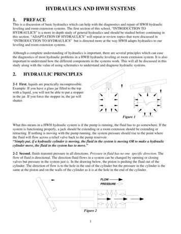
2Hydraulics and Pneumaticsincompressible liquids. A pneumatic system, for example, tends tohave a 'softer' action than a hydraulic system which can be proneto producing noisy and wear inducing shocks in the piping. Aliquid-based hydraulic system, however, can operate at far higherpressures than a pneumatic system and, consequently, can be usedto provide very large forces.To compare the various advantages and disadvantages of electrical pneumatic and hydraulic systems, the following three sectionsconsider how a simple lifting task could be handled by each.A brief system comparisonThe task considered is how to lift a load by a distance of about500 mm. Such tasks are common in manufacturing industries.An electrical systemWith an electrical system we have three basic choices; a solenoid, aDC motor or the ubiquitous workhorse of industry, the AC induction motor. Of these, the solenoid produces a linear stroke directlybut its stroke is normally limited to a maximum distance of around100 mm.Both DC and AC motors are rotary devices and their outputs need to be converted to linear motion by mechanical devicessuch as wormscrews or rack and pinions. This presents no realproblems; commercial devices are available comprising motor andscrew.The choice of motor depends largely on the speed controlrequirements. A DC motor fitted with a tacho and driven by athyristor drive can give excellent speed control, but has high maintenance requirements for brushes and commutator.An AC motor is virtually maintenance free, but is essentially afixed speed device (with speed being determined by number ofpoles and the supply frequency). Speed can be adjusted with a variable frequency drive, but care needs to be taken to avoid overheatingas most motors are cooled by an internal fan connected directly to themotor shaft. We will assume a fixed speed raise/lower is required, soan AC motor driving a screwjack would seem to be the ulic.com
Fundamental principles3Neither type of motor can be allowed to stall against an end oftravel stop, (this is not quite true; specially-designed DC motors,featuring good current control on a thyristor drive together with anexternal cooling fan, c a n be allowed to stall), so end of travel limitsare needed to stop the drive.We have thus ended up with the system shown in Figure 1.1 comprising a mechanical jack driven by an AC motor controlled by areversing starter. Auxiliary equipment comprises two limit switches, and a motor overload protection device. There is no practicalload limitation provided screw/gearbox ratio, motor size and contactor rating are correctly calculated.RaiseII .II3 ,,,V ' - - - - 415- - r .J OvedoadLowerRaise--o-13"LowerLS1Lower [ l RaiseLS2 --o'-' Raise I"-] Io--t pI i Lower(a) Electriccircuit ElectricmotorLS1Top limit switchLS2o- Bottom limit switchScrewjack(b) Physical layoutFigure 1.1Electrical solution, based on three phase motorArtimaHydraulic.comwww.khadamathydraulic.com
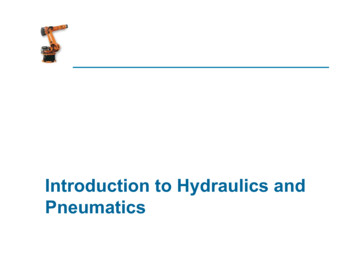
4Hydraulics and PneumaticsA hydraulic systemA solution along hydraulic lines is shown in Figure 1.2. A hydrauliclinear actuator suitable for this application is the ram, shownschematically in Figure 1.2a. This consists of a movable piston connected directly to the output shaft. If fluid is pumped into pipe A thepiston will move up and the shaft will extend; if fluid is pumpedinto pipe B, the shaft will retract. Obviously some method ofretrieving fluid from the non-pressurised side of the piston must beincorporated.The maximum force available from the cylinder depends on fluidpressure and cross sectional area of the piston. This is discussedfurther in a later section but, as an example, a typical hydraulicpressure of 150 bar will lift 150 kg cm -2 of piston area. A load of2000 kg could thus be lifted by a 4.2cm diameter piston.A suitable hydraulic system is shown in Figure 1.2b. The systemrequires a liquid fluid to operate; expensive and messy and, consequently, the piping must act as a closed loop, with fluid transferredfrom a storage tank to one side of the piston, and returned from theother side of the piston to the tank. Fluid is drawn from the tank bya pump which produces fluid flow at the required 150 bar. Suchhigh pressure pumps, however, cannot operate into a dead-end loadas they deliver constant volumes of fluid from input to output portsfor each revolution of the pump shaft. With a dead-end load, fluidpressure rises indefinitely, until a pipe or the pump itself fails. Someform of pressure regulation, as shown, is therefore required to spillexcess fluid back to the tank.Cylinder movement is controlled by a three position changeovervalve. To extend the cylinder, port A is connected to the pressureline and port B to the tank. To reverse the motion, port B is connected to the pressure line and port A to the tank. In its centre position the valve locks the fluid into the cylinder (thereby holding it inposition) and dead-ends the fluid lines (causing all the pump outputfluid to return to the tank via the pressure regulator).There are a few auxiliary points worthy of comment. First, speedcontrol is easily achieved by regulating the volume flow rate to thecylinder (discussed in a later section). Precise control at low speedsis one of the main advantages of hydraulic systems.Second, travel limits are determined by the cylinder stroke andcylinders, generally, can be allowed to stall at the ends of travel sono overtravel protection is com
Fundamental principlesAi;,,5wBRaise(a) Hydraulic cylinder/t/,'t//,I'//\Electric//('M)FilterH ]-\motor\\\"',HI , t %2,,PumpII/ /Pressureregulation xoe IrOffRaise q 9 9 Lower\\"\, "'. g,.?;;J.!fC,I f /w\ I1 NEdva've 'IIIL . . . . . . . . . . . . . . . . . . . .II - Components commonJ to many motions(b) Physical componentsFigure 1.2Hydraulic solutionThird, the pump needs to be turned by an external power source;almost certainly an AC induction motor which, in turn, requires amotor starter and overload protection.Fourth, hydraulic fluid needs to be very clean, hence a filter isneeded (shown in Figure 1.2b) to remove dirt particles before thefluid passes from the tank to the pump.ArtimaHydraulic.comwww.khadamathydraulic.com
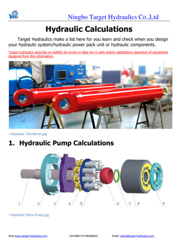
6Hydraulics and PneumaticsOne final point worth mentioning is that leaks of fluid from thesystem are unsightly, slippery (hence hazardous) and environmentally very undesirable A major failure can be catastrophic.At first sight Figure 1.2b appears inordinately complicated compared with the electrical system of Figure 1.1, but it should beremembered all parts enclosed in the broken-lined box in Figure 1.2are common to an area of plant and not usually devoted to just onemotion as we have drawn.A pneumatic systemFigure 1.3 shows the components of a pneumatic system. The basicactuator is again a cylinder, with maximum force on the shaft beingdetermined by air pressure and piston cross sectional area.Operating pressures in pneumatic systems are generally muchlower than those in a hydraulic systems; 10 bar being typical whichwill lift 10 kg cm -2 of piston area, so a 16 cm diameter piston isrequired to lift the 2000 kg load specified in the previous section.Pneumatic systems therefore require larger actuators than hydraulicsystems for the same load.The valve delivering air to the cylinder operates in a similar wayto its hydraulic equivalent. One notable difference arises out of thesimple fact that air is free; return air is simply vented to atmosphere.lIII -'FilterI. 'r i ' k --,,,I1'V -'l[t II ',IIi:1I[II CompressoPSI3"-' Opens when/pressure reachedHAir coolerand airtreatmentrElettrr'c]I OffI Raise Lower.Storage i ( ? ?/ reservoir I /\ I B I]Pressure.i[1 c 176176U PSII1II Exhaustsw,tcn. . . . . .IJI1 valveComponents commonto more than one motioniL . . . . . . . . . . . . . . . . . . . . . . . . . .Figure1.3.1Pneumatic om
Fundamental principles7Air is drawn from the atmosphere via an air filter and raised torequired pressure by an air compressor (usually driven by an ACmotor). The air temperature is raised considerably by this compressor. Air also contains a significant amount of water vapour. Beforethe air can be used it must be cooled, and this results in the formation of condensation So, the air compressor must be followed by acooler and air treatment unit.Compressibility of a gas makes it necessary to store a volume ofpressurised gas in a reservoir, to be drawn on by the load. Withoutthis reservoir, a slow exponential rise of pressure results in a similarslow cylinder movement when the valve is first opened. The airtreatment unit is thus followed by an air reservoir.Hydraulic systems require a pressure regulator to spill excessfluid back to the tank, but pressure control in a hydraulic system ismuch simpler. A pressure switch, fitted to the air reservoir, starts thecompressor motor when pressure falls and stops it again when pressure reaches the required level.The general impression is again one of complexity, but units inthe broken-lined box are again common to one plant or even awhole site. Many factories produce compressed air at one centralstation and distribute an air ring main to all places on the site in asimilar way to other services such as electricity, water or gas.A comparisonTable 1.1 gives superficial comparisons of the various systems discussed in the previous sections.Definition of termsThere is an almost universal lack of standardisation of units used formeasurement in industry, and every engineer will tell tales of gaugesindicating, say, velocity in furlongs per fortnight. Hydraulics andpneumatic systems suffer particularly from this characteristic, and itis by no means unusual to find pressure indicated at different locations in the same system in bar, kpascal and psi.There is, however, a welcome (and overdue) movement to standardisation on the International System (SI) of units, but it will besome time before this is complete. The engineer will thereforeencounter many odd-ball systems in the years to come.ArtimaHydraulic.comwww.khadamathydraulic.com
8Hydraulics and PneumaticsTable 1.1systemsComparisons of electrical, hydraulic and pneumaticElectricalHydraulicPneumaticEnergy sourceUsually fromoutside supplierElectric motor ordiesel drivenElectric motor ordiesel drivenEnergy storageLimited (batteries)Limited(accumulator)Good (reservoir)DistributionsystemExcellent, withminimal lossLimited basicallya local facilityGood. can betreated as a plantwide serviceEnergy costLowestMediumHighestRotary actuatorsAC & DC motors.Good control onDC motors. ACmotors cheapLow speed. Goodcontrol. Can bestalledWide speed range.Accurate speedcontrol difficultLinear actuatorShort motion viasolenoid.Otherwise viamechanicalconversionCylinders. Veryhigh forceCylinders.Medium forceControllable highforceControllablemedium forceLeakagedangerous andunsightly. FirehazardNoiseControllable force Possible withsolenoid & DCmotorsComplicated byneed for coolingPoints to noteDanger fromelectric shockAny measurement system requires definition of the six units usedto measure: 99999length"mass;time;temperature;electrical current;light intensity.Of these, hydraulic/pneumatic engineers are primarily concernedwith the first three. Other units (such as velocity, force, com
Fundamental principles9can be defined in terms of these basic units. Velocity, for example,is defined in terms of length/time.The old British Imperial system used units of foot, pound andsecond (and was consequently known as the fps system). Earlymetric systems used centimetre, gramme and second (known as thecgs system), and metre, kilogramme and second (the mks system).The mks system evolved into the SI system which introduces amore logical method of defining force and pressure (discussed inlater sections). Table 1.2 gives conversions between basic simpleunits.Table 1.2Fundamental mechanical unitsMass1 kg 2.2046 pound (lb) 1000 gm1 lb 0.4536 kg1 ton (imperial) 2240 lb 1016 kg 1.12 ton (US)1 tonne - 1000 kg 2204.6 lb 0.9842 ton (imperial)1 ton (US) 0.8929 ton (imperial)Length1 metre - 3.281 foot (ft) - 1000 mm - 100 cm1 i n c h - 25.4 m m - 2.54 cm1 yard - 0.9144 mgolum#1 l i t r e - 0.2200 gallon (imperial)- 0.2642 gallon (US)1 gallon ( i m p e r i a l ) - 4.546 l i t r e - 1.2011 gallon (US) 0.161 cubic ft1 gallon ( U S ) - 3.785 l i t r e - 0.8326 gallon (imperial)1 cubic m e t e r - 220 gallon (imperial) 35.315 cubic feet1 cubic i n c h - 16.387 cubic centimetresMass and forcePneumatic and hydraulic systems generally rely on pressure in afluid. Before we can discuss definitions of pressure, though, wemust first be clear what is meant by everyday terms such as weight,mass and force.ArtimaHydraulic.comwww.khadamathydraulic.com
10Hydraulics and PneumaticsWe all are used to the idea of weight, which is a force arisingfrom gravitational attraction between the mass of an object and theearth. The author weighs 75 kg on the bathroom scales; this isequivalent to saying there is 75 kg force between his feet and theground.Weight therefore depends on the force of gravity. On the moon,where gravity is about one sixth that on earth, the author's weightwould be about 12.5 kg; in free fall the weight would be zero. In allcases, though, the author's mass is constant.The British Imperial fps system and the early metric systems linkmass and weight (force) by defining the unit of force to be the gravitational attraction of unit mass at the surface of the earth. We thushave a mass defined in pounds and force defined in pounds force(lbs f) in the fps system, and mass in kilogrammes and force inkg f in the mks system.Strictly speaking, therefore, bathroom scales which read 75 kgare measuring 75 kg f, not the author's mass. On the moon theywould read 12.5 kg f, and in free fall they would read zero.If a force is applied to a mass, acceleration (or deceleration) willresult as given by the well known formula:F ma.(1.1)Care must be taken with units when a force F is defined in lbs f orkg f and mass is defined in lbs or kg, because resulting accelerationsare in units of g; acceleration due to gravity. A force of25 kg f applied to the author's mass of 75 kg produces an acceleration of 0.333 g.The SI unit of force, the newton (N), is defined not from earth'sgravity, but directly from expression 1.1. A newton is defined as theforce which produces an acceleration of 1 m s-2 when applied to amass of 1 kg.One kgf produces an acceleration of 1 g (9.81 ms -z) whenapplied to a mass of 1 kg. One newton produces an acceleration of1 ms -2 when applied to mass of 1 kg. It therefore follows that:1 kgf 9.81 Nbut as most instruments on industrial systems are at best 2% accurate it is reasonable (and much simpler) to use:lkgf 10Nfor practical applications.Table 1.3 gives conversions between various units of force.ArtimaHydraulic.comwww.khadamathydraulic.com
Fundamental principlesTable 1.311Units of force1 newton (N) - 0 . 2 2 4 8 pound force (lb f) 0.1019 kilogram force (kg f)1 lb f - 4.448N - 0.4534 kg f1 kg f - 9.81N - 2.205 lbOther units aredynes (cgs unit); 1 N - 105 dynesponds (gram force); 1 N - 102 pondsSI unit is the newton"N - k g ms -2PressurePressure occurs in a fluid when it is subjected to a force. In Figure1.4 a force F is applied to an enclosed fluid via a piston of area A.This results in a pressure P in the fluid. Obviously increasing theforce increases the pressure in direct proportion. Less obviously,though, decreasing piston area also increases pressure. Pressurein the fluid can therefore be defined as the force acting per unitarea, or:FP A"(1.2)Although expression 1.2 is very simple, there are many differentunits of pressure in common use. In the Imperial fps system, forexample, F is given in lbs f and A is given in square inches to givepressure measured in pound force per square inch (psi).IF P i s t o n area AFluid at p r e s s u r e P F/AFigure 1.4Pressure in a fluid subjected to a forceArtimaHydraulic.comwww.khadamathydraulic.com
12Hydraulics and PneumaticsIn metric systems, F is usually given in kgf and A in square centimetres to give pressure in kilogram/force per square centimetre (kgf cm-2).The SI system defines pressure as the force in newtons per squaremetre (N m-Z). The SI unit of pressure is the pascal (with 1 Pa 1 N m-Z). One pascal is a very low pressure for practical use,however, so the kilopascal (1 k P a - 1 0 3 p a ) or the megapascal(1 MPa 10 6 Pa) are more commonly used.Pressure can also arise in a fluid from the weight of a fluid. Thisis usually known as the head pressure and depends on the height offluid. In Figure 1.5 the pressure at the bottom of the fluid is directly proportional to height h.hi//////'/ Figure 1.5Pressure in fluid at base:P ph (psi or kg cm -2)P pgh pascalHead pressure in a fluidIn the Imperial and metric systems head pressure is given by:P - oh.(1.3)where p is the density and h the height (both in the correct units) togive P in psi or kg cm -2.In the SI system expression 1.3. is re-arranged as:P - pgh.(1.4)where g is the acceleration due to gravity (9.81 ms -2) to give thepressure in pascal.Pressure in a fluid can, however, be defined in terms of the equivalent head pressure. Common units are millimetres of mercury andcentimetres, inches, feet or metres of water. The suffix wg (forwater gauge) is often used when pressure is defined in terms of anequivalent head of water.We live at the bottom of an ocean of air, and are consequentlysubject to a substantial pressure head from the weight of air aboveArtimaHydraulic.comwww.khadamathydraulic.com
Fundamental principles13us. This pressure, some 15 psi, 1.05 kg f c m -2, or 101 kPa, is calledan atmosphere, and is sometimes used as a unit of pressure.It will be noted that 100 kPa is, for practical purposes, one atmosphere As this is a convenient unit for many applications 100 kPa(105 Pa or 0.1 MPa) has been given the name bar. Within theaccuracy of instrumentation generally found in industry 1 bar 1 atmosphere.There are three distinct ways in which pressure is measured,shown in Figure 1.6. Almost all pressure transducers or transmittersmeasure the pressure difference between two input ports. This isknown as differential pressure, and the pressure transmitter inFigure 1.6a indicates a pressure of P]-P2.In Figure 1.6b the low pressure input port is open to atmosphere,so the pressure transmitter indicates pressure above atmosphericpressure. This is known as gauge pressure, and is usually denotedby a g suffix (e.g. psig). Gauge pressure measurement is almost universally used in hydraulic and pneumatic systems (and has beenimplicitly assumed in all previous discussions in this chapter).P re ssu retransmitterPressuretransmitterelHiP1 P2LOLo"--'-OpentoatmosphereIndication (P1 - atmosphere)Indication (P1 - P2)(a) Differential pressure(b) Gauge pressurePressuretransmitterP,.i,1Lo "--"-- Hi/iiVacuumn-iIndication P1(c) Absolute pressureFigure 1.6Different forms of pressure c.com
14Hydraulics and heric0Figure 1.7. . . . . . . . . . . . . . . .VacuumRelationship between absolute and gauge pressuresFigure 1.6c shows the pressure transmitter measuring pressurewith respect to a vacuum. This is known as absolute pressure and isof importance when the compression of gases is considered. Therelationship between absolute and gauge pressure is illustrated inFigure 1.7. Pressure measurement and gas compression are discussed in later sections. Table 1.4 compares units of pressure. Atypical hydraulic system operates at 150 bar, while typical pneumatic systems operate at 10 bar.Work, energy and powerWork is done (or energy is transferred) when an object is movedagainst a force, and is defined as:work force x distance moved.(1.5)In the Imperial fps system expression 1.5 gives a unit of ft lb f. Formetric systems the unit is cm kg f. The SI unit of work is the joule,where 1 J - 1 N m ( 1 m 2 kg s-Z). Table 1.5 compares these, andother, units of work.Power is the rate at which work is performed:workpower - time"(1.6)The SI unit of power is the watt, defined as 1 J s-1. This is by far themost common unit of power, as it is almost universally used for themeasurement of electrical power.The Imperial system uses horse power (Hp) which was used historically to define motor powers. One horse power is defined as550 ft lb f s-1. Table 1.6 compares units of power.ArtimaHydraulic.comwww.khadamathydraulic.com
Fundamental principlesTable 1.4Units of pressure1 b a r - 100 kPa 14.5 psi 750 m m H g 401.8 inches W G 1.0197 k g f cm -2 0.9872 atmosphere1 kilopascal - 1000 Pa 0.01 bar 0.145 psi 1.0197 x 10 -3 kgf cm -2 4.018 inches W G 9.872 x 10 -3 atmosphere1 pound per square inch (psi) - 6.895 kPa 0.0703 k g f cm -2 27.7 inches W G1 kilogram force per square cm (kgf cm-2) - 98.07 kPa 14.223 psi1 A t m o s p h e r e - 1.013 bar 14.7 psi 1.033 kgf cm -2SI unit of pressure is the pascal (Pa) 1 P a - 1N m -2Practical units are the bar and the psi.Table 1.5Units of w o r k (energy)1 joule (J) 2.788 x 10 4 W h (2.788 x 1 0 .7 kWh)0.7376 ft lbf0.2388 calories9.487 x 10 4 British thermal units (BTu)0.102 kgf m 10 7 ergs (cgs unit)SI unit of w o r k is the joule (J)1J-1Nm 1 m 2 kg s -2ArtimaHydraulic.comwww.khadamathydraulic.com15
16Hydraulicsand PneumaticsTable 1.6Units of power1 kwatt ( k w ) - 1.34 Hp 1.36 metric Hp 102 kgf m s
4 Hydraulics and Pneumatics A hydraulic system A solution along hydraulic lines is shown in Figure 1.2. A hydraulic linear actuator suitable for this application is the ram, shown schematically in Figure 1.2a. This consists of a mov