Transcription
CHAPTER 2Pneumatics: Air Preparationand Componentsagvutem.wordpress.com
IntroductionThe use of air as an energy transfer medium can be trace back 2000years ago. Practical industrial application of pneumatics dates toaround 1950, when the demand for automation in industrial productionlines increased. Some desirable feature is pneumatics are: Stability under temperature changePneumatic actuator can be used in manufacturing plants wherehigh and low temperature are requiredCleanlinessLeak do not cause contaminationHigh speedCan control high speed actuatorOverload safetyTools can be loaded until they stall and are therefore overloadsafe
and some of the undesirable feature are: CompressibilityConstant actuator velocity is not possibleForce limitationLimited force load can be use under normal working pneumaticpressure compare to hydraulicFluid preparationDirt and humidity must be clean from air to prevent wear and tear ofpneumatic componentsCostCompress air is relatively expensive means of conveying powerPart of the cost disadvantages is offset by the fact that the pneumaticcomponent are inexpensive and can operate at a high number ofcycles per workday. Operating cost can be controlled by taking care toensure that leaks are minimized.
Properties of air Atmospheric air consists of 21% oxygen, 78 % nitrogen and 1% other. Italso contain 4% of water vapor. Water vapor varies constantly. Theatmospheric pressure is measure at 101 kPa at 20 C. Specific weight of airis 11.8N/m3 at atmospheric condition.Air isn’t only readily compressible, but its volume will vary to fill thevessel containing it because air molecule have substantial internal energy& are at a considerable distance from each other. Due to the sensitivity ofdensity changes with respect to change in pressure & temperature.Free air is consider to be air at actual atmospheric condition. Sinceatmospheric pressure and temperature varies from day to day, thecharacteristic of free air varies accordingly. Thus when making pneumaticcircuit calculations, the term standard air is used. Standard air sea levelair having the temperature at 20C and pressure at 101kPa andrelative humidity at 36%.Absolute pressure (Pa) gage pressure (Pa) 101,000 PaAbsolute temperature (K) temperature ( C) 273
Overview on pneumatic concept
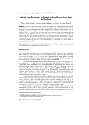
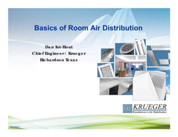
continuedDryerCompressorFRL Unit(filter regulatorAir gure 2.1 : the block diagram for pneumatic systemcomponent
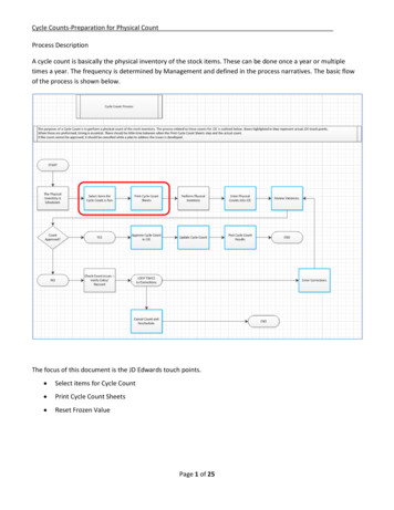
Air preparation and components In air preparation, it will involved component such as compressor, dryer,receiver and FRL unit, as illustrated in Figure 2.2. These are the essentialcomponents that make up a stable and reliable pneumatic system.
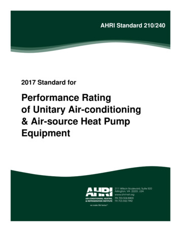
continuedFigure 2.2 :Air generation and distribution
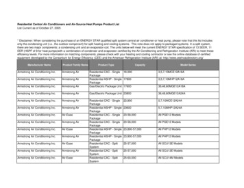
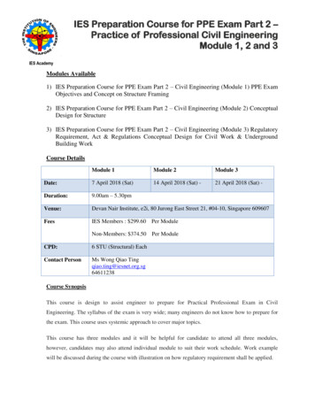
continuedFigure 2.3 : Typical Pneumatic system
The perfect gas laws During the sixteenth century, scientists discovered the laws thatdetermine the interaction of pressure, volume and temperature ofgas.These laws are called the “perfect gas laws” because they werederived in the basis of a perfect gas. Even though perfect gasdoes not exist, air behaves very closely to that predicted by theseperfect gas law’s.The perfect gas laws consist from Bolye’s Law, Charles’s Lawand guy Lussac’s Law. All of the above combine it is call thegeneral gas law or ideal gas law.
Gas LawSince gases are used in pneumatic systems it is important tomention at least some of the basic behavioral of such gases; Boyle’s Law state that if the temperature of a given amount of gas isheld constant the relationship between volume and pressure can becalculated from below equationP1 V1 P2 V2
continued Charles’s Law state that if the pressure of a given amount of gas is heldconstant the relationship between volume and temperature can becalculated from below equation ;V1 T2 V2 T1
continued Guy Lussac’s Law state that if the volume of a given amount of gas is heldconstant the relationship between temperature and pressure can becalculated from below equation ;P1 T2 P2 T1
Perfect gas law General Gas Law (Ideal Gas Law) state that if the volume of a givenamount of gas is held constant the relationship between temperature andpressure can be calculated from below equation ;P1 V1 T2 P2 V2 T1
The Perfect Gas LawsBolye’s lawBolye’s Law: If the temperature of agiven amount of gas is held constant,the relationship between volume andpressure can be calculated by:P1V1 P2V2Gay-Lussac’s lawGuy Lussac’s Law: If the volume of agiven amount of gas is held constantthe relationship between temperatureand pressure can be calculated by:P1 T1 P2 T2Charles’s LawCharles’s Law: If the pressure of agiven amount of gas is held constantthe relationship between volume andtemperature can be calculated by:V1 T1 V2 T2General gas law (Ideal Gas Law)The general gas law contain all three gasparameters (pressure, temperature andvolume), since none are held constantduring a process from state 1 to state 2p1V1 p2V2 T1T2
The Perfect Gas LawsExample:Gas at 70 bars gage pressure and 37.8C is container in a 12,900 cm cylinder. Apiston compresses the volume to 9,680 cm while the gas is heated to 93.3C.What is the final pressure in the cylinder?p1V1 p2V2 T1T2p1V1T2 (70 105 1 105 )(12,900)(93.3 273)p2 V2T1(9680)(37.8 273) 111.5 105 Pa (abs)
Force transmissionWhen one end of solid bar isstruck, the main force of the blowis transmitted straight through thebar to the opposite end.Figure 2.6 Transmissionof force through a solidmaterial and through astatic fluidWhen a force is applied to the endof a column of confined liquid, theforce is transmitted straight to itsopposite and equally andundiminished -in every otherdirection.
Transmission of force by fluidsPascal Law states that pressureapplied to as static and confinedfluid transmitted undiminished inall directions and acts with equalforce on equal areas at right anglesto themFigure 2.7 : Pascal’ law
continued Blaise Pascal (1623-1662) discovered thatpressure is equal to force per unit area, or theforce divided by the area on which it acts. From Pascal’s Law, there are three importantquantities such as Force, Pressure and Area.Figure 2.7 illustrates Pascal’s Law.
Force Force cannot be seen but their effects can be.A force applied to an object has the effect ofcausing:i) a movement to begin or change; or ii)the shape of an object to change. In pneumatic application, force is produced byan air pressure acting onto a surface (usually apiston, a valve or a diaphragm as illustrated inFigure 2.8.
Pressure Pressure is defined as force per unit area asillustrated in Figure 2.9. This means that if wewant to find out the pressure required for acertain pneumatic application, we have tomeasure or determine two quantities such as:i) the size of force required. ii) the area over which the pressure is acting.
Area The only area that is important is the surface on which the pressurecan act that will produced the force required for the job. This area iscalled effective area where it can be in terms of square or circular. Byusing these three quantities such as Force, Pressure and Area, therelationship can be defined as:ForcePressure Area The effective area on which pneumatic pressure can act to producethe required pneumatic force is either the projection of ball seatarea, the projection of the pressure exposed piston area orcalculated effective piston area.
Quantities and UnitsTable 2.1 Basic Units
continuedTable 2.2 : Derived units
Pneumatic Components
Pneumatic: Compressor A compressor is a machine that compresses air or another type ofgas from low inlet pressure usually atmospheric pressure to highdesired pressure level.This is accomplish by reducing the volume of the gas. There arevarious type of compressor design that are used in industries.Some of the most widely used are piston type, rotary screw typeand vane type.Type of compressorPositive - displacementOperate by opening up acavity to draw in fluid, thenclose the cavity to expel thefluid. ie: gear, vane, pistonNon positive - displacementOperate by imparting avelocity to the fluid. ie:centrifugal type
Piston TypeCompressor Capable of providingpressure up to 150 psi.Higher than that willresult in in efficiencypumping action due tocompression chambersize & heat ofcompression.
Screw Type Compressor Compression is accomplished by rolling the trapped air into aprogressively smaller volume as the screw rotate.Unsymmetrical profile of rotors would eliminate wear throughelimination of metal-to-metal contact.Precisely measured amount of filtered & cooled air is injected intocompression chamber.
Vane Type Compressor Cylindrical slotted rotor turns inside of a stationary outer casing.Each rotor slot contains a rectangular vane, which slides in and outdue to centrifugal force. As rotor turns, air is trapped & compressedbetween the vanes & then discharged through a port to thereceiver.Able to operate up to approximately 50 psi in a single stage & up to150 psi in a 2-stage design.
Air Capacity Rating of a CompressorSizing of Air Receiver / ReservoirPower Required to Drive CompressorAir Capacity Rating of a Compressor Air compressors are rated in term of cfm of free air, defined as airat actual atmospheric condition.Cfm of free air is called scfm when the compressor inlet air is at thestandard atmospheric conditions.Equation used in determine the rating is:P and T values refer to absolute pressure & temperature values.
Sizing of Air Receiver / Reservoir Parameters involved in sizing of air receiver: Pressure Flow-rate requirements Compressor output capability Type of operationsFunctions of a receiver: To supply air at an essentially constant pressure. To dampen pressure pulses either coming from the compressoror the system during valves shifting and operations.Equation used:
Power Required to Drive Compressor Equation used to determine power required to drive an aircompressor to meet system pressure & flow-rate requirements: To determine the actual power, theoretical horsepower is dividedby the overall compressor efficiency, o
Fluid ConditionersMain purpose: to make air a more acceptable fluid medium for apneumatics system as well as operating personnel.Air FilterMain function: toremove contaminantsfrom air before itreaches pneumaticscomponentsPressure RegulatorMain function: toprovide a constantpressure for a givenpneumatics systemAir LubricatorMain function: to ensure properlubrication of internal movingparts of pneumatics componentsMuffler / Exhaust SilencerMain function: to control the noisecaused by a rapidly exhasutingairstream flowing into atmosphereAftercoolerMain functions: to cool the hot airdischarged & remove most of the moisturefrom air discharged by compressorAir DryerMain function: to remove enough moisture from air so that air willnot become saturated as it flow through pneumatics system
Fluid ConditionersAir Pressure RegulatorAir Filter
Fluid ConditionersIndividual Filter, Regulator,Lubricator UnitsAir Lubricator
Fluid Conditioners
Air Flow Rate Control With Orifices It is important to evaluate the flow-rate of air through an orifice.Such a relationship is discussed for hydraulic system. However,because of the compressibility of air, the relationship describing theflow-rate of air is more complex. Equation used provides the calculation of air volume flow-ratesthrough orifices:Q 22.7CV( p1 p2 )( p2 )T1 Note that the equation is valid when p2 is more than 0.53p1.Beyond this region, flow through the orifices is said to be choked. Values of Cv are determined by valve manufacturers & are usuallytabulated for various sizes of valves.
Air Control ValvesCheck ValveShuttle Valve
Directional Control Two-Way Valve
Flow Control Valve Spring-loaded disk allows free flow in one direction & adjustable /controlled flow in opposite direction. Flow adjustment is performed by a tapered brass stem that controlsthe flow through the cross hole in the disk.
Pneumatics Actuators Due to the air as fluid medium rather than liquid, pressures applied inthe system are lower, and hence pneumatic actuators are of lighterconstruction.
Air Requirements of Pneumatics Actuators
Sizing of Air Receiver / Reservoir Parameters involved in sizing of air receiver: Pressure Flow-rate requirements Compressor output capability Type of operations Functions of a receiver: To supply air at an essentially constant pressure. To dampen pressure pulses either coming from the compressor or the system during valves shifting and operations. Equation used .