Transcription
ISSN 2466-2232 (Print)ISSN 2466-2100 (Online)Study on the Mechanism of Nugget Growth Behaviorin Three Sheets Stack Resistance Spot WeldingNazmul Huda*, Dae-Geun Nam** and Yeong-Do Park***,†*Department of Mechanical and Mechatronics Engineering, University of Waterloo, Waterloo,Ontario, N2L 3G1, Canada**Dongnam Regional Division, Korea Institute of Industrial Technology, Busan, 46742, Korea***Department of Advanced Materials Engineering, Dong-Eui University, Busan, 47340, Korea†Corresponding author : ypark@deu.ac.kr(Received December 1, 2019 ; Revised December 5, 2019 ; Accepted December 16, 2019)AbstractThe present study focused on finding a mechanism to achieve good weldability in three sheets spot welding.Two combinations of three sheets (Al-HPF combinations with mild steel / HPF steel / DP steel stacking)and (TRIP combination with mild steel / TRIP780 steel / DP590 steel stacking) were used. Weld qualitywas evaluated by measuring the button diameter after peel test, and peak load measurement using a tensileshear test. A high speed camera and simulation (SORPAS) were used to investigate the nugget growthmechanism. The Al-HPF combinations showed higher nugget growth rate in the sheet thickness direction,however the TRIP combination showed higher nugget growth rate in the sheet rolling direction. Also, theTRIP combination produced a larger nugget diameter (or higher penetration) in the thin sheet of interface"A" than the Al-HPF combination. The main reason for the larger nugget diameter in the TRIP combinationwas the higher current density and wider current path resulting from the high indentation on interface "A".The selection of a middle sheet with optimum electro-mechanical properties for the three sheet stack canimprove the weldability of three sheets spot welding for car body construction.Key Words : Resistance spot welding, Three sheets stack spot welding, Tensile shear strength, Nugget growth,Current density, Nugget diameter1. IntroductionThree sheets spot welding is more complicated compared to two sheets spot welding as nugget needs to beformed in all three sheets. Different types of similar anddissimilar combination of three sheets spot welding arecurrently applied in some complex structure of automobile body such as front longitudinal rails, A, B, C- pillars and the bulk head to inner ring1). The complicationinvolved in three sheets spot welding is nugget growthin a thin sheet. If one of the external sheet is thinnerthan the other two sheets, the interface between thin andthe middle sheet is located closer to the electrode. Highcooling occurs by electrode water circulation in this interface compared to thick-thick interface. If the heat in-put is low, this might not be sufficient for nugget formation in thin-thicker sheet interface. At high heat input, nugget may form in thin-thick sheet interface butmight cause expulsion in thick-thick sheet interface.The introduction of the coating layer, surface quality,and alignment make three sheets spot welding morecomplicated. Methods, like the use of different sizeelectrodes in two sides of sheets, use of process tape ofproper resistance2), forging force3) and use of shuntingmethod4) have been studied by several authors. All themethods mentioned above, the purpose is to make heatbalance between two interfaces of sheets and therebyhelping nugget formation in the thinner sheet and alsoreduce the probability of expulsion in thick-thick sheetinterface. However, these methods are not easily applicable currently in all industries. Therefore, researchersJournal of Welding and Joining, Vol.37 No.6(2019) pp564-571https://doi.org/10.5781/JWJ.2019.37.6.5
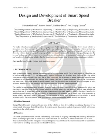
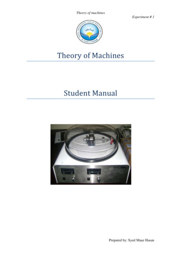
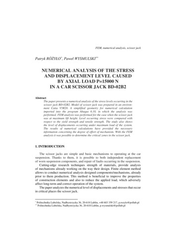
Study on the Mechanism of Nugget Growth Behavior in Three Sheets Stack Resistance Spot Welding2. MaterialsIn this study, two combinations [(GA SGARC (0.7t) Al-HPF (1.2t) DP 590 (1.4t)) and (GA SGARC (0.7t) TRIP 780 (1.2t) DP 590 (1.4t))] of three sheets oftotal thickness 3.30 mm was used for welding withkeeping top and bottom sheet constant. In the followingsections, the two combinations will abbreviated as AlHPF combination and TRIP combination respectively,where the top sheet is GA SGARC and the bottom sheetis DP590. The GA SGARC having galvannealed coating layer of thickness 11 µm. In the Al-HPF combinations, the middle sheet was Al-HPF which having Al-Sicoating layer of 32 µm thickness. The chemical composition of Al-HPF contains 0.23% carbon, 0.26% silicon,1.24% Mn, etc. However, for TRIP combinations, themiddle sheet was cold-rolled TRIP 780.Its chemicalcom- position consists of 0.099% carbon, 1.35% silicon, 2.35% Mn, etc. The bottom sheet DP 590 was alsocold rolled.3. Welding Equipment and ProcedurePedestal type AC welding controller was used to perform the multiple sheets welding. The sheets dimensionwas 100 mm 30 mm (length x width) and weldingwas performed according to the setup shown in Fig. 1.Electrode force of 3.5 kN, squeeze time 70 cycle,Single pulse of 21 cycles weld time and 15 cycles ofhold time were set during welding. Dome radius typeCu-Cr electrode of 6.0 mm diameter was used forwelding. Tensile shear tests (TST) were carried out in auniversal tensile test machine of load capacity 100 kNDiameter ATop sheet(0.7t)Interface APenetration Aby pulling a thin sheet apart from two high strengthsteels. The acceptable weld current range was determinedbased on attaining a minimum button diameter of 3.30mm in interface A (thin-thick sheet interface) after thetensile test. The dynamic resistance and expulsion criteria were monitored by the dynamic resistance measuring system. Expulsion conditions were confirmed byobserving dynamic resistance during welding. For metallographic analysis, nugget growth and the bondingmechanism was monitored by stereomicroscope and optical microscope Olympus BX51M. The microstructureof the welded parts were revealed by using picral etchant (1% HCl, 3% picral and 96% ethanol). For highspeed camera video, the experimental schedule used is1.75 kN electrode force, welding current 3.0 kA andweld time 21 cycles with half-cut electrode on both sides.All the value is chosen half of the actual welding exceptthe weld time for better imaging of heat generation andmelting. The frame rate of high speed camera is set2000 frame/second with a shutter speed 1/4000 sec.4. Results and Discussion4.1 Weld growth curveThe weld quality of three sheets spots welding can beinspected by button diameter in interface “A” after thetensile test. In the purpose of gaining a good weldabilitynugget must be formed in thin sheet. The resistancespot welding usually consists of interfacial fracture, partial interfacial fracture and button fracture. Button fracture is defined based on gaining a minimum button diameter of 3.30 mm in interface “A” after the tensiletest. The welding current is varied from 5.0 kA to 10.5kA with 0.5 kA increment. Based on minimum buttondiameter in interface “A”, Al-HPF combinations havinga weldable current range of 3.0 kA while TRIP combinations are having 2.5kA (Fig. 2). At 6.0 kA Al-HPF10.0HPF combinationsTRIP combinations8.0Button dia (mm)have to rely on varying the weld time, weld current,electrode force, pulsing system and material combinations.The present study focused on finding a mechanism toachieve improved weld quality (or larger nugget diameter) in three sheets spot welding by observing and comparing the heat generation and nugget growth of twodifferent combinations of three sheets stacking.6.02.5 kA4.03.30 mm3.0 kA2.0Middle sheet (1.2t)Penetration BBottom sheet(1.4t)Interface BDiameter BFig. 1 Schematic of three sheets stack resistance spotwelded tensile test specimen대한용접․접합학회지 제37권 제6호, 2019년 12월0.04.05.06.07.08.09.010.011.0Weld current(kA)Fig. 2 Button diameter on interface “A” with increasingresistance spot welding current for hot pressforming steel and TRIP steel combinations565
Nazmul Huda, Dae-Geun Nam and Yeong-Do Parkshows a partial interfacial fracture but TRIP combination shows a fully interfacial fracture. Both the Al-HPFand TRIP combination shows a satisfactory button(3.30 mm) formation initiation at 6.5 kA. the TRIPcombinations possess a higher button diameter in allwelding current after 6.0 kA, except the expulsion conditions due to higher heat generation caused by jouleheating at the same welding current. At expulsion condition, button diameter cannot be compared as moltenmetal squeeze out of fusion zone. The TRIP combination shows expulsion (star mark) at 9.5 kA while theHPF combination shows expulsion at 10.0 kA.4.2 Weld strength curveThe minimum acceptable peak load value in the tensile test is 2.79 kN. According to this, the Al-HPF combination possesses a weldable current range of 1.5 kAand the TRIP combination, also having a weldable current range of 1.5 kA (Fig. 3). For Al-HPF combinationthe weldable current range of 3.0 kA based on buttondiameter, is reduced to 1.5 kA based on weld strength.However, for TRIP combination, the weldable currentrange of 2.5 kA (based on button diameter) is reducedto 1.5 kA (based on weld strength). Al-HPF combination weldable current range is reduced by 1.5 kA, butthe TRIP combination shows a reduction of 1.0 kAbased on weld strength. The Higher reduction in weldable current range base on weld strength in Al-HPFcombination is due to the lower button diameter in interface “A”. Usually, lower button diameter provideslower tensile strength. At 6.0 kA, the Al-HPF combination shows higher tensile strength than the TRIPcombination. Though both having interfacial fracture at6.0 kA but Al-HPF combination having a partial interfacial fracture of 3.00 mm. However, at this welding4.0HPF combinations3.5TRIP combinationsPeak load 9.010.011.0Weld current(kA)Fig. 3 Tensile shear strength on interface “A” with increasing resistance spot welding current for hotpress forming steel and TRIP steel combinations566current TRIP combination having a fully interfacialfracture, which results in the high tensile load for Al-HPFcombination at 6.0 kA. At higher current, the TRIPcombinations possess higher button diameter therebyshows higher tensile strength4.3 Heat generation and Nugget growthTo investigate the reasons which phenomena influences TRIP combination higher button diameter in a thinsheet, the heat generation and nugget growth pattern isobserved in a particular current(7.5 kA) in five cyclesfor both combinations. The evaluation shows, heat generation in the interfaces of sheets and also the sheets.Generally, the sheet/sheet interface provides superiorresistance of electric current flow, which allows nuggetto form in interface rather than in bulk materials. Thereis significant difference in heat generation in the interface “A” and interface “B”. The interface “A” of Al-HPFand TRIP combination is closer to the electrode, therefore cooling is high in this interface. Moreover, due toelectrode force, acute stress localization might occur between electrode to top sheet contact edge and also between top to middle sheet interface. This localizedstress might cause the deformation of the top sheet.This high deformation will lead to a change in the contact pressure and contact area in the faying interface.Higher stress in this interface might lead to lower contact resistance, and heat generation will be less in theinterface “A”1). The comparison between two combination heat generation at 7.5 kA, 1 cycle in the interfacesshows Al-HPF combination having high heat generation in the interfaces than TRIP combination5). Thereason might be due to the higher interfacial contact resistance due to the Al-HPF coating layer and contamination of surfaces4). Carbon (like greases) is themain cause of contamination, which can be burned during welding. Moreover, as the Al-Si coating layer having high hardness, therefore, contact area is not uniformin the interfaces results in high contact resistance in thisinterface than the TRIP combination. For both combinations, the heat generation is higher in interface “B”than interface “A”, and melting usually occurs in the interface of high heat generation.It is reported that in three sheets spot welding, if allthe sheets are similar combination, the melting will startin geometric center or either any of the interfaces. Thelocation of melting depends on the distance to watercooled electrode and the thickness of sheets4). But fordissimilar material welding, the beginning of melting ismore complicated. To investigate the initial melting location, resistance spot welding was performed at 7.5 kAand 5 cycles. The melting is observed in interface “B”Journal of Welding and Joining, Vol. 37, No. 6, 2019
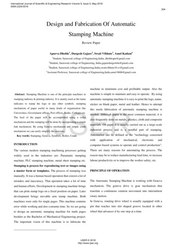
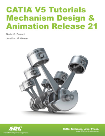
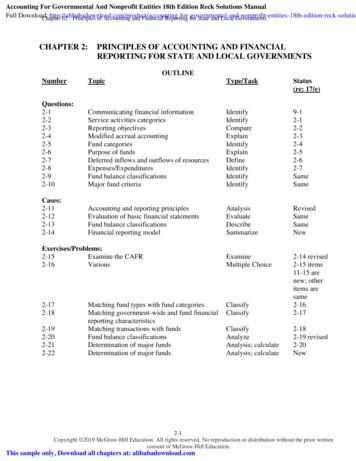
Study on the Mechanism of Nugget Growth Behavior in Three Sheets Stack Resistance Spot Welding(a)200 (b)200 100 200 Fig. 5 Comparison of nugget growth at 7.5 kA and 6 cyclewelding condition; a) Al-HPF combination b)TRIP combination200 100 Fig. 4 Coalescence of two nuggets in Al-HPF combination during early resistance spot welding timefor both combination, and nugget is formed between themiddle and bottom sheet. The nugget size is more extensive for the TRIP combination than the one of theAl-HPF combination. in this interface. However, a different phenomenon is observed in the case of Al-HPFcombination. At higher magnification, Al-HPF combination shows the presence of two nuggets (Fig. 4). Theother nugget form close to the geometric center of themiddle sheet of the Al-HPF combination. The solidification direction of both nuggets and equiaxed grain inthe merging point of two nuggets confirms the presenceof two nuggets. It is believed that the heat generated intwo interfaces of Al-HPF combination due to high contact resistance conducted to the geometric center of themiddle sheet. There is also the additional heat generation due to sheet own bulk resistance. The combinedeffect might initiate the melting in the geometric centreof the middle sheet of the Al-HPF combination. Theconcave heat flow pattern from both interfaces to themiddle sheet suggests the occurrence of heat conductionfrom both interfaces to the middle. It is mentioned thatmelting in middle sheet is highly dependent on the massof the middle sheet in three sheets spot welding. If themass of the middle sheet is not sufficient enough, melting will occur here as it cannot absorb all heat conducted from both interfaces6).The welds were made at 7.5 kA and 6 cycles to investigate the nugget growth direction, and its macro- structures are shown in Fig. 5. It can be seen that for Al-HPFcombination the nugget growth rate is higher electrodedirection (Fig. 5(a)). However, for the TRIP combination, the nugget growth rate is higher in sheet direction(Fig. 5(b)). As for Al-HPF combination nugget growthrate is higher in electrode direction, it should give largerpenetration and nugget diameter in thin sheet withwelding schedule of 7.5 kA and 21 cycles. However, theweld growth curve suggest TRIP combination having a대한용접․접합학회지 제37권 제6호, 2019년 12월higher button diameter than the Al-HPF combination.Therefore, the TRIP combination should have a largenugget diameter in a thin sheet because nugget diameteris proportional to button diameter. So there is a contrastin nugget formation mechanism and nugget diameter.More detailed observation of the penetration on a thinsheet, the microstructure of thin sheet interface for bothcombinations are shown in Fig. 6.The Al- HPF combination nugget having a penetrationof 179 µm in the thin sheet, which is higher than TRIPcombination (129 µm) based on optical microstructuralconfirmation of melting at the interface “A”. This couldbe a reasonable prediction by observing the nuggetgrowth mechanism of two combinations during first 6welding cycles. The Al-HPF combination shows lowernugget diameter (3.00 mm) than the TRIP combinationin thin sheet, which is different from predicted nuggetgrowth rate pattern.To investigate this phenomenon, the high speed camera incorporated into the captured images for gaininginformation on a heat generation pattern during thewelding. The video was synchronized and snapshot wascaptured in cycles. The results are shown in Fig. 7.From the images, it can be seen that for Al-HPF combiCombinationNugget diameterSGARC HPF DP590SGARC TRIP DP590Fig. 6 Penetration depth and nugget diameter comparison in full welding schedule; a) Al-HPF combination b) TRIP combination567
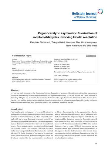
Nazmul Huda, Dae-Geun Nam and Yeong-Do ParkHPF combination7 Cy8 Cy4 Cy5 Cy9 Cy21 CyTRIP combination6 Cy21 CyHigh indentationFig. 7 Comparison of nugget formation mechanism with welding time for HPF combination and TRIP combination (Highspeed camera still image)568AI-HPFTRIP 780400Hardnessnation melting initiate at 7 cycles (Fig. 7). In the subsequent cycles the Al-HPF shows the nugget growth inelectrode direction and finally at 21 cycles shows goodpenetration in the thinner sheet. This is also observed inthe full experimental welding schedule (7.5 kA, 21 cycle). For TRIP combination the initial melting is muchearlier at 4cycles. In the subsequent cycle, it shows nugget growth sheet direction. At end of welding (21 cycle)though there is little penetration in thinner sheet it ishaving higher nugget diameter in thinner sheet compareto Al-HPF combination. This phenomenon is also observed in full experimental schedule.Another distinguishable phenomenon is observed inhigh-speed camera video and snapshots between thesetwo combinations. There is a gradual increase in indentation as the welding goes as nugget grows. The topelectrode pushes the top thin sheet into the molten metal, growing from interface “B” during this gradualindentation. The TRIP combination finally subjected tohigher indentation than the Al-HPF combination. To investigate the high indentation phenomena, the hardnessof both combination middle sheets is measured sincethe materials of middle sheet is the only difference between these two combinations. The middle sheet of theAl-HPF combination has almost two times of hardnessthan the one of the TRIP combination, as shown in Fig.8. However, it is difficult to conclude the effect of hardness on indentation at high temperature, which is closeto the melting temperature of the steel sheet. It is morereasonable that the higher heat generation at early welding time in the TRIP combination than the Al-HPFcombination contributes the more substantial amount ofplastic deformation for the indentation.Moreover in SORPAS simulation, it was found thetemperature profile of TRIP combination along inter-2000Material conditionFig. 8 Hardness comparison of middle sheet of HPFcombination and TRIP combinationface “A” and middle sheet center line is higher than theAl-HPF combination at a simulation schedule of 7.5kA, and 21 cycles (Fig. 9), which suggests heat generation is higher TRIP combination. This high heat generation might be due to the higher chemical composition of TRIP 780. Heat generation in sheets will be followed by a change in the properties of sheets. Consequently, the strength of the steel sheets decreases, andlarger indentation can occur, leading to an increase inthe contact area between electrode to top sheet and topsheet to the middle sheet. Besides, there is an increasein dynamic resistance due to an increase in bulk resistance as temperature rise7). This high temperature generates more melting in the fusion zone. Thereby nuggetvolume is a higher for the TRIP combination than AlHPF combination as shown in Fig. 10(a). Both this lowhardness as well as high nugget volume in TRIP combination cause a high indentation in the TRIP combination.It is reported that the mechanical properties, as well asnugget volume, has relevance to indentation. The inJournal of Welding and Joining, Vol. 37, No. 6, 2019
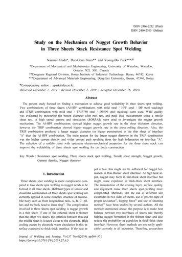
Study on the Mechanism of Nugget Growth Behavior in Three Sheets Stack Resistance Spot 100Center ofmiddle sheet1950At interface ATemperature (C)1950Temperature 02.03.04.05.06.07.00.08.01.0Distance from center(mm)2.03.04.05.06.07.08.0Distance from center(mm)Fig. 9 Temperature profile comparison along interface “A” and centre line of middle sheet at wdling current of 7.5 kA forHPF combination and TRIP .07Nodal displacement (mm)Nugget volume 403020(b)0.060.050.040.030.020.01107.5kA, 3.0kA0024681012141618200.0022240100Cycle800Current density (A/mm2)200300400Process time (ms)HPF combinationTRIP combination(c)6004002000100200300400Welding time (ms)Fig. 10 (a) Nugget volume, (b) electrode displacement, and (c) current density difference at interface “A” for HPF combination and TRIP combination based on SORPAS simulation schedule of 7.5 kA and 3.5 kNdentation increase with the increase of welding currentand indentation has the primary relevance to nuggetvolume8). The indentation difference also observed inFig. 10(b), which the data were given from SORPAS simulation. Here weld time is plotted as millisecondwhere 16.67 ms means 1 cycle. The electrode displacement is taken between two nodal points. The two nodalpoints are taken at top-electrode to top sheet contact대한용접․접합학회지 제37권 제6호, 2019년 12월point and bottom-electrode to bottom sheet contactpoint. It is also reported that the electrode to sheet andsheet to sheet deformation influences the weld currentdensity1). In SORPAS simulation the difference in current density is investigated in interface “A”. The TRIPcombination possesses a higher current density than theHPF combination, which is shown in Fig. 10(c).Moreover, high indentation can influence the contact569
Nazmul Huda, Dae-Geun Nam and Yeong-Do Park(a)(b)DHPFDTRIPFig. 11 Difference in current path width of (a) HPF combination and (b) TRIP combination during resistance spot weldingarea between electrode to the sheet. It is reported that asoft material will be indented by the electrode morethan a hard material. This high indent will cause an increase in the contact area between the sheet andelectrode. As TRIP combination middle sheet TRIP 780having low hardness as well as possesses higher nuggetvolume during welding, will be subjected to higher indentation than Al-HPF combination as Al-HPF combination middle sheet having high hardness and lowernugget volume during welding. So the current path widthwill be more extensive for the TRIP combination thanthe Al-HPF combination which will give higher nuggetdiameter in a thin sheet of trip combination though penetration can be less in a thin sheet. The mechanism canbe shown according to the following Fig. 11. Farson et.almonitored the nugget diameter with change of electrodedisplacement during the cooling stage of welding9) andfound indentation increases the nugget diameter. Nilsenet. al mentioned the observation of gaining higher nuggetdiameter in a thin sheet in three sheets spot welding duehigher indentation2). Jo et al. reported larger weldingcurrent process window for high electrode force compare to low electrode force in resistance spot welding10).So it can be concluded that though too much indentationis defined as a bad quality in resistance spot welding, itcan have significant effect to get good weldability inthree sheets spot welding.5. Conclusions1) Two different combinations (difference in the middle) of three sheets is used to find out the mechanism toget better nugget diameter in a thin sheet in three sheetsspot welding. The difference in electro- mechanicalproperties of the middle sheet provides a significant effect of forming nugget in a thin sheet in three sheetsspot welding.2) Due to higher contact resistance in the interfaces,the HPF combinations show higher heat generation ininterfaces than the trip combinations. For TRIP, combination melting was observed in interface “B”, but forHPF, combination melting was observed in interface570“B” as well as in the geometric center. The reason formelting in the geometric center might be due to thehigher heat conduction from both interfaces to the geometric center.3) The TRIP combinations show nugget growth ratehigher in sheet direction while the HPF shows in electrode direction. However at the end of welding, theTRIP combinations show better nugget diameter in thinsheet though it has lower penetration than the HPFcombination.4) The TRIP combination shows better nugget diameter in a thin sheet than HPF combination because ofhigher indentation resulting from low hardness and highnugget volume. Indentation can increase the nugget diameter by increasing the current density and currentpath width.5) The material with proper bulk resistance and hardness in a middle of three sheets spot welding can givebetter weldability.AcknowledgementThis work was supported by Dong-eui University Grant.(201902150001)ORCID: Nazmul Huda: https://orcid.org/0000-0001-5857-5278ORCID: Dae-Geun Nam: http://orcid.org/0000-0003-2360-722XORCID: Yeong-Do Park: http://orcid.org/0000-0002-0165-4749References1. J. Shen, Y. Zhang, X. Lai and P. C. Wang, Modeling ofResistance Spot Welding of Multiple Stacks of SteelSheets, Mater. Des, 32(2) (2011) 232. C. V. Nielsen, K. S. Friis, W. Zhang and N. Bay, ThreeSheet Spot Welding of Advanced High-strength Steels,Weld. J. 90(2S) (2011) 32s-40s.3. J. Gould, W. Peterson and J. Cruz, An Examination ofElectric Servo-guns for the Resistance Spot Welding ofComplex Stacks-ups, Weld. World, 57(2) (2013) . N. D. Uijl, Resistance Spot Wlding of Cmplicated Jointin New Advanced High Strength Steel, Proceeding 6thInt. Seminar on Advances in Resistance welding. Hamburg,(2010) 40-54.5. N. Huda and Y. D. Park, Weldability Evaluation andNugget Formation Mechanism in Three Sheets SpotWelding, Trends Weld. Res. (2012) 680-684.6. N. Harlin, T. B. Jones and J. D. Parker, Weld GrowthMechanisms During Resistance Spot Welding of Twoand Three Thickness Lap Joints, Sci. Technol. Weld. Join.7(1) (2002) urnal of Welding and Joining, Vol. 37, No. 6, 2019
Study on the Mechanism of Nugget Growth Behavior in Three Sheets Stack Resistance Spot Welding7. J. Senkara, H. Zhang and S. J. HU, Expulsion Predictionin Resistance Spot Welding, Weld. J. 83(4) (2004) 123-S.8. F. Hayat, The Effect of the Welding Current on Heat inPut, Nugget Geometry and the Mechanical an FracturalProperties of Resistance Spot Welding on Mg/Al Dissimilar Materials, Mater. Des. 32(4) (2011) 015대한용접․접합학회지 제37권 제6호, 2019년 12월9. D. F. Farson, J. Z. Chen, K. Ely and T. French, Monitoring Resistance Spot Nugget Size by Electrode Displacement, J. Manuf. Sci. Eng. 126(2) (2004) 391-394.10. H. Jo, Y. Kim, M. Kang and D. Kim, Effects of ElectrodeFace Radius and Force on Resistance Spot Weldabilityof Aluminium Alloy 6061, J. Weld. Join. 36(6) 8571
of the welded parts were revealed by using picral etch-ant (1% HCl, 3% picral and 96% ethanol). For high speed camera video, the experimental schedule used is 1.75 kN electrode force, welding current 3.0 kA and weld time 21 cycles with half-cut electrode on both sides.