Transcription
VPG TRANSDUCERSLoad Cells and Weigh ModulesTechnical Note VPGT-02Load Cell Accuracy in Relation to theConditions of Use1. Load Cell Accuracy1.2 Europe/WorldwideLoad cells are ranked, according to their overallperformance capabilities, into differing accuracyclasses or grades. A specific accuracy grade specifiesan error envelope for certain parameters, such aslinearity, hysteresis, temperature effects, creep, etc.In Europe, guidelines for legal for trade weighingsystems have been treated differently in differentcountries. In order to harmonize and standardizeon an international basis, a convention was heldin Paris on October 12, 1955, and the participatingStates (countries) agreed to set up an InternationalOrganization of Legal Metrology.In practice, certain system accuracy parametersdepend considerably on the application of use,physical load introduction to the transducer anddisturbing factors such as Zener barriers and surgeprotection devices.This technical paper will cover load cell accuracygrades according to the OIML and NTEP standards,and their compatibility when used in legal for tradeweighing instruments. It will also cover key terminologyand metrological terms which are used by load celland scale manufacturers, as well as Weights andMeasures Authorities.In addition to this, the article will focus on thoseconditions of load cell use that either compromise, orenhance the actual scale performance.1.1 United StatesIn the United States, guidelines for legal for tradeweighing instruments are laid down in handbook 44of the National Institute of Standards and Technology(NIST). The evaluation of critical metrology equipmentand components, including load cells, is formalized bythe National Type Evaluation Program (NTEP).NTEP Class III covers most commercial weighingapplications for systems which have between 500and 10,000 scale divisions. Class IIIL specifically coverslarger capacity applications such as vehicle, axleload, livestock, crane and railway track scales as wellas hopper scales (other than grain hopper) whichhave between 2000 and 10,000 divisions. Each ofthese classes can be further subdivided into Singleand Multiple, depending on whether one or moreload cells are used in a particular system.The load cell error tolerance for Single is set at 0.7 timesthe scale divisions, while Multiple is set at 1.0 times thescale divisions.Document Number: 11864Revision: 08-Jan-2015Because the official language was French, the nameof the organization is Organization Internationale deMetrologie Legale.OIML Recommendations and Documents relateto specific measuring instruments and technology.International Recommendations (OIML R) are modelregulations generally establishing the metrologicalcharacteristics required of the measuring instrumentsconcerned and specifying methods and equipmentfor checking their conformity. OIML member states areexpected to implement these Recommendations asfar as possible.OIML class III covers the commercial weighingapplications between 500 and 10,000 divisions. TheOIML does not recognize the difference betweenSingle and Multiple cell applications, but it acceptsand utilizes the concept in the apportionment oferrors (OIML R76). Load cells are tested and certifiedaccording to OIML R60. The load cell error tolerance isset at 0.7 times the scale division.VPG Transducers manufactures products meetingNTEP, OIML and in-house specifications. Dependingupon the standard and the per formance of aparticular load cell type, an alphanumeric “accuracygrade” is given to the product. The alpha designaterefers to the specific accuracy class, while the numericpart refers to the number of divisions:Az Products meet the NTEP requirements for class IIIapplications.Bz Products meet the NTEP requirements for class IIILapplications.Cz Products meet the OIML requirements for class IIIand IIII applications.Note: “z” represents the number of divisions (x1000), i.e., A3, B10,C6, etc.Technical contact: com, and vpgt.emea@vpgsensors.comwww.vpgtransducers.com1
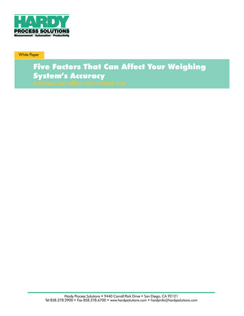
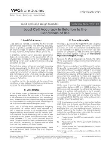
Technical Note VPGT-02Load Cell Accuracy in Relation to the Conditions of Use1.3 Accuracy Related TermsAccuracy class:A class of load cells which are subjected to the sameconditions of accuracy. A load cell is classified by thealphabetical classification and the maximum numberof load cell intervals stated in units of 1000.Load cell verification interval:The load cell interval (v), expressed in units of mass, usedin the test of the load cell for accuracy classification.Number of verification intervals:The number of verification intervals (n), used in the testof the load cell for accuracy classification.Creep:The change in load cell output occurring with timewhile under constant load ( 90% of the load cellcapacity) and with all environmental conditions andother variables remaining constant.OIML recommendation R76 requires a 30 minute testand specifies an error limit for this time period, as wellas the last 10 minutes (20 to 30 minutes). NTEP requires aone hour test and specifies an error limit for this period.Minimum Dead Load Output Return (MDLOR):The difference in load cell output at minimum deadload, measured before and after a 30 minute loadapplication of at least 90% of the cell's rated capacity(OIML only).Non-linearity:1)a straight line which passes through minimumload output and the load cell output at75% of the measuring range (OIML load cellverification).2) a straight line connecting the zero load andthe rated load output values (scales).3) the best straight line fitted to output values bythe least squares method, through zero loadoutput.All measurements at a stable ambient temperature of20 C or 68 F.Hysteresis:The difference between load cell output readingsfor the same applied load, one reading obtained byincreasing the load from minimum load and the otherby decreasing the load from maximum load.1VLOutputThe deviation of the increasing load cell calibrationcurve from either:V02TimeFigure 2. Creep (1) and MDLOR (2)Temperature effect on minimum dead loadoutput:The change in minimum dead load output due to achange in ambient temperature.Temperature effect on sensitivity:The change in sensitivity due to a change in ambienttemperature.OutputOutput2211LoadLoadFigure 1. Non-linearity (1) and Hysteresis (2)www.vpgtransducers.com2Figure 3. Temperature effect on minimumdead load output (1) and sensitivity (2).Technical contact: com, and vpgt.emea@vpgsensors.comDocument Number: 11864Revision: 08-Jan-2015
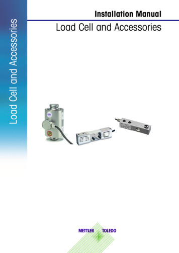
Technical Note VPGT-02Load Cell Accuracy in Relation to the Conditions of Use1.4 Load Related TermsCombined error:The total error envelope allowed for a load cell as thelimiting factor. The approach taken by NTEP and OIMLrecognizes that several errors must be consideredtogether when fitting performance characteristics tothe error envelope permitted.It is not considered appropriate to specify individualerror limits for given characteristics (non-linearity,hysteresis and temperature effect on sensitivity).The use of an error envelope or combined errorconcept allows balancing individual factors to thetotal error of measurement while still achieving theintended results.Minimum verification interval (vmin ):Most weighing systems use load cells where theirworking or measuring range is well below their ratedcapacity. In these situations, the values for the loadcell utilization and minimum verification interval (vmin )are important.The minimum verification interval is defined as thesmallest value of a quantity (mass) which maybe applied to a load cell without exceeding themaximum permissible error. It is specified as E max γ,where E max represents the load cell's rated capacityand γ represents a value which is specified by the loadcell supplier.Minimum dead load (E min):The smallest value of a quantity (mass) which maybe applied to a load cell without exceeding themaximum permissible error.Maximum capacity (E max):The largest value of a quantity (mass) which maybe applied to a load cell without exceeding themaximum permissible error.Load cell measuring range:The range of values of the measured quantity for whichthe result of measurement should not be affected byan error exceeding the maximum permissible error.Safe load limit:The maximum load that can be applied withoutproducing a permanent shift in the performancecharacteristics beyond those specified.Ultimate load limit:The maximum load that can be applied withoutphysical destruction of the load cell. Specified as apercentage of E max.No load EminThe minimum verification interval is inextricably linkedto the utilization of the load cell. The utilization can bedefined as the minimum measuring range (MMR) for aparticular load cell over which full specification will bemaintained. The following formulas can be applied:orDminMMR(kg/lbs) vmin * nmaxor1000 * 3000 10000 300 kg3000 * 100 10000 30%The minimum measuring range can apply overany part of the measuring range between zeroload and the load cell's rated capacity. The abovecalculation applies to a single cell application.Document Number: 11864Revision: 08-Jan-2015Emax Safe load Ultimate loadMeasuring rangeDmaxFigure 4. Load related terms. The terms above thecentral horizontal line are fixed by the design of theload cell, while the terms below are fixed on theconditions of use and cell performanceMMR(%) nmax * 100 γFor example an SSB-1t-C3 load cell, withvmin E max 10000 has a minimum measuring range ofMaximum Measuring range1.5 Single Internal SystemsLegal for trade single inter val weighing systemsrequire load cells which are certified according tothe National Type Evaluation Program (NTEP) or OIMLrecommendation R60 (Europe). The requirements interms of load cell accuracy for the above mentionedsystems are:1)Select a cell which is certified accordingto the appropriate standard, i.e., productsdesignated “Cz” for class III applications.Technical contact: com, and vpgt.emea@vpgsensors.comwww.vpgtransducers.com3
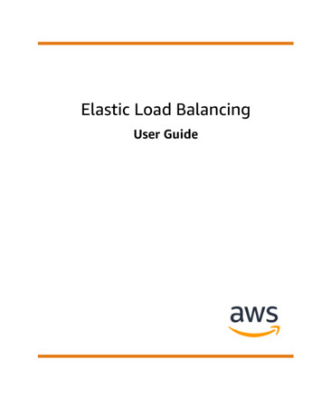
Technical Note VPGT-02Load Cell Accuracy in Relation to the Conditions of Use2) For each load cell, the maximum number ofload cell intervals shall not be less than thenumber of verification scale intervals. Forexample, a 3000 division class III scale requiresC3 load cells.3) The minimum load cell verification interval shallsatisfy the condition:vmin e * R Nwhere e represents the scale verification intervaland R represents the reduction ratio of the loadtransmitting device (hybrid scales).R Load acting on the load cells Load actingFor example:A fully electronic scale (R 1), with four load cellsand a measuring range of 1500 kg divided into 3000divisions requires load cells with the following vmin:vmin (1500 3000) * (1 4), i.e., vmin 0.25 kg1.6 Maximum Permissible ErrorsTable 1 represents the combined error envelope forload cells and systems while table 2 represents theload cell requirements for the other performancecharacteristics: repeatability, creep, MDLOR andtemperature effect on minimum dead load output.The differences between A, B, and C class loadcells becomes apparent when the combined errorenvelopes or tolerance bands are compared.However, to get a clear comparison it is importantto compare them in absolute terms, rather than interms of load cell divisions. Figure 5 represents theerror envelope graphs for a sample load cell with acapacity of 30,000 weight units (lbs/kg).NTEP Class III Single falls in line with OIML; however anadditional tolerance step at 4000d is permissible for A5compared to C5.Note: The output per scale division (μV d) needs to be verifiedto ensure compatibility with the indicator.2015A5 SingleC5A5 MultipleB6 Single105051015202530-5-10-15-20Full scale output in units of mass (x1000)Figure 5. Combined error comparisonwww.vpgtransducers.com4Technical contact: com, and vpgt.emea@vpgsensors.comDocument Number: 11864Revision: 08-Jan-2015
Technical Note VPGT-02Load Cell Accuracy in Relation to the Conditions of UseTable 1: Combined error envelope for load cells and systemsClassIIIIIILDivisionsWeighingMachine NISTH44WeighingMachine OIMLR76Load CellNIST H44SingleLoad CellNIST H44MultipleLoad CellOIML R600 – 5000.5d0.5d0.35v0.5v0.35v501 – 20001.0d1.0d0.7v1.0v0.7v2001 – 40001.5d1.05v1.5v4001 – 100002.5d1.75v2.5v0 – 5000.5d0.35v0.5v501 – 10000 0.5d 500d 0.35v/500d 0.5v 500d1.5dN/A1.05vN/ATable 2: Repeatatability, creep, MDLOR and temperature effect on MDLONTEP CLASS IIILVerificationIntervals (Load)NTEP CLASS IIILVerificationIntervals (Load)Single0 – 500v0.70v1.00v0 – 500v0.70v1.00v0.35v501 – 1000v1.40v2.00v501– tiple 500v 0.70v 1.0v2001 – 4000v2.10v3.00v9501 – 10000v14.0v20.0v4001 – 10000v3.50v5.00vCreep (*)OIML Class C1.05v0 – 500v0.25v0.25v0 – 500v0.50v0.50v0.245v501 – 1000v0.50v0.50v501– 2000v1.00v1.00v0.490v 0.25v 0.25v5.00v5.00v 500v9501 – 10000v2001 – 4000v1.50v1.50v0.735v4001 – 10000v2.50v2.50v0.50v0 – 500vMinimum dead loadoutput return(OIML R60 only)Temperature effecton minimum deadload outputN/A501– 2000v2001 – 10000v2.1 vmin 5ºCN/A0.50v0.7 vmin 5ºC(*) NTEP Class IIIL and III; test at 90–100% of rated capacity for one hour. OIML R60 Class C; test at 90–100% of rated capacity for halfan hour, 0.15 * maximum permissible error between 20 and 30 minutes.2. Conditions of UseLoad cells are ranked into differing accuracy classesbased on their performance in pre-described tests,with specified equipment. In almost all cases testsare performed with optimal load introduction to thetransducer, at stable ambient temperatures.But actual load cell performance in any weighinginstrument depends considerably on the conditionsDocument Number: 11864Revision: 08-Jan-2015of use. Disturbing factors may include load cellutilization, temperature gradients, eccentric loadintroduction, torque on fixing bolts for beams, Zenerbarriers, surge protection devices, stiffness of thesupport structure, etc.2.1 Load Cell UtilizationThe load cell measuring range (MR) is defined asthat range in which the result of measurement isTechnical contact: com, and vpgt.emea@vpgsensors.comwww.vpgtransducers.com5
Technical Note VPGT-02Load Cell Accuracy in Relation to the Conditions of Usenot affected by an error exceeding the maximumpermissible er ror. The following expression canbe used:MR E max – E min n*vwhere, “n” represents the number of verificationintervals and “v” represents the load cell verificationinterval, expressed in units of mass.Most weighing systems use load cells where theirmeasuring range is well below their rated capacity.The minimum measuring range can be calculated by:MMR vmin * nwhere, v min represents the minimum verificationinterval, specified by the load cell supplier. Theminimum measuring range can apply over any partof the measuring range between zero load and theload cell's rated capacity.The maximum load on the transducer (D max) can becalculated by:D max (vmin * n) D minwhere, D min represents the contribution of the systemdead load.2.1.1 Linearity and HysteresisIn general, linearity and hysteresis will improvewhen a smaller part of the measuring range is used.The improvement depends primarily on the initialperformance for both characteristics and on theactual measuring range of the transducer (va * n).3421Figure 6. Performance of a sample loadcell at varying utilization levelsFigure 6 represents the combined error performanceof a sample load cell with a rated capacity of 500 kg.The cell has been measured with a utilization of 20%(1), 40% (2), 60% (3) and 80% (4) of the rated capacity.www.vpgtransducers.com6By reducing from 80 to 20% utilization, the non-linearityhas improved by a factor of 7, while the hysteresis hasimproved by a factor of 8!2.1.2 Creep and MDLORThe effect of utilization on creep will depend on whichpart of the measuring range is being used for thescale; creep will be more significant in a scale whereits working range is at the top end of the load cell'srated capacity than when it is at the bottom.Extensive tests have shown that the following formulacan be used to predict approximate load cellperformance:y (D max E max) * xwhere, “x” represents the performance on creepor MDLOR measured over the load cell's fullmeasuring range, and “y” represents the improvedperformance when the load does not exceed D max.It is important to recognize that the system deadload contributes directly to the maximum load onthe transducer (D max) and as such influences theperformance improvement which may be achieved.This is not applicable for improvements which may beachieved on linearity and hysteresis.2.1.3 Restrictions / ConsiderationsThe temperature effect on zero load output or sensitivityis a fixed error percentage of the load cell output at acertain utilization. These characteristics will thereforenot improve when load cells are used over a partof their measuring range. The minimum verificationinterval is directly related to the temperature effect atzero load.In general, the overall accuracy of a weighing systemwill improve when load cells are used over a (smaller)part of their measuring range. In addition to this thesystem will be stronger in terms of load cell overloadrisk.The output per scale division should be verifiedagainst the required minimum signal level for themeasuring device or indicator. Smaller signals arealso more susceptible to noise (electromagneticinterference) or temperature effects on extensioncables and additional hardware (balancing resistors,barriers, etc.).Technical contact: com, and vpgt.emea@vpgsensors.comDocument Number: 11864Revision: 08-Jan-2015
Technical Note VPGT-02Load Cell Accuracy in Relation to the Conditions of Use2.2 Load IntroductionLoad cells are tested and ranked while beingloaded under optimum conditions. Normally it willbe extremely difficult (if not impossible) to reproducethese conditions when load cells are used in practicalapplications. As a result the initial load cell accuracyand repeatability may be compromised to suchan extent where scale performance is no longeracceptable.Load cell performance may be compromised bylateral forces, bending moments, torsion moments oroff center loading. The following terms are used todescribe loading conditions:Principal axisThe axis along which the load cell is designed to beloaded.Axial loadLoad applied along the principal axis of the load cell(correct loading).Side loadA load acting at a 90 degree angle to the principalaxis of the load cell on the specified loading surfaceand in a defined direction.2.2.1 Concentric LoadingThe effect of concentric loading can be determinedby the use of wedge shaped pads above and belowthe load cell. Eight measurements at intervals of 45 should be taken to find the maximum error whichshould be specified. The error value at each positioncan be calculated by:e1 [(Sr – Se cos ) Sr] * 100%where, S e represents the average rated outputand Sa represents the average rated output underconcentric loading conditions.The formula above compensates for the fact that theapplied force L a under angle a will have a verticalcomponent Lp. Lp can be calculated by:Lp cos * L aEccentric loadA load applied parallel to the principal axis at aspecified location and eccentricity.LsInclined load, concentricA load applied through the principal axis of the loadcell at the point of load application, inclined at anangle and at a defined direction with respect to theprincipal axis.Inclined load, eccentricA load applied eccentric to the principal axis of theload cell at the point of load application, inclined atan angle and at a defined direction with respect tothe principal axis.ßLoad Axis 2Concentric inclinedloading 1aLoad Axis 3Eccentric inclinedloading(1) Load Axis 1Eccentric loadingPrincipal AxisFigure 7. Eccentric and angular loadingDocument Number: 11864Revision: 08-Jan-2015LaLoading AxisLpLaLpPrincipal axisFigure 8. Concentric loadingInclined loading effects should be considered forcompression type cells only. Because of bendingeffects in the column, single column load cells aremore sensitive than multiple column cells.The effect on beam type load cells is usually very smalland can be partly compensated for in the calibrationof the weighing instrument.2.2.2 Eccentric LoadingThe effect of eccentric loading can be determinedby applying a load, displaced at a distance “a” fromthe principal axis. Eight measurements at intervals of45 should be taken to find the maximum error whichshould be specified.Technical contact: com, and vpgt.emea@vpgsensors.comwww.vpgtransducers.com7
Technical Note VPGT-02Load Cell Accuracy in Relation to the Conditions of UseThe error, as a percentage of the rated output, at eachangular position can be calculated by:e1 (Sr – Se Sr) * 100%where, Se represents the average rated output whilethe cell is being loaded eccentrically.Enhanced scale performance is offered when loadcell orientation in a system is based on a modelspecific eccentric loading diagram (Figure 9). Thisdiagram represents the typical error experiencedwhen a load cell is eccentrically loaded in a defineddirection.21connecting the four strain gages (or a multiple of four)in a Wheatstone bridge configuration. The raw outputof the Wheatstone bridge needs further compensationin order to offer a calibrated, temperature stablesignal.Sensing elements can be made of tool steel (nickelplated for protection against corrosion), stainlesssteel, aluminium or a copper-beryllium alloy. All thesematerials respond to temperature changes with anon-linear length increase (the elasticity modulus ofsteel varies with temperature).In general, two mechanisms are used to compensatefor the above mentioned temperature effects. Firstly,a temperature dependant wire is connected into theWheatstone bridge to compensate the offset for nonhomogeneous changes in component resistance andsteel elasticity. Secondly, so called modulus resistorsare connected in the excitation lines to compensatethe span for a varying elasticity modulus at varyingtemperatures. Modulus resistors are usually made likea strain gage and are also glued to the element inorder respond rapidly to any change of temperature.2Figure 9. Specific eccentric loading diagramof a bending beam (1) and shear beam (2) typeload cell, showing the error experienced atdefined eccentric angular positionsA typical eccentric loading diagram can only beprovided when load cells are produced with highlyconsistent manufacturing processes.2.2.3 SummaryLoad cell performance may be compromised bya variety of disturbing factors such as concentricangular loading, eccentric loading, side loading, etc.Loading effects can be reduced not only with suitableload introduction devices or mounts but also withoptimum scale design, based on information providedby the load cell manufacturer.2.3 Temperature GradientsThe measuring principle of any strain gage load cellis based on a spring or so called sensing elementwhich deflects repeatable when loaded. Strain gagesare used to identify strain in the element in terms ofa resistance change. This change in resistance canthen be converted into a usable electrical signal bywww.vpgtransducers.com81Figure 10. Offset (1) and span (2) temperaturecompensation. The modulus resistors have afixed resistance value for a certain load cell modeland are being shunted with a so called modulusparallel resistor to obtain specific valuesThe temperature compensation system of load cellsprovides consistent output readings when the load cellis stabilized at varying temperatures.Dynamic temperature changes may induce errorswhich far exceed the allowed limits. The magnitude ofthese errors depends not only on the load cell designitself and on the location of the strain gages andmodulus resistors, but also on the element size andmeasuring principle.Technical contact: com, and vpgt.emea@vpgsensors.comDocument Number: 11864Revision: 08-Jan-2015
Technical Note VPGT-02Load Cell Accuracy in Relation to the Conditions of UseCanister load cells are far more susceptible to dynamictemperature changes than beam load cells. Whenused in outdoor applications, appropriate screensagainst direct sunlight should be used at all times.Temperature gradients may also be caused in processapplications where load cells support heated vesselsor containers. Insulation pads between load cells andthe vessel should be used to minimize errors. In additionto this load cells with a relatively fast temperaturesettling time should be selected. Temperature settlingtimes generally vary from 1 hour per 10 C/18 F for smallcompact beams to 5 hours per 10 C/18 F or more forcanisters. Load cell suppliers should be encouraged tospecify this important characteristic.2.4 Load Cell DeflectionFp Fs * d lwhere, Fp represents the vertical component alongthe principal axis of the load cell, Fs represents theside force and d represents the load cell deflection.The formula shows that errors can be reduced byselecting the length of the stay rod to be as longas possible, or by selecting load cells with a lowdeflection.The horizontal force Fs on the stay rod may vary at anytime, causing an undefined span error which can notbe compensated for at system calibration!2.5 Zener Barriers and SPDsLoad cells are often considered as a solid piece of steelon which platforms, vessels, etc., can be supported.The performance of a load cell depends primarily onits ability to deflect under highly repeatable conditionswhen load is applied or removed. From an accuracypoint of view, a weighing system should be free fromits surroundings. However, in most process applicationsa contact between the weighing system and itssurroundings is present. Examples are: pneumatic/hydraulic hoses, electrical cables, pipes, bellows andconstrainers. If the influence of external connectionsto the weighing instrument is not constant, nonrepeatability, hysteresis and span errors will beintroduced.Perhaps the most common and easiest to understandsystem is a vessel restrained by stay rods.ldFsFpFigure 11. Forces acting on a stay rodStay rods are used if major load movement isanticipated, for example in weighbridges or vesselswith an agitator. Stay rods are installed horizontallyand should not transfer any forces to the vessel orplatform. However, because of the inherent loadcell deflection, errors are unavoidable. The followingDocument Number: 11864Revision: 08-Jan-2015expression could be used to calculate the verticalcomponent of a side force:Zener barriers are frequently used in systems whichare installed in hazardous areas. The barrier acts asa safety device which limits the energy that maybe transferred to the hazardous area under faultconditions.Surge protection devices or SPDs are used to protectsensitive load cell systems from damage caused by avariety of surges. For example, heavy power switching,lightning strikes, etc.Introducing barriers into a weighing system results inalmost all cases in temperature errors on offset andspan. The errors are caused by a change in end-toend resistance of the barrier, or by a change in theleakage current through the Zener diodes to ground.There are three basic options to avoid errors causedby barriers. The first option is to keep the barriers ata constant temperature. This is, for example, possibleif they are installed in an air-conditioned processcontrol room. The second option is the use of senselines in a balanced bridge circuit.Sense lines control the operating voltage at the loadcell(s) by either raising or dropping the excitationvoltage, or by changing the amplifier rate of theindicator.The third option is the use of temperature compensatedand Weights and Measures approved barriers.3. SummaryLoad cells are offered in a wide variety of accuracygrades or classes. The performance of Weights andMeasures approved load cells is traceable to OIMLTechnical contact: com, and vpgt.emea@vpgsensors.comwww.vpgtransducers.com9
Technical Note VPGT-02Load Cell Accuracy in Relation to the Conditions of Useor NTEP standards. These standards are commonlyused to compare and select load cells suitable for aparticular application.However, when used in practical applications, loadcell performance also depends considerably oninherent design features such as sensitivity to loadingconditions, dynamic temperature behavior, deflection,etc. Load cell manufacturers should be invited towww.vpgtransducers.com10provide information relating to such features whichcan assist installers optimize application performance.By thus extending the relationship between load cellmanufacturer and system designer, scale accuracycan be satisfied or enhanced. Alternatively, load celldedicated scale design should allow total costs to beminimized.Technical contact: com, and vpgt.emea@vpgsensors.comDocument Number: 11864Revision: 08-Jan-2015
2) a straight line connecting the zero load and the rated load output values (scales). 3) the best straight line fitted to output values by the least squares method, through zero load output. All measurements at a stable ambient temperature of 20 C or 68 F. Hysteresis: The difference between load cell output readings