Transcription
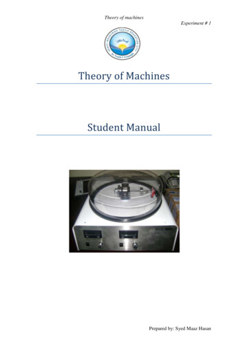
Theory of machinesExperiment # 1Theory of MachinesStudent ManualPrepared by: Syed Maaz Hasan
Theory of machinesExperiment # 1Experiment # 1To study the characteristics of four bar mechanism by applyingGruebler and Greshof conditions.Theory:Mechanism:A Mechanism is a device which transforms some input motion to somedesirable pattern of output motion. Following are some examples of mechanisms:Fig 1.1: A simple slider-crank mechanismFig 1.2: Four bar Mechanism [11]Mechanisms can be treated kinematically (without regard to the forces) if theyare lightly loaded or are run at very low speeds.Degree of Freedom:Number of inputs which need to be provided to in order to create a predictableoutput is called degree of freedom.ORIn case of mechanisms: Number of independent variables required tocompletely define all the positions in a mechanism is its degree of freedom.Gruebler Condition:The degree of freedom of any mechanism can be predicted using the Grueblercondition which is given by the formula:M 3L-2J-3GWhere:M degree of freedom or mobilityL number of linksJ number of jointsG number of grounded linksPrepared by: Syed Maaz Hasan
Theory of machinesExperiment # 1Note that in any real mechanism, even if more than one link of the kinematicchain is grounded, the net effect will be to create one larger, higher-order ground link,as there can be only one ground plane. Thus G is always one, and Gruebler's equationbecomes:M 3(L - 1) - 2JGrashof Condition:The Grashof condition is a very simple relationship which predicts the rotationbehavior or rotatability of a four bar linkage's inversions based only on the linklengths.Let:S length of shortest linkL length of longest linkP length of one remaining linkQ length of other remaining linkThen if:S L P QThe linkage is Grashof and at least one link will be capable of making a fullrevolution with respect to the ground plane. This is called a Class 1 kinematic chain. Ifthe inequality is not true, then the linkage is non-Grashof and no link will be capable ofa complete revolution relative to any other link. This is a Class II kinematic chain.The motions possible from a four bar linkage will depend on both the Grashofcondition and the inversion chosen. The inversions will be defined with respect to theshortest link. The motions are:For the Class I case,S L P QGround either link adjacent to the shortest and you get a crank-rocker, in whichthe shortest link will fully rotate and the other link pivoted to ground will oscillate.Ground the shortest link and you will get a double-crank, in which both links pivoted toground make complete revolutions as does the coupler. Ground the link opposite theshortest and you will get a Grashof double-rocker, in which both links pivoted toground oscillate and only the coupler makes a full revolution.For the Class II case,S L P QAll inversions will be triple-rockers in which no link can fully rotate.For the Class III case,S L P QReferred to as special-case Grashof and also as a Class III kinematic chain, allinversions will be either double-cranks or crank-rockers but will have "change points"twice per revolution of the input crank when the links all become collinear. At thesechange points the output behavior will become indeterminate. [1]Prepared by: Syed Maaz Hasan
Theory of machinesExperiment # 1Apparatus: Four Bar Mechanism Tri Square/Foot Scale StopperFig 1.3: Four bar Mechanism available in labProcedure: Count the number of links in a four bar mechanism. Count the number of joints in the mechanism. Using the Gruebler's equation: M 3(L - 1) - 2J calculate the degree offreedom of the four bar mechanism. Now, with the help of tri square/foot scale, measure the distance between eachhole in the mechanism and the corresponding link lengths which can beobtained in the given four bar mechanism. After each possible link length has been calculated, create all the possible linklength combinations by varying the link lengths using the stopper for the class Icase:S L P Q Similarly for the class II case, create all the possible link lengths which satisfythe equation:S L P Q Finally for the class III case, try to create all the possible link combinations byvarying the link lengths which satisfy the equation:S L P QPrepared by: Syed Maaz Hasan
Theory of machinesExperiment # 1 If any one of the cases cannot be satisfied for the given four bar mechanism,then mention the difficulty and discuss the solution for this problem.Calculations:Number of links:Number of joints:Gruebler's equation:Degree of Freedom:Tables:For Class I case:Sr.Link 1NoLength(Crank)Link 2Length(Coupler)Link 3Length(Rocker)Link n(degrees)For Class II case:Sr.Link 1Link 2NoLengthLength(Crank)(Coupler)Link 3Length(Rocker)Link n(degrees)For Class III case:Sr.Link 1Link 2NoLengthLength(Crank)(Coupler)Link 3Length(Rocker)Link n(degrees)Prepared by: Syed Maaz Hasan
Theory of machinesExperiment # 1Discussion:Prepared by: Syed Maaz Hasan
Theory of machinesExperiment # 2Experiment # 2To apply Grashof condition on a slider-crank mechanism and tostudy the variation in velocity and acceleration of the slider when thecrank is rotated with a constant angular velocity.Theory:Slider-Crank Mechanism:The slider-crank mechanism is a simple four bar mechanism in which the rockeris replaced by a slider. Thus the four links in the slider-crank mechanism are: Crank,Coupler/Connecting Rod, Slider and the Ground link. A simple slider-crank mechanismis shown below:Fig 2.1 Slider-crank Mechanism [11]The Slider-Crank mechanism can be used whenever there is a need ofconverting rotational motion to translational motion. The common applications ofslider-crank mechanism are the internal combustion engines, Bull Gear, locomotives,etc.Apparatus: Slider-crank Mechanism Tri Square/Foot Scale Stopper ScrewPrepared by: Syed Maaz Hasan
Theory of machinesExperiment # 2Procedure: Count the number of links in the slider-crank mechanism. Count the number of joints in the mechanism. Using the Gruebler's equation: M 3(L - 1) - 2J calculate the degree offreedom of the slider-crank mechanism. Now, with the help of tri square/foot scale, measure the distance between theeach of the three holes present in the crank of the slider-crank mechanism.These three holes represent the points where the stopper screw can be adjustedto vary the link length of the crank. Now, starting with zero, with the help of the angular scale available on thecrank, position the crank with an increment of every fifteen degrees and observethe corresponding position of the slider. Note down these values in the tableavailable. Do this procedure for the whole 360 degrees. Assuming an angular velocity of fifteen degrees per second, calculate thevelocities at each of the positions of fifteen degrees with the help of theformula:(P2- P1)/ (T2 –T1) whereP2 Final position of the slider.P1 Initial Position of the slider.T2 –T1 1 second After calculating the velocities of the slider at different points, calculate theacceleration at the same points with the help of the formula: (V2- V1)/ (T2 –T1)whereV2 Final velocity of the slider.V1 Initial velocity of the slider.T2 –T1 1 second Finally draw graphs of position, velocity and acceleration of the slider withrespect to the position of the crank. Apply the same procedure for the other two slider lengths.Prepared by: Syed Maaz Hasan
Theory of machinesExperiment # 2Table:Sr.No.CrankSliderSliderSliderTheoretical resultsAnglePosition Velocity AccelerationVel.Acc.(Degrees)(mm)(mm/sec) (mm/sec2) 15012.16513.18014.19515.210Prepared by: Syed Maaz Hasan
Theory of machinesExperiment # 2Sr.No.CrankSliderSliderSliderTheoretical resultsAnglePosition Velocity AccelerationVel.Acc.(Degrees)(mm)(mm/sec) (mm/sec2) 3024.345Calculations:Number of links:Number of joints:Gruebler's equation:Degree of Freedom:Prepared by: Syed Maaz Hasan
Theory of machinesExperiment # 3Experiment # 3To study the variation in velocity and acceleration of the sliderwhen the crank is rotated with a constant angular velocity in a slottedlink slider-crank mechanism.Theory:Slotted Link Slider-Crank Mechanism:The slotted link slider-crank mechanism is a simple variation of the normalslider-crank with the connecting rod replaced by a slotted link. Thus the four links inthe slotted link slider-crank mechanism are: Crank, Slotted Link Coupler/ConnectingRod, Slider and the Ground link. A slotted link slider-crank mechanism is shownbelow:Fig 3.1 Slotted Link Slider-crank Mechanisms[11]Apparatus: Slotted Link Slider-crank Mechanism Tri Square/Foot ScaleProcedure: Starting with zero, with the help of the angular scale available on the crank,position the crank with an increment of every fifteen degrees and observe thecorresponding position of the slider. Note down these values in the tableavailable. Do this procedure for the whole 360 degrees.Prepared by: Syed Maaz Hasan
Theory of machinesExperiment # 3 Assuming an angular velocity of fifteen degrees per second, calculate thevelocities at each of the positions of fifteen degrees with the help of theformula: (P2- P1)/ (T2 –T1) whereP2 Final position of the slider.P1 Initial Position of the slider.T2 –T1 1 second After calculating the velocities of the slider at different points, calculate theacceleration at the same points with the help of the formula: (V2- V1)/ (T2 –T1)whereV2 Final velocity of the slider.V1 Initial velocity of the slider.T2 –T1 1 second Then draw graphs of position, velocity and acceleration of the slider withrespect to the position of the crank. Now compare the results obtained for the slotted link slider-crank mechanismwith those obtained in the previous experiment of simple slider-crankmechanism and give some observations regarding the results.Graph:The graph obtained for the velocity of the slider with respect to the crankshould look like the following:V ofslider090180Angular position of CrankPrepared by: Syed Maaz Hasan
Theory of machinesExperiment # 3Table:Sr.No.CrankSliderSliderSliderTheoretical resultsAnglePosition Velocity AccelerationVel.Acc.(Degrees)(mm)(mm/sec) (mm/sec2) 15012.16513.18014.19515.210Prepared by: Syed Maaz Hasan
Theory of machinesExperiment # 3Sr.No.CrankSliderSliderSliderTheoretical resultsAnglePosition Velocity AccelerationVel.Acc.(Degrees)(mm)(mm/sec) (mm/sec2) 3024.345Observations:Prepared by: Syed Maaz Hasan
Theory of machinesExperiment # 4Experiment # 4To study the relationship between motion of crank and theconnecting rod in a crank and connecting rod mechanism.Theory:Crank and connecting rod:The Crank and Connecting rod are the fundamental components of any internalcombustion engine, the piston moves up and down in the cylinder while the connectingrod converts this translation to rotation of the crank. The apparatus available in ourTheory of Machines lab is shown below:Fig 4.1: Crank and connecting rodAs we can see in the diagram above, there is a measuring scale directly attachedto the connecting rod which can thus be used to measure the translational motion of theconnecting rod when the crank rotates.Apparatus: Crank Connecting rod Tri Square/Foot Scale Angular ScalePrepared by: Syed Maaz Hasan
Theory of machinesExperiment # 4Procedure: Starting with zero, with the help of the angular scale available on the crank,position the crank with an increment of every fifteen degrees and observe thecorresponding position of the connecting rod. Note down these values in thetable available. Do this procedure for the whole 360 degrees. Assuming an angular velocity of fifteen degrees per second, calculate thevelocities at each of the positions of fifteen degrees with the help of theformula:(P2- P1)/ (T2 –T1) whereP2 Final position of the slider.P1 Initial Position of the slider.T2 –T1 1 second After calculating the velocities of the connecting rod at different points,calculate the acceleration at the same points with the help of the formula:(V2- V1)/ (T2 –T1)where,V2 Final velocity of the slider.V1 Initial velocity of the slider.T2 –T1 1 second Then draw graphs of position, velocity and acceleration of the connecting rodwith respect to the position of the crank. Now compare the results obtained for the crank and connecting-rod with thoseobtained in the previous experiment of simple slider-crank mechanism plus theslotted link slider-crank mechanism and give some observations regarding theresults. In the end draw a graph showing the relationship of motion of the connectingrod and the slider.Graphs:Prepared by: Syed Maaz Hasan
Theory of machinesExperiment # 4Table:Sr.No.CrankSliderSliderSliderTheoretical resultsAnglePosition Velocity AccelerationVel.Acc.(Degrees)(mm)(mm/sec) (mm/sec2) 15012.16513.18014.19515.210Prepared by: Syed Maaz Hasan
Theory of machinesExperiment # 4Sr.No.CrankSliderSliderSliderTheoretical resultsAnglePosition Velocity AccelerationVel.Acc.(Degrees)(mm)(mm/sec) (mm/sec2) 3024.345Observations:Prepared by: Syed Maaz Hasan
Theory of machinesExperiment # 5Experiment No. 5To study the motion and functions of the following Governorsa) Porter Governorb) Proell Governorc) Hartnell GovernorIntroductionThe TM 632 Governor Apparatus is intended for educational and experimentationpurposes. It is used to demonstrate the principle of various centrifugal governors. Dueto its compact and clearly laid-out design, the apparatus is suitable both fordemonstration and for student experimentation purposes. The digital rotational speeddisplay and the simple calculation of flyweight and shell masses permit easy and preciseevaluation of the experiments. The purpose of centrifugal governors is to activate theactuators in a control loop, based on their rotational speed. In a steam engine, forexample, the steam inlet is throttled by way of a valve when the engine’s rotational speedbecomes excessive; as the speed falls the steam inlet is re-opened. The centrifugal forcesystems can be used to plot characteristic curves and calculate setting curves. With thewide range of accessories the various governors can be differently configured. The flyweights and the shell forces can be varied.The supply package includes three of the best-known centrifugal force systems:Porter GovernorProell GovernorHartnell GovernorPrepared by: Syed Maaz Hasan
Theory of machinesExperiment # 5Description of ApparatusThe base unit (1) contains the drive unit with an electronically controlled motor. Themotor is switched on and off with the motor buttons (2). The apparatus can only bestarted up when the protective hood (3) is located in its retaining ring (4). The motorspeed is set steplessly with a 10-speed potentiometer (5). A digital tachometer (6) indicatesthe rotational speed in rpm. A transparent protective hood (3) covers the rotatingcentrifugal governor in operation.The centrifugal force systems are inserted from above into a clamping spindle (7). When themotor has been switched on and has reached lift-off speed, the shell (8) is lifted by thecentrifugal force acting on the flyweights (9). The travel is limited at the top and bottomby pins (10), and can be read from the puncture marks (11) on the governor shaft (12). Thegap between the punctures is 5mm.Theoretical BackgroundA technically important special case in terms of motion ofbodies is orbital motion. This is motion on a curved path withconstant radius of curvature or path radius r.To derive the accelerations occurring for one point on an orbitalpath, the position of the point P is defined by its radius vectorr. In Cartesian path coordinates the radius vector can bewritten as followsPrepared by: Syed Maaz Hasan
Theory of machinesExperiment # 5In this, r is the radius of the orbital path and ϕ the angle of rotation at the point in time t.The velocity vector v is obtained by differentiation by time tThe vectorhas thedirection of a tangent on the orbital path and is termed thetangential unit vector. Its amount is 1.If for cp the angular velocity co is inserted, the path velocity orcircumferential velocityThe acceleration vector is obtained by again differentiatingThe acceleration vector can be written as the sum of two vectorsThe vector in the first summand is again the tangential unit vector in tangentialdirection. The vectorpoints to the midpoint of the orbital path and is termednormal unit vector.Thus, two acceleration components act on one pointon an orbital path:- A path acceleration in tangential directionPrepared by: Syed Maaz Hasan
Theory of machinesExperiment # 5- A normal or radial acceleration in the direction ofthe midpoint of the orbital pathThe angular velocity ω in rad/s is calculated from therotational speed n in rpmIn a motion with constant angular velocity , the tangential acceleration is equal tozero. Only the normal acceleration an remains.Kinetics and kinematics of the centrifugal force systemsPorter GovernorFrom the geometry and the isolated segments of thesystem, and taking account of the general kinetic andkinematic relations, equations can be drawn up withwhich the governor can be designed. The adjacentdiagram shows the geometry of the Porter governor. Inthe present case, the arm lengths and the distances a oftheir pivot points to the rotational axis are equal.System IBalance of horizontal forces:Balance of vertical forces:Prepared by: Syed Maaz Hasan
Theory of machinesExperiment # 5System IIBalance of vertical forces:Resolution and transformation with r I sinα a producesthe following main equation:With 2 Π n, an equation can then be found to enable the governor to be designed:Resistances of air and material friction in the shell and the fixings are ignored in theseequations, as are the masses of the arms.Dimensions and masses:Prepared by: Syed Maaz Hasan
Theory of machinesExperiment # 5Proell GovernorFrom the geometry and the isolated segments of the system,and taking account of the general kinetic and kinematicrelations, equations can be drawn up with which thegovernor can be designed.The adjacent diagram shows the geometry of the Proellgovernor. In the present case, the distances of the arms to thebend point K and the distances a of their pivot points to therotational axis are equal.System IBalance of horizontal forces:Balance of vertical forces:Balance of moments around point S:System IIBalance of vertical forces:Resolution and transformation with r I sinα a produces the following mainequation.Prepared by: Syed Maaz Hasan
Theory of machinesExperiment # 5With 2 Π n, an equation can then be found to enable the governor to be designed:Resistances of air and material friction in the shell and the fixings are ignored in theseequations, as are the masses of the arms.Dimensions and masses:Hartnell GovernorFrom the geometry and the isolated segments of the system, and taking account of thegeneral kinetic and kinematic relations, equations can be drawn up with which thegovernor can be designed.The adjacent diagram shows the geometry of the Hartnell Governor.System IBalance of moments around point S:Prepared by: Syed Maaz Hasan
Theory of machinesExperiment # 5Resolution and transformation produces:The shell force F1 is produced from the weights of the shell plate mH, the shell springmF and the spring force. The spring force is composed of the spring constant cmultiplied by the pre-tension travel or spring travel x. The spring travel changes as theflyweight excursion mG increases. This correlation results in:With R a \1 sinα, the following main equation is produced:Because of the complexity of the Hartnell Governor, no design equation is drawn uphere.With 2 Π n here too, however, governor settings can be found by way of the rotationalspeed n.Resistances of air and material friction in the shell and the fixings are ignored in theseequations, as are the masses of the arms.Dimensions and masses:Prepared by: Syed Maaz Hasan
Theory of machinesExperiment # 5Performing the experiments:In performing the experiments a number of governor characteristic curves are recordedand compared with the corresponding calculated curves.-Insert the centrifugal force system (see Chapter 4.2), making sure the centrifugalgovernor is fitted firmly in the clamping spindle.-Configure the centrifugal governor (see Chapter 4.3); Only ever mount masses mG of thesame size on the governor arms. Keep the distance l1 on the governor arms of the Hartnellgovernor constant.-Place the protective hood in the retaining ring and start the apparatus (see Chapter 4.1).-Slowly increase the rotational speed. As soon as the governor lifts, make note of the liftoff speed.-Always raise the governor from read mark to read mark (5mm) and note the relevantrotational speeds.Prepared by: Syed Maaz Hasan
Theory of machinesExperiment # 5Observations & Results:Characteristic curvesSince the Hartnell governor shows a strong two-point characteristic with hysteresis, nocharacteristic curve has been plotted here. Characteristic curves can nevertheless beplotted with an appropriate configuration. The Hartnell governor must then providestable operation, that is, it must show a proportional characteristic and open and closepoint-for-point.Prepared by: Syed Maaz Hasan
Theory of machinesExperiment # 5Setting curvesSettings for the governor can be read from the setting curves. With the Hartnellgovernor in two-point mode, various switching points and hystere-ses can be quickly setin this way.Prepared by: Syed Maaz Hasan
Theory of machinesExperiment # 5Diagram 5.2 shows setting curves for the rotational speed n as a function of the springtravel x, at a constant centrifugal force lever arm l1.But setting curves can also be created for the rotational speed n as a function of thecentrifugal force lever arm l1. The spring travel x is then constant; see diagram 5.3.With these characteristic curves and setting curves, control loops can then be designedgraphically or arithmetically in control engineering. As a general principle in thisPrepared by: Syed Maaz Hasan
Theory of machinesExperiment # 5context, the higher the governor gain, the more accurately it will operate. There is,however, a risk that with excessive gain the governor will become unstable. The gain ofa governor is seen from the steepness of its characteristic curve.The setting curves for the Hartnell Governor show very clearly that the spread of thecurves is mainly dependent on the pre-tension of the spring, while the rotational speedshift is a function of the centrifugal force.Prepared by: Syed Maaz Hasan
Theory of machinesExperiment # 5Prepared by: Syed Maaz Hasan
Theory of machinesExperiment # 6Experiment No. 6.GyroscopeTo verify the Gyroscopic EffectFig 6.1: Gyroscope Apparatus present in theory of machines labIntroductionThis Gyroscope apparatus is used to demonstrate the properties of guided gyros.The unit can be used to investigate the moments of the gyro effect. In practice, thesemoments generate often significant bearing forces, which need to be taken into accountin the design of machinery (edge milling, pivot of wheel sets and ship propeller shaftsetc.).Conversely, guided gyros are used as stabilizing elements for ships, single-railtrack vehicles etc. The digital display of rotational speeds and the simple measurementof moments by means of a balance bar with a rider permit the experiment to beevaluated easily and precisely(Fig 6.1).Prepared by: Syed Maaz Hasan
Theory of machinesExperiment # 6Fig 6.2: Guided GyroThe core of the unit is a driven centrifugal mass (2), supported in a rocker (1). Thiscentrifugal mass together with the drive motor (3) forms the guided gyro. The balancebar (4) with the slider weight (5) and the precision weights (6) are attached to theextension of the gyro axis. The rocker is pivot-borne around the axis A, and can rockback and forth between the stop limits (7). The sliding of the weight (5) creates amoment around the axis A on the gyro. The complete system is in turn also pivot-bornearound the vertical axis B. By means of a second motor (8) and the belt drive (9) thesetup can be driven around the vertical axis .The power supply to the gyro motor isprovided by way of two carbon brushes (10) and slip rings (11) as shown in Fig 6.3.Fig 6.3: Isometric and Side view of the Gyroscope.Each of the two motor speeds can be adjusted steplessly with a 10-speed potentiometer(12). The speeds are displayed in rpm on the digital tachometer (13). The apparatus canonly be started up when the protective hood (14) is located in its retaining ring asshown in Fig 6.4.Fig 6.3: Gyroscope Control PanelFig 6.4: Fig showing different rotations of GyroPrepared by: Syed Maaz Hasan
Theory of machinesExperiment # 6Precession of GyroWhen a guided gyro is set in rotation, its center axis retains its planar position,since no torques is acting on the gyro (Fig 6.4). The gyro is forced to rotate around thevertical axis B. It is observed that the axis of the gyro pivots around the horizontal axisA in addition to the forced rotation. The rotating gyro has a certain angular momentumvector Lk, for which the direction is given by the direction of rotation of the gyro body.With the assumed direction of rotation, the momentum vector Lk points to the right inthe direction of the gyro axis. As a result of the forced torque D, of which the vector isvertical, the gyro acquires an additional angular momentum LD, which joins with theangular momentum vector Lk in the way shown to form the resulting angularmomentum vector L. The gyro axis then moves in the direction of this resulting angularmomentum: the gyro drops. This movement of the gyro under the influence of anexternal force is termed the precession of the gyro.Determining the MomentsFig 6.6: Adjusting the slider weightFig 6.7: Performing the measurementPrepared by: Syed Maaz Hasan
Theory of machinesExperiment # 6Experiment ProcedureAdjusting the slider weight (Fig 6.6) Release the slider weight by loosening the grub screw. Set the desired radius r (max. 95 mm). Tighten the grub screwPerforming the measurement (Fig 6.7) Place the protective hood (1) in the retaining ring. Turn the two speed potentiometers (2 3) to zero. Switch on the motor for the gyro (precession)(switch 4). With the speed potentiometer (3) runs up to the desired rotational speed. Switch on the motor for the frame (gyroscope) (switch 5). With the speed potentiometer (2) increase the rotational speed until the balancebar (6) is horizontally aligned. Make a note of both rotational speeds.Experimental VerificationIn the experiments the slider weight is set to various radii (r 25 mm, 50 mm,75 mm, 95 mm). The mass of the slider weight (m 65.6 g), the acceleration due togravity g, and the radius r of the slider weight produce the moment MW dictated by thebalance bar:MW m g r 0.0656kg 9.81m s2 r 0.6435N rThis moment MW is counteracted by the gyroscopic moment, causing the balance bar tobe lifted to the horizontal position. The theoretical gyroscopic moment Mk is calculatedfrom the rotational speed of the frame nF,the rotational speed of the gyro ne and themass moment of inertia of the gyro Jz(Jz 375 cm2g) as follows:Mk ωF.ωe.Jz 2πnF/60 2πne/60 0.0000375 kg m2The measurement and calculation results arecompared in the following table.Prepared by: Syed Maaz Hasan
Theory of machinesExperiment # 6Radiusr(mm)Experimental Verification of Gyroscopic LawsMomentRotationalRotationalMomentMw(Nm)Speed ofSpeed ofMk(Nm)Gyro,reFrame,rF(rpm)(rpm)Deviation%Draw graph between re (x-axis) and rF (y-axis)Prepared by: Syed Maaz Hasan
Theory of machinesExperiment # 6Observation/Discussion:Prepared by: Syed Maaz Hasan
Theory of machinesDescriptionsExperiment No. 7FlywheelTo find the moment of inertia of a flywheelFigure 0:a7.1Apparatus:- A heavy flywheel mounted on an axle on roller bearings.- A ruler Vernier calipers- Thin cord StopwatchProcedure: Set up the apparatus as shown in the diagram and allow the weight to fall a height h.The length of twine fixed to the small mass should be equal to h, the original .height of the small mass above the ground. Measure the time (t) it takes to hit the ground. Count the number of revolutions (N0) before the weight hits the ground and thefurther number of revolutions (Nf) before the flywheel comes to rest. Repeat the procedure several times and obtain mean values for all quantities. Measure the diameter of the axle (d) and record the mass of the falling weight (m) Finally calculate the moment of inertia of flywheel using the formula:I md2 / 4 x Nf / [Nf N0] x ([gt2 / 2h] - 1)Prepared by: Syed Maaz Hasan
Theory of mTimesecIKg.m2I-IavgIavg Discussion:The two methods for finding the moment of inertia:The cause of error in the values:Prepared by: Syed Maaz Hasan
Theory of machinesDescriptionsExperiment No. 8Gear TrainTo find the moment of inertia of a flywheelFig 8.1 Figure showing a simple 2 level gear trainApparatus: Spur gear train with intermediate gearTwo-stage spur gear trainWeight hangersWeightsCotton ropeStop watchProcedure: First calculate the number of teeth of all the gears.Then measure the diameters of all the gears.Then using the formula of gear ratio, calculate the gear ratio of the meshinggears.As we know that the overall gear ratio of the gear train is the product of theindividual gear ratios, therefore calculate the overall gear ratio using thisrelat
is replaced by a slider. Thus the four links in the slider-crank mechanism are: Crank, Coupler/Connecting Rod, Slider and the Ground link. A simple slider-crank mechanism is shown below: Fig 2.1 [1Slider-crank Mechanism 1] The Slider-Crank mechanism can be used whenever there is a need