Transcription
FEM, numerical analysis, scissor jackPatryk RÓŻYŁO*, Paweł WYSMULSKI**NUMERICAL ANALYSIS OF THE STRESSAND DISPLACEMENT LEVEL CAUSEDBY AXIAL LOAD P 15000 NIN A CAR SCISSOR JACK BD-02B2AbstractThe paper presents a numerical analysis of the stress levels occurring in thescissor jack BD-02B2. Model of scissor jack was prepared in an environment Catia V5R20. A simplified geometry for numerical calculationimported into the program Abaqus 6.10, in which the analysis wasperformed. FEM analysis was performed for the case when the scissor jackwas at maximum lift height. Level occurring stress were compared withrespect to the yield strength and tensile strength. The study also showsthe level of displacements occurring under maximum load of the system.The results of numerical calculations have provided the necessaryinformation concerning the degree of effort of mechanism. With the FEManalysis it was possible to determine the critical zones in the scissor jack.1. INTRODUCTIONThe scissor jacks are simple and basic mechanisms to operating at the carsuspension. Thanks to them, it is possible to both independent replacementof worn suspension components, and repair of faults occurring in the suspension.Cutting-edge research techniques strength of materials, provide analysisof mechanisms already working on the way their design. Finite element methodallows to conduct numerical analysis designed components/mechanisms, alreadyprior to them production. This method is beneficial to improve the propertiesof construction elements and also to reduce the applied load, which adverselyaffect long-term and correct operation of the system.The paper analyzes the numerical level of displacements and stresses that occurin critical places the scissor jack.*Politechnika Lubelska, Nadbystrzycka 36, 20-618 Lublin, 48 603 359 217, p.rozylo@pollub.plPolitechnika Lubelska, Nadbystrzycka 36, 20-618 Lublin, p.wysmulski@pollub.pl**
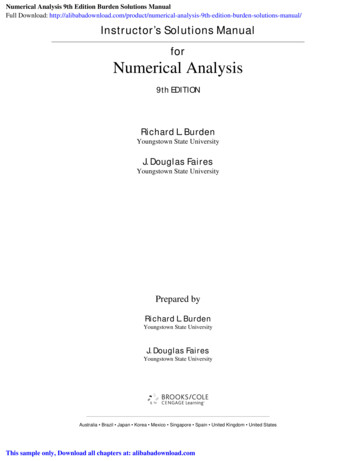
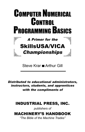
The aim of the numerical calculations was to determine the stress distributionin the model, for the vertical force P 15000 N, which is the maximum load thatcan move the scissor jack. The resulting reduced stress distributions, consistentwith the endurance hypothesis HMH (Huber-Mises-Hencky), were compared withthe material properties of the jack. Numerical calculations were carried out todetermine the strength of the mechanism.In the literature reference [9, 10] the author deals with an introduction to theinterface and a description of the program Abaqus and basic approach to designparts. The author also takes into account the approach to linear statics and togenerate an appropriate mesh type to designed objects.In the papers [4, 5] the authors deal with the presentation of a general approachto the problem of testing the strength of materials, through numerical modeling inAbaqus environment. The authors explain the idea of the work structure designbased on the study of stability.Through publications [11, 12, 13] it is possible to understand the Catiaenvironment and the practical use of knowledge on how to design and generatesimulation kinematic structure.In references [2, 7, 8] the authors dealt with issues related to research vehiclelifts, which is the necessary basis for the development of the issues describedin the present article. The publication [3] the author presents the problem of compression of thin-walled profiles are susceptible to loss of stability, which is closeto a submitted article.In [6] the authors take up the subject to generate 3D objects from 2D drawingsprepared in order to increase the potential of construction work and to improvethe design of machinery.2. MATERIALS AND METHODSThe subject of research was scissor jack BD-02B2. The mechanism is dedicated to passenger vehicles with an unladen weight not exceeding 1500 kg.In fact the lifting at the same time is one of the sides of car, so load is approximately only half the weight of the vehicle. Initial figure of model was designedin Catia V5R20 environment in which the simulation was also conductedkinematic, showing the correct operation of the jack and range of mobility.Numerical analysis was made using Abaqus 6.10. The mechanism was analyzednumerically, at maximum lift height of 345 mm.The jack is designed on the basis of measurements taken on a real object.The spatial model designed in CATIA, and the actual form of the scissor jack,shown in Figure 1.
a)b)Fig. 1. Scissor jack: a) mechanism made in Catia v5,b) the real form of mechanism [source: own research]The object of research was characterized by a uniform material properties.The mechanism is designed in accordance with the characteristics of the structuralsteel C45.The material of which made the scissor jack with its basic features of thematerial are shown in Table 1.
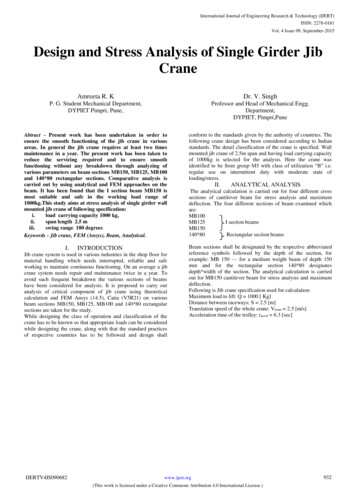
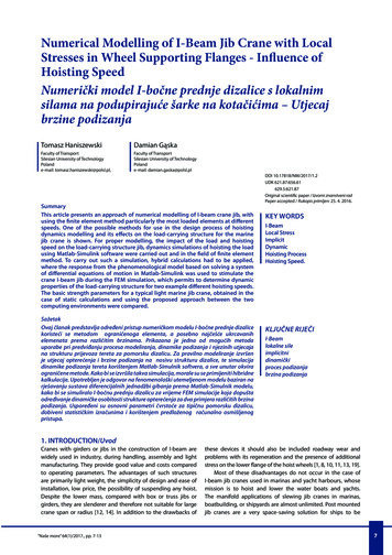
Tab. 1. Characteristics of the steel [1]Material: Steel C45Young's Modulus [Mpa]Poisson's RatioYield Strength [Mpa]Tensile Strength [Mpa]2100000.3360610Numerical calculations were based solely on static calculations, so the massof the mechanism were not taken into account. Any interactions prevailing in thesystem, were related only with contact on the tangential and normal direction withtaking into account the coefficient of friction of 0.15.The work of mechanism is performed by applying a vertical load to the crown,which acting in a downward direction in accordance with the X axis, and themechanism undergoes axial compression.Boundary conditions were associated with total restraint of base of the scissorjack, as well as the application of force concentrated at the reference point, whichis coupled with the upper planes of the crown of scissor jack, through use couplingconstraint in the interaction module, as shown in Figure 2.Fig. 2. Boundary conditions [source: own research]
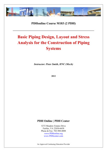
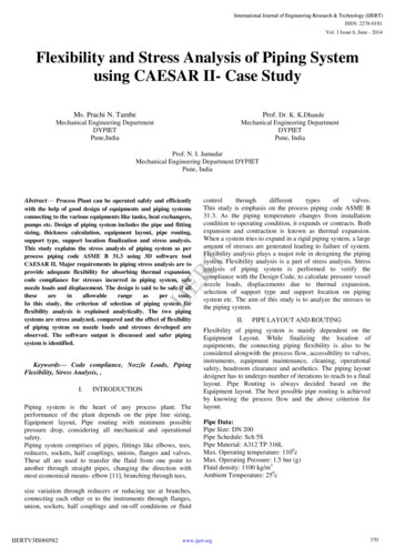
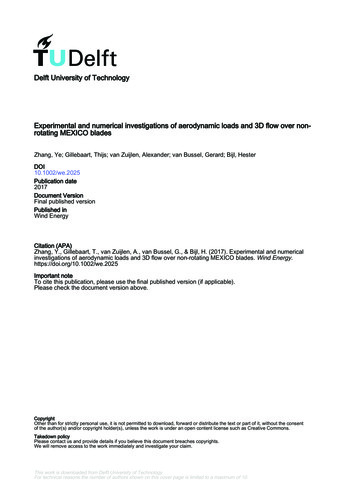
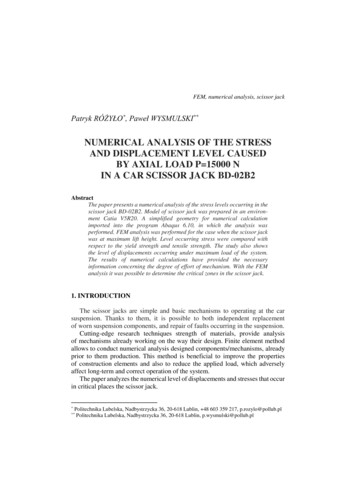
Proper conduct numerical simulation was made possible by assigning appropriateFEM mesh model. For this aim was used a tetrahedral elements called C3D4 andeight-node elements C3D8R with a reduced number of points of integration.Reduced integration technique removes the problem of irregular form of the deformation of objects. Eliminated are the components of higher order polynomials,which is beneficial to improve the results of numerical analysis performed [14].Finite element mesh was composed of more than 76000 items.The bolt, nut and screw guide element, are part which have a tetragonalstructure of mesh with a greater density, while all other components are assignedonly type hexagonal type of mesh by using the appropriate partitioning methods.Visualization of the generated mesh is shown in Figure 3.Fig. 3. The numerical model [source: own research]3. RESULTSFEM analysis made it possible to obtain a reduced stress distribution H-M-Hin the investigated mechanism. The most loaded part of the mechanism is screwguide element, in which the stress level was about 504 MPa. The remainder of themechanism to give the symmetric nature of stress distribution.Analysis showed a lack of exceed of strength border components, so the systemwill not be exposed to permanent damage. The level of stresses and displacementsshown in Figure 4.
a)b)c)Fig. 4. The results of numerical analysis: a) stress distribution in scissor jack,b) displacements occurring levels, c) maximum stress level [source: own research]
Only the screw guide element and nut have a stress exceeding the yield strength.In these parts there was a maximum of stress concentration occurred at the connection of these elements with arms of the scissor jack as shown in Figure 4c.The other components are not exposed to any loss of ductility. In fact, the emphasis generated by the weight of the vehicle, would be much lower, because israised only a part of the vehicle, so the level of stress would have much less.The paper presents the results of the analysis only with the maximum allowableload equal 15000 N and at maximum lift height equal to 345 mm. Any numericalcalculation was carried out taking into account the issues of non-lineargeometrically using the Newton-Raphson method.4. CONCLUSIONSOn the basis of the numerical analysis can draw the following conclusions:– analysis of the stress distribution allows to determine the sensitive zonesof mechanisms, which have the greatest concentration of stress in theindividual components and structural elements;– FEM analysis results showed no cross the border strength of the material,confirming the correctness of the designed system;– numerical research methods make it possible to further optimize thecomponents in terms of reducing the concentration of stresses and strains.In this study, showed no exceeding the maximum permissible strength of thematerial from which made the scissor jack. Only elements connecting the armsof scissor jack showed stress exceeding the yield strength at a given maximumemphasis.Application of FEM to analyze the stress distribution in the mechanismssubjected to loads, allows to take stress and strain state of this type of construction,which nowadays is indispensable in engineering applications. Numerical analyzesare now an essential tool in the market when tested the strength of materials, so itis possible to prevent an unnecessary manufacturing errors.REFERENCES[1][2][3]BANASZEK J.: Examples of calculations within machines constructions basics Part II.The University Publishing House, 1996, pp. 196–197.FENG L.: High Speed Elevator Car Frame’s Finite Elements Analysis. AdvancedMaterials Research, 2012, pp. 298–303.FERDYNUS M.: An energy absorber in the form of a thin-walled column with squarecross-section and dimples. Eksploatacja i Niezawodność – Maintenance and Reliability;Vol. 15, No. 3, 2013, pp. 253–258.
[4][5][6][7][8][9][10][11][12][13][14]KĄKOL W., ŁODYGOWSKI T.: Metoda elementów skończonych w wybranychzagadnieniach mechaniki konstrukcji inżynierskich. Politechnika Poznańska, 2003.KLEIBER M.: Wprowadzenie do metody elementów skończonych. Biblioteka MechanikiStosowanej IPPT PAN, PWN, Warszawa-Poznań, 1985.LONKWIC P., BOROWIK Ł.: Przejście 2D do 3D – zwiększenie potencjału konstruktora.Obróbka Metalu, No. 3, 2011.LONKWIC P., GARDYŃSKI L.: Testing polymer rollers memory in the context ofpassenger lift car comfort. Journal of Vibroegineering, 2014, Vol. 1, pp. 225–230.ONUR Y. A., IMRAK C. E.: Reliability analysis of elevator car frame using analyticaland finite element methods. Building Services Engineering Research & Technology;Vol. 33, No. 3, 2011, pp. 293–305.VENKATESH C.: Getting Started with Abaqus – Workbook 0: User Interface and ModelingOverview, 2011.VENKATESH C.: Getting Started With Abaqus – Workbook 1: Linear Static Analysesand Basic Mesh Generation, 2012.WEŁYCZKO A.: CATIA V5. Przykłady efektywnego zastosowania systemu w projektowaniumechanicznym, 2005.WYLEŻOŁ M.: Modelowanie bryłowe w systemie CATIA. Przykłady i ćwiczenia, 2002.WYLEŻOŁ M.: Catia v5. Modelowanie i analiza układów kinematycznych, 2007.ZIENKIEWICZ O.C., TAYLOR R.L.: Finite Element Method (5th Edition), Vol. 2 – SolidMechanics, 2000, Elsevier.
Fig. 1. Scissor jack: a) mechanism made in Catia v5, b) the real form of mechanism [source: own research] The object of research was characterized by a uniform material properties. The mechanism is designed in accordance with the characteristics of the structural steel C45. The material of which made the scissor jack with its basic features of the