Transcription
Subject code : CE 2401Name of the subject : DESIGN OF REINFORCEDCONCRETE & BRICK MASONRY STRUCTURESDate of deliverance :ChapterReference details :VSA Educational and CharitableDesignof RCTrust’sElements,Group of Institutions, Salem – 636 010Mr. N . krishnarajuDepartment of Civil EngineeringUnit II – water tankUnderground rectangular tanks – Domes – Overhead circular and rectangular tanks – Design of staging andfoundations-DesignDesign as per BIS Codal Provisions.Aim:underwater tank, dome & over head circular and rectangular tankAs per the IS Code requires undergroundwith staging and foundation to be designed to ensure stability and satisfies the BIS codal provisions.WATER TANKSIn general there are three kinds of water tanks-tanks resting on ground, underground tanks andelevated tanks.The tanks resting on ground like clear water reservoirs, settling tanks, aeration tanks etc. aresupported on the ground directly. The walls of these tanks are subjected to pressure and the base issubjected to weight of water and pressure of soil. The tanks may be covered on top.The tanks like purification tanks, Imhoff tanks, septic tanks, and gas holders are built underground.The walls of these tanks are subjected to water pressure from inside and the earth pressure from outside.The base is subjected to weight of water and soil pressure. These tanks may be coveredred at the top.Elevated tanks are supported on staging which mayay consist of masonry walls, R.C.C. tower orR.C.C. columns braced together.gether. The walls are ssubjected to water pressure.re. The base has to carry the loadof water and tank load. The staging has to carry load of water and tank. The staging is also designed forwind forces.From design point of view the tanks may be classified as per their shape-rectanrectangular tanks, circulartanks, intze type tanks. Spherical tanks conical bottom tanks and suspended bottom tanks.Design requirement of concreteIn water retaining structures a dense impermeable concrete is required thereforre, proportion of fineand course aggregates to cementent should be such as to give high quality concrete.Concrete mix weaker than M200 is not used. The minimum quantity of cementent in the concrete mix3shall be not less than 300 kg/m .The design of the concrete mixx shall be such that the resultant concrete is sufffficiently impervious.Efficient compaction preferably by vibrationvibris essential. The permeability of thee thoroughly cocompactedconcrete is dependent on water cementent ratio. Increase in water cement ratio increaseses permeability, whileconcrete with low water cement ratio is difficult to compact.pact. Other causes of leakage in concrete aredefects such as segregation and honey combing. All joints should be madeade waterwater-tight as these arepotential sources of leakage.Prepared by Mr.R.YUVARAJA,, Assistant Professor / CivilPage 1
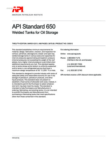
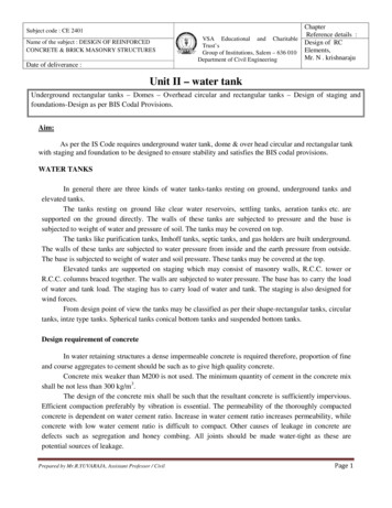
Subject code : CE 2401Name of the subject : DESIGN OF REINFORCEDCONCRETE & BRICK MASONRY STRUCTURESDate of deliverance :ChapterReference details :VSA Educational and CharitableDesignof RCTrust’sElements,Group of Institutions, Salem – 636 010Mr. N . krishnarajuDepartment of Civil EngineeringDesign of liquid retaining structures is different from ordinary R.C.C, structures as it requires thatconcrete should not crack and hence tensile stresses in concrete should be within permissibleissible limits.liA reinforced concrete membermber of liquid retainingtaining structures is designed on the usual principlesignoring tensile resistance of concrete in bending. Additionally it should be ensured that tensile stress onthe liquid retaining face of the equivalealent concrete section does not exceed the permissibleissible tensile strengthof concrete as given in table1. For calculation purposes the cover is also taken into concrete area.Cracking may be caused due to restraint to shrinkage, expansion and contraction of concrete ddue totemperature or shrinkage and swellingelling due to moisture effects. Such restraint mayay be caused by –(i)The interaction between reinforcement and concrete during shrinkage due to drying.(ii)The boundary conditions.(iii) The differential conditionsconditiprevailing through the large thickness of massive concrete.Use of small size bars placed properly, leads to closer cracks but of smalleraller width. The risk ofcracking due to temperatureperature and shrinkage effects may be minimized by limitingiting the changes in moisturecontent and temperature to which the structure as a whole is subjected. The risk of cracking can alsobe minimized by reducing the restraint on the free expansion of the structure with long walls or slabfoundedd at or below ground level, restraint can be minimized by the provision of a sliding layer. This canbe provided by founding the structure on a flat layer of concrete with interposition of some material tobreak the bond and facilitate movement.ent.In case length of structure is large it should be subdivided into suitable lengths separatedseparby movement joints, specially where sections are changed the movement jointsints should be provided.Where structures have to store hot liquids, stresses caused by difference in tetemperature betweeninside and outside of the reservoirservoir should be taken into account.accouThe coefficient of expansion due to temperature change may be taken as 11 x 10-6/ C-6-6and coefficient of shrinkage may be taken as 450 x 10 for initial shrinkage and 200 x 10 for dryingshrinkage.3. Joints in Liquid Retaining Structurectures. Joints are classified as given below.(a)Movement Joints. There are three types of movement joints.(i)Contraction Joint. It is a movement joint with deliberate discontinuityity without initial gapbetween the concrete on either side of the joint. The purpose of this joint is to accommmodate contraction ofthe concrete. The jointint is shown in Fig. 1(a).1(Prepared by Mr.R.YUVARAJA,, Assistant Professor / CivilPage 2
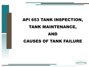
ChapterReference details :VSA Educational and CharitableDesignof RCTrust’sElements,Group of Institutions, Salem – 636 010Mr. N . krishnarajuDepartment of Civil EngineeringSubject code : CE 2401Name of the subject : DESIGN OF REINFORCEDCONCRETE & BRICK MASONRY STRUCTURESDate of deliverance :(a)(b)Fig 1.A contraction joint may be eithereith complete contraction jointint or partial contractioncjoint. Acomplete contraction joint is one in which both steel and concrete are interrupted and a partialcontraction joint is one in which only tthe concrete is interrupted, the reinforcing steell running through asshown in Fig. 1(b).(ii)Expansion Joint. It is a joint with complete discontinuity in both reireinforcing steel andconcrete and it is to accommodate eithher expansion or contraction of the structure. A typical expansionjoint is shown in Fig. 2.Fig. 2This type of joint requires the provision of an initial gap between the adjoining parts of a structurewhich by closing or opening accommodmmodates the expansion or contractiontion of the structure.(iii)Sliding Joint. It is a jointjoi with complete discontinuity in both reinforceorcement and concreteand with special provision to facilitate movement in plane of the joint. A typical jointint is shown in Fig. 3.This type of joint is providedovided between wall and floor in someso cylindrical tank designs.(b)Construction Joint. Thishis type of joint is provided for convenience in construction.Arrangement is made to achieveve subsequent continuity without relative movement.mov ent. One applicationPrepared by Mr.R.YUVARAJA,, Assistant Professor / CivilPage 3
Subject code : CE 2401Name of the subject : DESIGN OF REINFORCEDCONCRETE & BRICK MASONRY STRUCTURESDate of deliverance :ChapterReference details :VSA Educational and CharitableDesignof RCTrust’sElements,Group of Institutions, Salem – 636 010Mr. N . krishnarajuDepartment of Civil Engineeringof these joints is between successive liffts in a reservoir wall. A typical jointint is shown in Fig. 4.RCPARED SILDING SURFACEOR RUBBER PAOFig.33Fig.4The number of joints should be as smmall as possible and these joints should be kept from possibility ofpercolation of water.(c)Temporary Open Joints.Joints A gap is sometimes left temporarily betwetween the concrete ofadjoining parts of a structure whichFig. 5 Temporary open jointsafter a suitable interval and before the structurestructis put to use, is filled with mortar or concconcrete completely asin Fig. 5(a) or as shown in Fig. 5 (b) and (c) with suitable jointing materials. In the firsst case width of thegap should be sufficient to allow the sides to be prepared before filling.Prepared by Mr.R.YUVARAJA,, Assistant Professor / CivilPage 4
Subject code : CE 2401Name of the subject : DESIGN OF REINFORCEDCONCRETE & BRICK MASONRY STRUCTURESDate of deliverance :ChapterReference details :VSA Educational and CharitableDesignof RCTrust’sElements,Group of Institutions, Salem – 636 010Mr. N . krishnarajuDepartment of Civil EngineeringSpacing of Joints. Unless alternative effective means are taken to avoid cracks by allowing for theadditional stresses that may be induced by temperature or shrinkage changes or by unequal settlesettlement,movementent joints should be provided at the following spacings:spacings:(a)In reinforced concrete floors, movement joints should be spaced at not more than 7.5 mapart in two directions at right angles. The wall and floor joints should be in line except where slidingjoints occur at the base of the wall in which correspondencecis not so important.(b)For floors with only nominalnopercentage of reinforcement (smaller than the minimumspecified) the concrete flooroor should be cast in panels with sides not more than 4.5 m. (c)In concretewalls, the movement joints should normally be placed at a maximum spacing of 7.5 m. inreinforced walls and 6m. in unreinforced walls. The maximum length desirablerable between verticalmovement joints will depend upon the tensile strength of the walls, and may be increased by suitablereinforcement. When a sliding layer is placed at the foundation of a wall, the length of the wall thatcan be kept free of cracks depends on the capacity of wall section to resist the frictionriction induced at theplane of sliding. Approximately the wall has to stand the effect of a force at the place of sliding equal toweight of half the lengthefficient of friction.of wall multiplied by the co-efficient(d)Amongst the movemeent joints in floors and walls as mentionedentioned above expansionjoints should normally be provided at a spacing of not more than 30 m. betweensuccessiveve expansion joints or between the end of the structure and the next expansion joint; all otherjoints being of the construction type.(e)When, however, the temmperaturere changes to be accommodated are abnorabnormal or occur morefrequently than usual as in the case of storage of warm liquids or in uninsulated roof slabs, a smallerspacing than 30 m should be adopted, that is greater proportion of movementent joints should be of theexpansion type). Whenhen the range of temperature is small,sfor example,ple, in certain cocovered structures, orwhere restraint is small, for example,ple, in certain elevated structures none of the movemment joints providedin small structures up to 45m. length need be of the expansion type. Where slidinging joints are providedbetween the walls and either the floor or roof, the provision of movement joints in each element can beconsidered independently.4.General Design for Requirements (I.S.I)1.Plain Concrete Structures. Plain concrete member of reinforced concrete liquidretaining structures may be designed against structural failure by allowing tension in plain concrete asper the permissible limitsits for tension in bending.beThis will automaticallyatically take care of failure due tocracking. However, nominal reinforcemment shall be provided, for plain concrete structural members.Prepared by Mr.R.YUVARAJA,, Assistant Professor / CivilPage 5
Subject code : CE 2401Name of the subject : DESIGN OF REINFORCEDCONCRETE & BRICK MASONRY STRUCTURESDate of deliverance :ChapterReference details :VSA Educational and CharitableDesignof RCTrust’sElements,Group of Institutions, Salem – 636 010Mr. N . krishnarajuDepartment of Civil Engineering2. Permissible Stresses in Concrete.(a)For resistance to cracking.cking. For calculations relating to the resistaance of members tocracking, the permissible stresses in tension (direct and due to bending) and shear shall confirm to thevalues specified in Table 1. The permmissible tensile stresses due to bending apply to the face of themember in contact with the liquid. In membersmless than 225 mm. thick and in contact with liquid on oneside these permissibleissible stresses in bending apply also to the face remoterefrom the liquid.uid.(b)For strength calculations.calculatiIn strength calculations the permissibleissible concrete stressesshall be in accordance with Table 1. Where the calculated shear stress in concrete alone exceeds thepermissible value, reinforcementent acting in conjunction with diagonal compressionpression in the concrete shall beprovidedded to take the whole of the shear.Table 1Permissibleble concrete stresses in calculations relating to resistancere istance to crackingGrade of concreteM 150M 200M 250M 300M 350M 4003.Permissibleissible stress in kg/cm2TensionDue toDirectBending111512171318152016221724Shear ( Q/bjdQ/bjd)151719222527Permissible Stresses in Steel(a)For resistance to cracking.cking. When steel and concrete are assumeded to act together forchecking the tensile stress in concrete for avoidance of crack, the tensile stress in steeel will be limited bythe requirement that the permissible tensile stress in the concrete is not exceeded so the tensile stress insteel shall be equal to the product of modularmratio of steel and concrete, and the corresponding allowabletensile stress in concrete.(b) For strength calculationss. In strength calculations the permissible stress shall be as follows:(i)(ii)Tensile stress in memberber in direct tensionTensile stress in membber in bending on liquid retainingface of membersmbers or face away ffrom liquid for members less than225 mm thick.Prepared by Mr.R.YUVARAJA,, Assistant Professor / Civil1000 kg/cm21000 kg/cmkg/c 2Page 6
Subject code : CE 2401Name of the subject : DESIGN OF REINFORCEDCONCRETE & BRICK MASONRY STRUCTURESDate of deliverance :(iii)(iv)ChapterReference details :VSA Educational and CharitableDesignof RCTrust’sElements,Group of Institutions, Salem – 636 010Mr. N . krishnarajuDepartment of Civil EngineeringOn face away from liquid for members 225 mm. or more inthickness.Tensile stress in shearr reinforcement,rFor members less than225 mm thicknessFor membersmbers 225 mm or more in thicknessCompressivepressive stress in columnscolusubjected to direct load.1250 kg/cmkg/c 21000 kg/cmkg/c 21250 kg/m21250 kg/cm2Note 1. Stress limitations foror liquid retaining faces shall also apply to:(a)(b)Other faces within 225 mm of the liquid retaining face.Outside or external faces of structures away from the liquid but placed in water loggedsoils upto the level of highest subsoil water level.Note 2. The permissible stress of 1000 kg/cm2 in (i), (ii) and (iii) may be incrincreased to21125 kg/cm in case of deformed bars and in case of plain mild steel bars when the crossreinforcement is spot welded to the mainain reinreinforcement.4.Stresses due to drying Shrinkageinkage or Temperature Change.(i)Stresses due to drying shrinkage or temperature change may be ignored providedthat –(a)the permissible stresses specified above in (ii) and (iii) are not otherwise exceeded.(b)adequate precautionstions are taken to avoid cracking of concrete during theconstruction period and until the reservoir is put into use.(c)recommendation regarding joints given in article 8.3 and for suitable sliding layerbeneath the reservoir aree compliedcowith, or the reservoir is to be used only for the storageof water or aqueous liquidsliquat or near ambient temperature and the circucircumstances aresuch that the concreteoncrete will never dry out.o(ii)Shrinkage stresses mayay however be required to be calculated in special cases, when ashrinkage co-efficientefficient of 300 x 110-6 may be assumed.(iii) When the shrinkage stressessare allowed, the permissible stresses, tensile stresses toconcrete (direct and bending) as given in Table 1. may be increased by 33 per cent.5.Floors(i))articleProvision of movement joints. Movement joints should be provided as discussed in3.(ii)Floors of tanks resting on ground. If the tank is resting directly over ground, floor maybe constructed of concrete with nominnal percentage of reinforcement provided that it is certain that theground will carry the load without appreciablereciable subsidence in any part and that the concrete floor is cast inpanels with sides not more than 4.5 m. with contraction or expansion joints between. In such cases aPrepared by Mr.R.YUVARAJA,, Assistant Professor / CivilPage 7
Subject code : CE 2401Name of the subject : DESIGN OF REINFORCEDCONCRETE & BRICK MASONRY STRUCTURESDate of deliverance :ChapterReference details :VSA Educational and CharitableDesignof RCTrust’sElements,Group of Institutions, Salem – 636 010Mr. N . krishnarajuDepartment of Civil Engineeringscreed or concrete layer less than 75 mm thick shall first be placed on the ground and covered with asliding layer of bitumen paper or other suitable material to destroy the bond betwween the screed andfloor concrete.In normal circumstances the screed layer shall be of grade not weaker than M 100, whereinjurious soils or aggressive water are expected,ethe screed layer shall be of grade not weaker than M 150and if necessary a sulphate resisting or other special cement should beused.(iii)Floor of tankss resting on supports(a)If the tank is supported on walls or oother similarilar supports the floor slab shall be designed asfloor in buildings for bending momentsnts due to water load and self weight.(b)When the floor is rigidly connected to the walls (as is generally the case) the bendingmoments at the junction between thee walls and floors shall be taken into account in the design of floortogether with any direct forces transferred to the floor from the walls or from the floorloor to the wall due tosuspension of the floor from the wall. If the walls are non-monolithic with the floor sllab, such as in cases,where movement joints have been providedprovibetween the floor slabs and walls, the floor shall bedesigned (only for the vertical loads on the floor.(c)In continuous T-beamss and L-beams with ribs on the side remote from the liquid, thetension in concrete on the liquid side at the face of the supports shall not exceed the permissibleperstressesfor controlling cracks in concrete. The width of the slab shall be determinedined in usual manner forcalculation of the resistance to crackingg of T-beam,TL-beam sections at supports.(d)The floor slab may be suitably tied to the walls by rods properly embeddedbedded in both the slaband the walls. In such cases no separaterate beam (curved or straight) is necessary under the wall, providedthe wall of the tank itself is designed to act as a beam over the supports under it.(e)Sometimes it may be economicaleconoto provide the floors of circular tanks, in the shape ofdome. In such cases the dome shall be designed for the vertical loads of the liquid over it and the ratioof its rise to its diameter shall be so adjusted that the stresses in the dome are, as far as possible, whollycompressive. The dome shall be supported at its bottom on the ring beam which shall be designed forresultant circumferential tension in addition to vertical loads.6.Walls(i)Provision of Joints(a)Sliding joints at the baase of the wall. Where it is desired to allow the walls to expand orcontract separately from the floor, or to prevent moments at the base of the wall owing to fixity to thefloor, sliding joints may be employed.(b)The spacing of vertical movement joints should be as discussed in article 8.3 while themajority of these joints may be of the partial or complete contraction type, sufffficient joints of theexpansion type should be provided to satisfy the requirements given in articlePrepared by Mr.R.YUVARAJA,, Assistant Professor / CivilPage 8
Subject code : CE 2401Name of the subject : DESIGN OF REINFORCEDCONCRETE & BRICK MASONRY STRUCTURESDate of deliverance :ChapterReference details :VSA Educational and CharitableDesignof RCTrust’sElements,Group of Institutions, Salem – 636 010Mr. N . krishnarajuDepartment of Civil Engineering(ii)Pressure on Walls.(a)In liquid retaining structuresstrwith fixed or floating covers the gas pressure developedabove liquidd surface shall be added to the liquid pressure.(b)When the wall of liquid retaining structure is built in ground, or has earth embankedagainstgainst it, the effect of earth pressure shall be taken into account.(iii)Walls or Tanks Rectanngular or Polygonal in Plan.While designing the walls of rectangular or polygonal concrete tanks, the following points should beborne in mind.a) In plane walls, the liquid pressure is resisted by both vertical and horizontal bending moments. Anestimate should be made of the proportion of the pressure resisted by bending moments in thevertical and horizontal planes.anes. The direct horizontal tension caused by the direct pull due to waterpressure on the end walls, should be added to that resulting from horizontaltal bending moments. Onliquid retaining faces, the tensile stresses due to the combination of direct horizontal tension andbending action shall satisfy the following conditionwheret'tσ′ctσct calculated direct tensile stress in concrete. permissibleissible direct tensile stress in concrete (Table 1) calculated tensile stress due to bending in concrete. permissibleissible tensile stress due to bending in concrete.(d)At the vertical edges where the walls of a reservoir are rigidlyidly joined, horizontalreinforcementent and haunch bars should be provprovidedded to resist the horizontal bending momentsmoeven if thewalls are designed to withstand the whole load as vertical beams or cantilever without lateral supports.(c)In the case of rectangular or polygonal tanks, the side walls act as two-way slabs,whereby the wall is continued or restrained in the horizontal direction, fixed or hinged at the bottom andhinged or free at the top. The walls thus act as thin plates subjected triangular loading and withboundary conditions varying between full restraint and free edge. The analysis of momoment and forcesmay be madeade on the basis of any recognized method.(ii) Walls of Cylindrical Tanks.Tanks While designing walls of cylindrical tankstthe followingpoints should be borne in mind:(a)Walls of cylindrical tanks are either cast monolithically with the base or are set ingrooves and key ways (movement joints). In either case deformation of wall under influence of liquidpressure is restricted at and above the base. Consequently, only part of the triangular hydrostatic load willbe carried by ring tension and part of thhe load at bottom will be supported by cantilever action.(b)It is difficult to restrict rotationror settlement of the base slab and it is advisable to providePrepared by Mr.R.YUVARAJA,, Assistant Professor / CivilPage 9
Subject code : CE 2401Name of the subject : DESIGN OF REINFORCEDCONCRETE & BRICK MASONRY STRUCTURESDate of deliverance :ChapterReference details :VSA Educational and CharitableDesignof RCTrust’sElements,Group of Institutions, Salem – 636 010Mr. N . krishnarajuDepartment of Civil Engineeringvertical reinforcement as if the walls were fully fixed at the base, in addition to thee reinforcereinforcement requiredto resist horizontal ring tension for hinged at base, conditions of walls, unless the appropriate aamount offixity at the base is established by analysis with due consideration to the dimensions of the base slab thetype of joint between the wall and slab,and, where applicable, the type of soil supporting the base slab.7.RoofsmpatheticMoveme Joints. To avoid the possibility of sym(i)Provision of Movementcracking it is important to ensure that movementmjoints in the roof correspond with those in thewalls, if roof and walls are monolithic.onolithic. It, however, provision is made by means of a sliding joint formovementent between the roof and the wall correspondence of joints is not so important.(ii)Loading. Field covers of liquid retaining structures should be designed for gravityloads, such as the weight of roof slab, earth cover if any, livee loads and mechanical equipment.equipTheyshould also be designed for upwardrd load if the liquid retaining structure is subjected to internal gaspressure.A superficial load sufficient to ensure safety with the unequal intensityity of loading whichoccurs during the placing of the earth cover should be allowed for in designing roofs. The engineershould specify a loading under these temporaryteconditions which should not be exceeded. In designingthe roof, allowance should be made for the temporary condition of some spans loaded and other spansunloaded, even though in the final state the load may be small and evenly distributed.(iii)Water tightness. In case of tanks intended for the storage of water for domesticpurpose, the roof must be made water-tight.tight. This may be achieved by limitingiting the stresses as for the rest ofthe tank, or by the usee of the covering of the waterproof membrane or by providing slopes to ensureensadequate drainage.(iv)Protection against corrosion.corrosio Protection measure shall be provided to tthe underside of theroof to prevent it from corrosion due to condensation.8. Minimum Reinforcement(a)The minimum reinforcorcement in walls, floors and roofs in each of two directions at rightangles shall have an area of 0.3 per cent of the concrete section in that direction for sections upto 100 mm,thickness. For sections of thickness greater than 100 mm, and less than450 mm the minimum reinforcement in each of the two directions shall be linearly reduced from 0.3percent for 100 mm. thick section to 0.2 percent for 450 mm, thick sections. For sections of thicknessgreater than 450 mm, minimum reinfoeinforcement in each of the two directions shall be kept at 0.2 percent. In concrete sections of thicknesskness 225 mm or greater, two layers off reinforcement steel shall beplaced one near each face of the section to make up the minimum reinforcement.(b)In special circummstances floor slabs may be constructed with percentage ofPrepared by Mr.R.YUVARAJA,, Assistant Professor / CivilPage 10
Subject code : CE 2401Name of the subject : DESIGN OF REINFORCEDCONCRETE & BRICK MASONRY STRUCTURESDate of deliverance :ChapterReference details :VSA Educational and CharitableDesignof RCTrust’sElements,Group of Institutions, Salem – 636 010Mr. N . krishnarajuDepartment of Civil Engineeringreinforcement less than specified above. In no case the percentage of reinforcement in any member isless than 0 15%15% of gross sectional area of the member.9.Minimum Cover to Reinforcemement.(a)For liquid faces of parts of members either in contact with the liquid (such as inner faces orroof slab) the minimum cover to all reinforcement should be 25 mm or the diametereter of the main barwhichever is grater. In the presence of the sea water and soils and water of corrosive characters the covershould be increased by 12 mm but this additional cover shall not be taken into account for designcalculations.ntact with the liquid(b)For faces away from liquid and for parts of the structure neither in conton any face, nor enclosing the spacee above the liquid, the cover shall be as for ordinary concrete member.5. Tanks Resting on Ground. For small capacities rectangular tanks are generally used and forbigger capacities circular tanks aree used. The walls of circular tanks may have flexiblelexible joijoints or rigid jointsat the base.6. Ciruclar Tanks with Flexible Joint at the Base.In these tanks walls are subjected tohydrostatic pressure. The tanknk wall is designed as thin cylinder.At the base, minimum pressure wH.This causes hoop tensionwHD 2where2 1000w is the density ofwater. H is depthof water, and D isdiameter of thetankSteel area required at the base for one metre heightwHD cm 2If 't' is the thickness of wall, tensile stress in concretewHD / 2kg / cm 2 100t (m 1) AtPrepared by Mr.R.YUVARAJA,, Assistant Professor / CivilPage 11
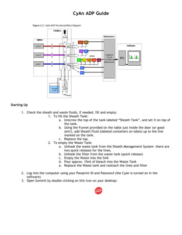
Subject code : 080100048Name of the subject : DESIGNOF RC STRUCTURESDate of deliverance :VSA Educational and Charitable Trust’s Group of Institutions,Salem – 636 010Department of Civil EngineeringChapterReference details :Design of rcelements,Mr. N . krishnarajuAs the hoop tension reduces gradually to zero at top, the reinforcementent is graduallyreduced to minimum reinforceinforcement at top. The main reinforcementent consists of circularhoops Vertical reinforcement equal to 0.3% of concrete area is providedovided and hoopreinforcement is tied to this reineinforcement. In smaller tanks main reinforcementement is placednear the outer face.ace. For bigger tanks the wall thickness is more and the reinforcereinforcement isplaced on both faces.Though assumed that base is flexible, but in reality there will always be somerestraint at the base and somee pressurep essure will be resisted by cantilever action of the wall. TTheminimum vertical reinforcementent provided willw be adequate to resist bending stresses causedby cantilever action.Example 1.DESIGN OF UNDERGROUND WATER TANKPrepared by Mr.R.YUVARAJA,, Assistant Professor / CivilPage 12
Subject code : 080100048Name of the subject : DESIGNOF RC STRUCTURESDate of deliverance :VSA Educational and Charitable Trust’s Group of Institutions,Salem – 636 010Department of Civil EngineeringPrepared by Mr.R.YUVARAJA,, Assistant Professor / CivilChapterReference details :Design of rcelements,Mr. N . krishnarajuPage 13
Subject
against structural failure by allowing tension nding. This will automatically take care ent shall be provided, for plain concrete structural Chapter Reference details : Design of RC Elements, Mr. N . krishnaraju Page 5 for the ment, more tha