Transcription
New Contact Addressin-tech smart charging GmbHImportant noticeDear customer,in-tech smart charging GmbH is expanding. From now on we will be based inBitterfelder Str. 1-5 in 04129 Leipzig.Our email address smartcharging@in-tech.com and phone number 49 34139290250 remain unchangend.As of now mail will be received at the new address.Yours sincerely,in-tech smart charging GmbH1
Charge Control M User Guidein-tech smart charging GmbHAug 27, 2021
Charge Control M User GuideContents1Revision . 12Safety Notes. 13Abbreviations . 14Introduction . 25Device Overview . 35.1Mechanical dimensions . 35.2LEDs . 45.3Connectors . 55.4Voltage Input (X4) . 65.5Network interfaces . 66Programming . 76.1Device Access . 86.2Logging and Debugging . 87Firmware upgrade . 87.1Partitioning . 97.2Update via USB . 97.3Update via SSH and SFTP . 107.4Update via SSH or Serial Console and HTTP or FTP . 107.5Update via MQTT API . 117.6Support for casync based Firmware Updates . 137.7Rollback mechanism . 148General charging software description . 168.1Charging states . 168.2Connection status . 178.3EVSE Processing . 178.4Configuration and initialization of the charging software . 189MQTT and Mosquitto Documentation . 229.1MQTT Interface and Configuration . 229.2MQTT Service Discovery . 229.3Topic level architecture . 239.4MQTT Topics . 24
Charge Control M User Guide9.5Physical value type . 619.6Relations between topics and SECC configuration . 619.7Stop charging and error shutdown on EVSE side . 629.8Renegotiation process (ISO 15118 specific) . 629.9Plug and Charge (ISO 15118 specific) . 639.10Value Added Services . 659.11Best practice for DC Charging . 659.12Programming example to handle specific topics on charger side . 6710CAN Interface Documentation . 7010.1EVSE Controller Messages . 7010.2Description of parameters per charging state . 9010.3Stop charging and error shutdown indication on EVSE side . 9911Order Information . 9912Contact . 99
Charge Control M User Guide1 RevisionRevisionRelease DateValid from Software Version Changes127.08.20210.9.7initial releaseThank you very much for your trust. We are happy that you have chosen our Charge Controlplatform to operate your eMobility charging solution. This User Guide will help you to understandall features of our product and configure them properly to fit your and your customer’srequirements best.2 Safety NotesIMPORTANT: Read the following safety instruction carefully and clearly prior to the assembly anduse of the device.Please keep these safety instructions for future reference.The installation and assembly may only be carried out by a qualified electrician!This device, which is supplied with mains power, has to be secured by means of a max.B6A circuit breaker.WARNING! This device is connected to mains power and hazardous voltages which are notcovered. Hazardous voltages must be covered inside the charging station to prevent electricalshocks.Attention! Make sure that the device is not exposed to heat sources which may lead tooverheating. Charge Control M can be damaged in case of overheating.Attention! The device may only be connected in the range of overvoltage category 3 or lower.Operating Charge Control M in a higher category can damage the device.Attention! Ensure adequate ventilation at the site of installation. Charge Control M can bedamaged in case of overheating.Attention! Do not operate the device in supply networks which do not comply with thespecifications on the type plate. Operating Charge Control M in networks not compatible with thespecifications on the type plate can damage the device.Attention! The device may only be installed in dry areas. Exposing Charge Control M to wetnesscan damage the device.This device is designed for installation on DIN rails which provide fire protection as per DIN EN60950-1.3 AbbreviationsCommon abbreviations used throughout the document or related to charging.AbbreviationMeaningCANController area networkCPControl pilotEVElectric vehicleEVCCElectric vehicle communication controller1
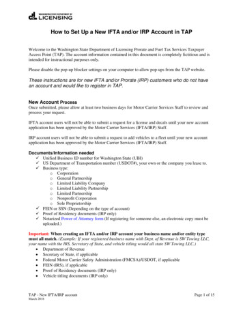
Charge Control M User GuideEVSEElectric vehicle supply equipmentJSONJavaScript object notationMQTTMessage queuing telemetry transportPEProtective earth conductorPKIPublic key infrastructurePLCPowerline communicationPnCPlug and chargePPProximity pilotPWMPulse width modulationRCDResidual-current deviceSDPSECC discovery protocolSECCSupply equipment communication controllerTCPTransmission control protocolTLSTransport layer securityHLCHigh-level charging communicationV2GVehicle to grid communication4 IntroductionCharge Control M is a DIN 70121 and ISO 15118 compliant communication controller for DCelectric vehicle charging stations (EVSE side). It is based on in-tech smart charging's ownEVAcharge SE hardware platform which includes PWM generation on Control Pilot line, and alsoa HomePlug Green PHY integration and thus Powerline communication via Control Pilot for HighLevel charging communication. The Charge Control M firmware is powered by an embeddedLinux operating system. Customers can use an MQTT API or a CAN interface to interact with thefirmware. The open system offers customers the possibility to extend the Charge Control Mfirmware and even run customer's own software component in parallel to the charging stack.Highlights: CPU: NXP i.MX287 (formerly Freescale) RAM: 128 MiB Storage: eMMC 4 GiB Network Interface: Fast Ethernet Operating System: Embedded Linux, based on Yocto, Kernel 4.9 (or newer) Charging Protocols: IEC 61851, DIN 70121, ISO 15118 Charge Process Controlling Interfaces: MQTT, CANParameterValuePower supply12 VPower consumption max. 4 W (2.6 W in idle mode) - plus power for attached USB devicesTemperature range-40 C - 85 C2
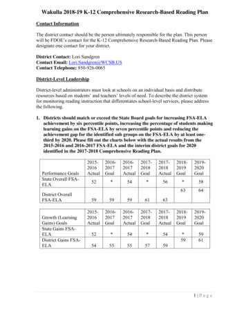
Charge Control M User GuideAir humidity95% rel. humidity (non condensing)Outline dimension100 mm x 120 mm x 20 mmWeight92 gRoHSCharge Control M is manufactured RoHS compliant.Figure 1 Charge Control M Big Picture5 Device Overview5.1 Mechanical dimensionsThe mechanical dimensions of the Charge Control M are shown in figure mechanical drawing.Figure 2 Mechanical Drawing of Charge Control M including Connectors3
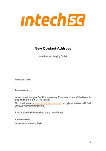
Charge Control M User Guide5.2 LEDsFigure 3 LEDs on EVSE5.2.1 LED0 (red)The LED is connected to the i.MX28 pin K4 / AUART1 TX. Default behaviour is the Linuxheartbeat of the i.MX28.5.2.2 LED1 (yellow)The LED is connected to the i.MX28 pin L4 / AUART1 RX.5.2.3 LED2 (yellow)The LED is connected to the i.MX28 pin T3 / LCD D16.5.2.4 LED3 (green)The LED is connected to the i.MX28 pin P2 / LCD D08.5.2.5 LED4 (yellow)The USS command indicator of the coprocessor. Each time an USS command is received by thehost and processed, the LED flashes for a short time. If the coprocessor stays in bootloader(immediately after reset for a few seconds) this LED is always on.4
Charge Control M User Guide5.2.6 LED5 (green)The coprocessor life sign. The LED blinks in a one second interval showing the coprocessor isworking and alive. If the coprocessor stays in bootloader (immediately after reset for a fewseconds) this LED is always off.5.3 ConnectorsFigure 4 ConnectorsDebug UART (JP1)Figure 5 Debug UART in detailThis pinout is compatible with a variety of USB/RS232 adapters. Preferable you should use theFTDI cable ”TTL-232R-3V3” or similar, do not use long wires to connect the debug UART.5
Charge Control M User GuideATTENTION: Do not use generic RS232 adapters, as they usually have -12 V voltages for theirlogic signals. The pins here are only 3.3 V tolerant. You may damage the debug UART withincompatible adapters.Use the following settings to connect to the debug UART:SettingValueBaud Rate115200Data bits8Stop bits1ParityNoneFlow ControlNone5.4 Voltage Input (X4)Figure 6 Voltage input connectorThis connector is Metz Connect (formerly Ria Connect) 31177102 (Series 177). The wire for thepower supply does not need to be a specific length or cross-section. You should make sure thatthe cross-section fits the connector you choose and the length does not add too much voltagedrop.5.5 Network interfacesThe default Charge Control M network configuration creates a virtual Ethernet bridge br0consisting of the wired Ethernet interface eth0 and -if available- the USB dongle for mobilebroadband communication.This bridge interface ships with DHCP enabled by default, plus a static fallback IPv4 address inthe AutoIP network range (see RFC3927) to ease access in direct connections with MicrosoftWindows PCs. The MAC address of the bridge interface corresponds to the MAC address ofthe wired Ethernet interface, is board-specific and is contained in the 2D barcode within the devicelabel.For network configuration the systemd’s networkd is used as background service. For details,please refer to ystemd-networkd.html. Theplatform specific factory default configuration files can be found in the firmware’s root filesystembelow /lib/systemd/network.6
Charge Control M User Guide5.5.1 EthernetThis device supports 10/100 Mbit/s Ethernet. In the Linux operating system it is available asnetwork interface eth0. This interface is part of a bridge interface br0.Board InterfaceLinux InterfaceEtherneteth0Table 1 Ethernet5.5.2 CANThe in-tech smart charging CAN interface is an asynchronous interface and supports extendedCAN protocol (CAN 2.0B) with 29 bit identifiers. The default baudrate of the CAN interface isconfigured to 1 Mbit/s. The baudrate can be adjusted in the configuration file of charge controlsoftware.Board InterfaceLinux InterfaceCANcan0Table 2 CAN5.5.3 USBUSB support is composed of a USB OTG core controller. It is compliant with the USB 2.0specification.USB is mainly used for USB internet dongles, firmware updates and for commissioning purposes.6 ProgrammingCharge Control M is shipped with pre-flashed firmware including the Charge Control M chargingstack. However, it is possible for customers to add new programs and customer software and/ormodify none-charging stack configuration files. The shipped firmware was created with Yocto, aproject to create custom Linux distributions for embedded devices. Please contact us for moredetails like board support package (BSP) and/or SDK.Some general notes and recommendation for custom software development: Develop your customer software on your local PC Linux environment. Here you can usecompiler, debugger etc. you are familiar with. Since Charge Control M stack’s API is providedvia MQTT, you can simply setup one "developer" Charge Control M and access the stack'sAPI via Ethernet network. If everything works as expected in this setup, then switch to crosscompiling for the target system. Use autotools or cmake and pkg-config in your customer software projects as buildenvironment. Prefer such mature and proven tools since these are widely supported andunderstood and cross-compiling with these tools is usually easy. If you start your project from scratch, have a look at libraries which are already required bythe Charging Stack and/or provided by the Linux distribution. Re-use these libraries to keepthe overall firmware footprint small. The benefit is when updating the boards it will take lesstime when transferring the firmware update image and flashing it to internal storage.7
Charge Control M User Guide6.1 Device AccessThere are different possibilities to access the device for configuration purposes. The defaultEthernet IPv4 address is configured to 169.254.12.53 which will be valid even when no DHCPserver can be found. Without DHCP, the board can also be accessed via its link local IPv6 addressfe80::201:87ff:fe05:wxyz, where "wxyz" are the last four digits of the Ethernet interface MACaddress.The username / password combination required for login is:UsernamePasswordrootzebematadoNote: This is a generic password. It is required to be changed by the customer!6.2 Logging and DebuggingThe log output of the charging software can be found under the "/srv/log" directory of the board.The logs are preserved for a certain amount of time. Current operation can be observed byexecuting the command "tail -F /srv/log/local0.log", showing the most recent andcurrent log events in the console.Additionally it is also possible to start traces of the CAN, PLC or MQTT communication: CAN:candump -tA -l can0 This creates a log file whose name is determined by the program candump. (Option "-tA" isfor logging with absolute time stamp.) PLC / V2G high level communication ("PCAP trace", "Wireshark trace"): tcpdump -i eth1-w /srv/charge com 01.pcap MQTT:mosquitto sub -F "%U %t %p" -t "#" -v /srv/charge com mqtt 01.log In each case, tracing can be cancelled with "Ctrl C". tcpdump must be cancelled in this wayin order to properly write its output file. Before requesting support regarding communication issues, the log file and trace files(depending on the type of issue) are very important information for the in-tech smart chargingsupport team. Together with the information about your firmware version (execute'mosquitto sub -t "ci/global/version/charging software"') the support teamcan get a better overview about your setup.7 Firmware upgradeThe following sections describe different ways to install a firmware upgrade on your ChargeControl product. Please ensure that the power supply is stable during a firmware upgrade. In caseof an unsuccessful update or of power loss during the installation of the update, the ChargeControl device performs a rollback to the previous stable version of the charging firmware. Formore information about the rollback mechanism, see the section Rollback mechanism. Theupdate is finished when the board is rebooted and the green LED3 switches from blinking tosteady-on. The board can now be safely switched off by turning off the power supply.The currently installedfirmware can bechecked with theMQTT topic"ci/global/version/charging software”, whose value is determined at boot andretained. This topic can also be used as a general indication that the charging software is runningand operational.8
Charge Control M User Guide7.1 PartitioningThe internal eMMC storage of a Charge Control device is divided into several partitions. The mainaim is to have two independent systems available, i.e. system A and system B. This allows to runfirmware updates in background while performing normal charging operation and then switch tothe updated system with a fast restart of the device. This also allows to support a rollbackmechanism in case of failures during firmware updates. In other words, during a firmware update,the active root file system switches from A to B or vice versa, leaving the other as rollback.PartitionSizeDescription/dev/mmcblk0p1 3 MBBootloader Partition/dev/mmcblk0p2 1 GBRoot file system A/dev/mmcblk0p3 1 GBRoot file system B/dev/mmcblk0p4Extended Partition Container/dev/mmcblk0p5 1 GBData Partition (/srv). This partition can be accessed by both root filesystems and will be not changed during update process./dev/mmcblk0p6 128 MB Logging file system A (/var/log)/dev/mmcblk0p7 128 MB Logging file system B (/var/log)Table 3 eMMC PartitioningTable 4 Filesystem Mountpoints7.2 Update via USBPreparation of the USB update1. Download the firmware update image file onto your workstation. The file size is about 30 MBin current standard configuration.2. Plug a USB flash drive into your workstation.3. Format the USB flash drive as EXT2/3/4, FAT16/32 or NTFS.4. Copy the firmware update image file (*.image) onto the USB flash drive's root directory.Notes: The exFAT filesystem is not supported.9
Charge Control M User Guide Do not place multiple *.image files for Charge Control onto the root folder of the USB flashdrive, since it is not guaranteed in which order the files are tried and applied.Updating the Charge Control Firmware1. Connect the board to the power supply.2. Wait until the board is booted.3. Connect to the board via SSH or Debug UART to backup all your own implementation andconfiguration files.4. Plug in the USB flash drive with the Firmware Update Image file in the USB port of the board.5. Observe the LED update indications: If the USB is plugged, the yellow LED (LED1 of the board) is turned on statically. If the update process has started, the yellow LED is blinking (250ms on/250ms off). In case no update file was compatible, the yellow LED is turned off. If the firmware update is successful, the device is rebooted and LED is now turned off. After the device is rebooted, the USB flash drive is detected again and thus the yellowLED is also turned on again. But now the new firmware notices that the firmware update is already installed and theyellow LED is turned off again (this can take some time).6. Wait until the whole firmware update and reboot process is finished - it takes up to 5 minutes.7. When the firmware update process is finished and the yellow LED is turned off again, theUSB flash drive can be unplugged.7.3 Update via SSH and SFTP1. Connect to the board via SSH (e.g. PuTTY).2. Backup all your own implementation and configuration files if necessary.3. Transfer the update image file via SFTP to the board and store it in the directory/var/cache/updated with e.g. filename my-update.image.Note: On Windows systemsyou can use WinSCP or Filezilla for example.4. Run the following command via SSH console: rauc install/var/cache/updated/myupdate.image.5. The update process should start and report progress and success via console messages.6. Reboot into the new system by running the following command via SSH console: reboot.7.4 Update via SSH or Serial Console and HTTP or FTP1. Connect to the board via SSH (e.g. PuTTY) or serial terminal.2. Backup all your own implementation and configuration files if necessary.3. Place the update image file on an HTTP or FTP server which is reachable via network byyour Charge Control device.4. Note the URL of the download. In case authentication is required, you must provide thecredentials in the URL, e.g. http://username:passwd@my-site.com/update.image.5. Run the following command via SSH console: rauc install url , where you replacethe URL with your actual URL.6. The update process should start and report progress and success via console messages.10
Charge Control M User Guide7. After success, reboot into the new system by running the following command via SSHconsole: reboot.7.5 Update via MQTT APIIt is possible to trigger a firmware update via MQTT API. This requires that the update image fileis accessible via network download from an HTTP or FTP server. Then this download URL canbe published via MQTT API and the Charge Control firmware will retrieve the download and installit.Note that in case authentication is required, you must provide the credentials in the URL,e.g. e Charge Control firmware observes and provides the following MQTT topics for its firmwareupdate are/update/target/ publishableurlString-Contains the URL todownload the update filefrom. This topic must be setlast as changes will start theupdate process. All othertopics will be latched at thistime. URLs ending with.raucb are handled as casyncfirmware updates, seediscussion below, all otherURL endings are supposedto be traditional full-filefirmware updates.firmware/update/target/ publishablemax trialsInteger-If this integer is set, then thedownload will beautomatically retried in caseof download failure. Values 1, empty string or unsetvalue will be silently used as1. For casync firmwareupdates, the download isintegral part of theinstallation, that means thatthe whole installation isretried.11
Charge Control M User Guidefirmware/update/target/ publishableintervalIntegerseconds If this integer is given, theinterval to wait betweenmultiple download retries (ifapplicable). Values 0,empty string or unset valuewill be silently used as 0.Note, that this interval is ahigh-level view of the updateprocedure, i.e. internaltimeouts of a few secondsand minutes - for exampleduring establishing aconnection to the downloadserver - are not convertedhere.firmware/update/state/ subscribeable-onlyactualString-Contains one of the followingstrings to signal the overallfirmware update state: idle,installing, installsucceeded, installfailed, downloading,download-succeeded,download-failed.See table below.firmware/update/state/ subscribeable-onlyprogressIntegerpercent Reports the (estimated)progress of the currentoperation in percent. Do notexpect this topic to containspecific values, it is providedfor convenience / debugpurposes only (e.g. ease webGUI).firmware/update/result/ subscribeable-onlystateString-Contains the result of the lastfirmware update operation:succeeded, failed orempty string (in case noupdate was triggered before(after boot)).firmware/update/result/ subscribeable-onlymessageString-Contains an English errormessage in case the lastupdate operation failed, orempty string. In casemax trials is set to a value 1, this topic might bepublished after anunsuccessful installationattempt - in contrast to"firmware/update/result/state"which is only published afterall attempts failed (or directlyafter the first successfulattempt).Table 5 MQTT topics for firmware update process12
Charge Control M User GuideUpdate State inDescriptionfirmware/update/state/actualidleThe charging station is not performing firmware update relatedtasks. This is the usual state after boot.downloadingThe request to install a new firmware was received and the fileis now transferred to the device over network.download-succeededThe firmware update file was transferred successfully. Forcasync firmware updates, the download phase is alsoreported - however, the real download is integral part of theinstallation and thus not finished yet when this state isreported.download-failedThe firmware update file transfer failed. A possible reasonmay be retrieved withfirmware/update/result/message topic. For casyncfirmware updates, this state is only reported for HTTP(S)URLs when a simple access test to the URL of the ChargingStack failed (HTTP HEAD request).installingThe transferred file was passed to update framework and isnow signature checked and installed.install-succeededThe firmware update file was successfully installed by theframework (no reboot happened yet).install-failedThe firmware update installation failed. A possible reason maybe retrieved with firmware/update/result/messagetopic.Table 6 MQTT topics for firmware update processPlease note that a reboot of the device does not happen automatically, since the firmware updateinstallation is run in the background and does not disturb ongoing charging sessions. Yourcontrolling software should observe the overall situation and decide when the time for a reboot isbest and then trigger the reboot.7.6 Support for casync based Firmware UpdatesAs mentioned in the previous sections, the firmware update mechanism uses rauc (https://rauc.io)as update framework. The traditional method of updating a device is, that a big firmware updateimage file is transferred to the device and then installed. However, this approach is sometimesnot ideal, for example when during different firmware releases only few parts changed. Toaddress such scenarios, rauc itself supports casync based bundles. For more details, please referto rauc's own documentation: l#rauc-casyncsupport. It is obvious that such kind of firmware updates require an established Internetconnection (or a locally available HTTP/FTP server which can be reached by the charging station)- but the concept does not work for USB pen drive firmware updates.13
Charge Control M User GuideThe casync support in the rauc framework is included since Charge Control firmware version0.10.0. Older versions do not include the casync executable, thus these versions are not able tohandle casync firmware update files. On casync-enabled Charge Control firmware versions, it ispossible to pass a URL referring to a casync firmware update image directly to the rauc frameworkvia rauc install URL . Please remember that rauc will use the passed URL to construct URL http://example.com/update.raucb would lead to the assumption that all chunks canbe accessed via the base URL http://example.com/update.castr/. Note, that the chunkstore is a whole directory with many small files inside, not a simple file - the file extension likedirectory naming might suggest this.To fully support casync based firmware updates also in the Charge Control stack APIs, thatmeans via OCPP (where applicable) and via MQTT API, some points must be taken intoconsideration. Firmware update files shipped by in-tech smart charging traditionally use the fileextension .image. Such images are downloaded first by the Charge Control stack and thenforwarded as a local file to the rauc framework. This approach allows to have more control overthe download itself, e.g. to inform the OCPP backend about the current progress or downloadfailures etc. However, this approach fails for casync based firmware updates, since rauc (andcasync under the hood) must know the original URL to access the chunk store (as mentionedabove). To decide which "down-passing to rauc approach" must be used by Charge Control stackand this without downloading and inspecting the file before a simple naming convention isassumed by the Charge Control stack: URLs ending with .raucb are assumed to be casyncfirmware update files, while all other endings are expected to be traditional ones. This is inalignment to rauc's internal expectation to construct the base URL for the chunks where the suffix.raucb is replaced with .castr (as mentioned above). It is recommended for customers tofollow this naming convention.7.7 Rollback mechanism7.7.1 IntroductionThe internal storage of Charge Control devices is subdivided into several partitions. This is usedto form a redundant setup with A and B system in which one system is
Charge Control M User Guide 1 1 Revision Revision Release Date Valid from Software Version Changes 1 27.08.2021 0.9.7 initial release Thank you very much for your trust. We are happy that you have chosen our Charge Control platform to operate your eMobility charging solution. This User Guide will help you to understand