Transcription
Structural Optimization Methods and Techniquesto Design Efficient Car BodiesJuan Pablo LeivaVanderplaats Research and Development, Inc.AbstractGlobal and intense competition in the automobile market impose automobile companies and their engineers the need to design andbuild vehicles that perform better than their previous models, that are lighter, more fuel efficient, quieter, pollute less and yet arecheaper to manufacture. In this paper, different optimization methods and techniques that can be used to address some of these issuesare discussed. Methods such as sizing, shape, topology, topometry, topography and freeform optimization are described and exampleson their use are presented. Techniques that allow reinforcing structures, find load paths, find best location of welds are discussed. Thepaper will provide bibliographical references that show what currently is being used in the automobile industry. The paper will showthat today optimization methods are mature and can be used at different stages of the design process of vehicles.IntroductionFor most of the history of design, designers have relied on their intuition and/or improving previous models to design their newmodels. Most designs could not be tested as analytical formulas could not be used for real problems. Only in the last few decadesfinite element analysis has been used. Optimization as a design tool only in the recent years has started to be used more commonly inthe marketplace. Structural optimization software has only been available in the last two decade, but some of the optimization thatsoftware offers today did not even exist 10 years ago. The novelty of these techniques results that the potential of structuraloptimization is not yet fully utilized. In this paper we will discuss some examples that show what is possible for car body design. Firstwe will summarize the general methods and then we will show examples for car body design.The Optimization ProblemThe optimization problem can be stated as:Min F( x1 , x 2 , , x n )xisuch that :g j ( x1 , x 2 , , x n ) 0; j 1, mxl i x i xu i ; i 1, nFig 1 – Optimization Problem Statementwhere F is the objective function, gj are the constraints, xi are the design variables and xli and xui the side constraints.Objective FunctionAny of the considered responses can be used as the objective function for minimization or maximization. Often mass, strain energy orfrequencies are used as objective functions.ConstraintsAny of the considered responses can be constrained to user-specified limits. Typical constraints are mass, stress, displacements, anddynamic displacements, velocities and accelerations.Design VariablesDesign variables are parameters that can change directly or indirectly dimension of elements, grid locations and/or material properties.Structural OptimizationStructural optimization is a kind of optimization used to improve structures. In structural optimization the responses come from finiteelement results and the design variables correspond to parameters that describe the structure.
Technology backgroundThe structural optimization problem is solved using the approximation concepts approach. In this approach, an approximate analysismodel is created and optimized at each design cycle. The design solution of the approximate optimization is then used to update thefinite element model, and a full system analysis is performed to create the next approximate analysis model. The sequence of designcycles continues until the approximate optimum design converges to the actual optimum design. In the mid-seventies Schmit et al.introduced approximation concepts for traditional structural optimization [1-2]. These concepts, in the eighties and early nineties, wererefined to improve the quality of approximations [3-6]. The approximate problem is solved using either the BIGDOT [7-8] or DOT [9]optimizers. The purpose of using the approximation concepts approach is to reduce the number of design cycles to reduce time. Withthese approximations a good engineering answer can be typically found in 10 design cycles. This approximation are built-in in theGenesis software [10] which is the program used in this paper.Structural Optimization TypesSeveral types of structural optimization methods that are available can be used to design car bodies. We can classify them by the typeof design variables associated to them. A list of the different types is as follows: topology, sizing, topometry, shape, topography andfreeform. Next a brief description of each type is presented:Topology OptimizationIn topology optimization, the design variables correspond to the element volume fractions. The volume fraction designssimultaneously the material properties E (modulus of elasticity) and density with the purpose of getting a 0-1 answer in order toidentify the key elements to keep and the rest to discard [11].Sizing OptimizationIn sizing optimization, the element cross-sectional dimensions are typically used as design variables. In car bodies the most importantdesign variable type is the thickness of shell elements [12].Topometry OptimizationTopometry optimization is a generalization of sizing optimization. Unlike size optimization, where all elements associated to aproperty data entry are designed with the same values, in topometry optimization each element is designed independently [12].Shape OptimizationIn shape optimization, scale factors of perturbation vectors are the design variables. The perturbation vectors are input directly or byproviding basis vectors. Basis vectors contain alternative grid locations that represent candidate designs. When the user provides basisvectors, they can be internally converted into perturbation vector by performing a vectorial difference between the provided basisvector and the original grid locations [13]. Currently, GENESIS contains three methods to automate creation of basis or perturbationvectors: the GRID basis vector method, the natural basis vector method, and the DOMAIN method [14].Topography OptimizationTopography optimization is a special case of shape optimization. In this type of optimization, the program automatically generatesperturbation vectors that are: either perpendicular to the designable region or in a given direction [15].Freeform OptimizationFreeform optimization is another special case of shape optimization. In this type of optimization, the program splits any givenperturbation into multiple perturbations on a grid by grid basis. This increases the variability of the design space when compared withtraditional shape optimization. Freeform unlike topography optimization can be applied to any type of elements. Freeform can be usedto design rib on solid components and design bead patterns of constant or variable height [16].
Use of Structural OptimizationForm follows function is a principle associated with modern architecture and industrial design which has been present for more than acentury. The principle is that the shape of a building or an object should be primarily based upon its intended function or purpose.Specifically for automobile and car bodies this principle holds. However, quite often designers are not free to just design, they have tokeep in mind what methods of fabrications exist and if they use optimization software they need to know which of them to use. Sotherefore it is important to link the different types of structural optimization types with the different manufacturing types.Table 1 – Types of Structural Optimization versus Manufacturing TypesSO usionYes-Tailor WeldedYesYes-Table 1 shows typical optimization methods used for typical manufacturing processes. However, creativity of the users and newfunctions that emerge can change this classification.Techniques to Design Car BodiesCar bodies represent about 20% of the total weight of a typical car and a typical car body weighs about 360 kg [17]. Studies showsthat saving 1% mass of a car body can save 0.7% energy [18], therefore, it is important that all techniques or methods can considermass in the objective or constraints. Car bodies can be designed directly using sizing or shape optimization or with steps usingmethods that are more adequate for preliminary design such as topology, topography, topometry and freeform. Optimization methodsallow improving stiffness and Strength. Bonding (Spot Welding) components can be also improved with optimization; the followingtable shows what types of optimization are appropriated to some design tasks:Table 2 – Types of Structural Optimization versus Common Car Bodies Optimization TasksSO sYesYesStrengthYesYes-Final casionallyYesYes-Table 2 shows some commonly used tasks for each type of optimization.Trade-off studies versus Direct OptimizationA Trade-off curve of maximum performance target versus mass is commonly used to decide what design is good and affordable at thesame time. To fill a performance versus mass curve, the user can solve a series of optimization tasks in which each of them is tomaximize the performance subject to a different mass constraint. Alternatively, the user can minimize mass using performance targetsas constraints. In this latter procedure there is no trade-off but as long as all targets are satisfied the user knows what the minimummass is for that.
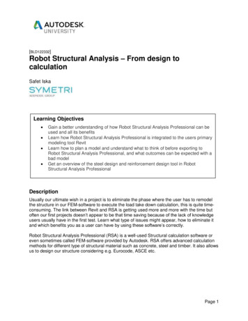
Topology Optimization MethodTopology optimization is typically used either in early stages of the design or later for reinforcement. It can also be used to findoptimal location of welds. Because topology optimization can get the stiffest structure possible, engineers quite often use topology todesign for stiffness.Topology Optimization for Preliminary DesignTopology optimization is used for preliminary design because it can give a good idea what is the load path and allows to define thebasic architecture of the car vehicle. The following example is from reference [19]. In this example 10 different load cases (withinertia relief) were used to find the optimal topology. Figure 2 shows the topology results.Fig 2 – Topology Optimization of VehicleTopology Optimization to Reinforce StructuresIf a design is completed; but if it is desirable to increase a particular performance target without adding too much mass, topologyoptimization can be used. Next two techniques that are useful are described:Second Layer Method – Allows locating the best locations to reinforce a car body that was already designed [20].Fig 3 - Topology Optimization of Vehicle. Red Areas Show Optimal Areas to ReinforceAutorib Method – Ribs are effective ways to add stiffness to certain components. This method allows to create ribs around areas ofinterest and then designed with topology [10]
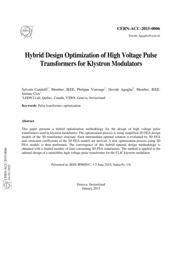
Sizing Optimization MethodSizing optimization can be used to find the optimal thickness distribution on a property by property basis. Typical problems canminimize mass subject to stress, natural frequencies and displacements constraints.Sizing Optimization for Torsional Stiffness MaximizationIn this example, sizing optimization was used to find the optimal thickness distribution to reinforce a car body. The car model has245,344 shell elements designing 51 PSHELL data entries. The objective function of the problem consists of maximizing the torsionstiffness of the car. There are 51 design variables. The study allows the thickness to grow and/or to reduce a certain percentage. Asimple case was studied where the mass was allowed to increase 2%.Figure 4 shows the thickness distribution using 6 views. Red represents the largest thickness, blue represents the smaller thickness.Fig 4 – Thickness Distribution using Sizing OptimizationResultsThe torsional stiffness was increased from 7369Nm/deg to 10,350Nm/deg giving a 40% gain. The mass increased from 288.5 kg to294.2 a 1.99% increase.
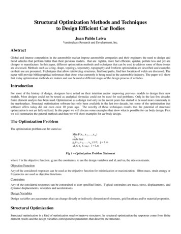
Topometry Optimization MethodTopometry optimization can be used to find the optimal thickness distribution on element by element basis. Typical problems can bemaximizing static or dynamic stiffness subject to mass and displacements constraints.Topometry Optimization for Torsional Stiffness MaximizationIn this example, topometry optimization was used to find the optimal thickness distribution to reinforce a car body. The car model has245,344 shell elements designing 51 PSHELL data entries. The objective function of the problem consists of maximizing the torsionstiffness of the car. In this case due to symmetry 122,756 design variables were used. The study allows the thickness to grown up tp 1mm to study best places to reinforce. A mass constraint allowed to it by increase 2%.Figure 5 shows the thickness distribution using 6 views. Red represents the largest thickness, blue represent the smaller thickness.Fig 5 –Optimal Places to Reinforce a Car Body using Topometry OptimizationResultsThe torsional stiffness was increased from 7369Nm/deg to 11,474Nm/deg giving a 56% gain. The mass increased from 288.5 kg to293.4 a 1.7% increase.
Freeform Optimization MethodFreeform optimization can be used to find the optimal location of bead pattern. In car bodies it allows to increase the stiffness of thevehicle without adding too much mass.Freeform Optimization for Torsional Stiffness maximizationIn this example, freeform optimization was used to find the best places to add beads to increase the torsional stiffness of the car body.The car model has 228,883 grids. The objective function of the problem consists of maximizing the torsion stiffness of the car. Thestudy allowed only 1% of the grids to move so that a reduced and more practical number of beads is actually created. A massconstraint allowed to it by increase 2%. In this case due to symmetry 127,669 design variables were used to design the grid location.The design variables correspond, in this case, to scale factors of perturbation that are normal to the surface of the car body. Figure 6shows the perturbation as small arrows. Reference [21] presented the idea used in this example for topography optimization.Fig 6 –Perturbation Vectors that Define the Design SpaceFigure 7 shows the bead pattern in colors. Red represents the largest height of the bead, blue represents no movement of grids.Fig 7– Freeform Optimization Results Shows the Optimal Place to ad Bead PatternResultsThe torsional stiffness was increased from 7369Nm/deg to 11,663Nm/deg giving a 58% gain. The mass increased from 288.5 kg to289.2 which represent a 0.2% increase.
Comparison of Different Optimization TypesWe solved the same problem using different techniques to study what kind of gain we can get by using them. The following chartshows the results for several cases studied:Fig 8 – Results of Stiffness Optimization using Different Structural Optimization TypesFigure 9 shows the type of gain versus torsion stiffness:Stiffness vs Optimization Type81Fig 9 – Results of Stiffness Optimization using Different Structural Optimization TypesFigure 9 shows that, using structural optimization, the torsional stiffness of a car body can be greatly increased without adding toomuch mass. This was observed for all types of optimizations and especially for freeform. It should be noted that this Figure is notintended for comparing the methods against each other as the used mass was not necessarily the same in each case. Reference [12]provides a case study that compares the effectiveness of topology, sizing, topometry and shape using same mass on a simple structure.
Figure 10 shows the results and the number of design variables of the studies problems:Fig 10 – Results of Stiffness Optimization using Different Structural Optimization TypesTopography Optimization MethodTopography optimization is typically used in early stages of the design. It is typically used to find optimal locations of bead patternsthat allow reinforcing panel that are not so stiffen enough like automobile hoods. Topography optimization can also be used in floorpanel, trunk and parts that are not visible.Topography Optimization for Reinforcement of Car HoodFigure 11 shows the results of topography optimization. In the picture bellow red indicates the maximum height of the beadsgenerated by optimization, blue means that grids are not moved. Green indicates lesser movements.Fig 11 – Bead Pattern Results using Topography OptimizationPublications Describing Car Bodies DesignReferences [23-32] provide additional examples of car body designs. They can be helpful to understand the usage of structuraloptimization in industry.
Spot Weld Optimization of Car Body Using Sizing OptimizationThis problem is presented in Ref. 22 so here we just give the key features of the problem. The requirements of the problem were tofind a trade-off table for the optimal locations of spot welds. The objective function of each case was to maximize the sum of the firstbending and first torsional frequencies. The constraint of the problem was the number of welds to keep. The problem was solved usingsizing optimization with 4316 design variables. The variables designed 4316 CVECTOR elements that modeled spot-welds. Thisproblem was optimized six times to study the effect of taking out different numbers of welds. Table 3 shows the results for alloptimization cases and the case where all welds were used (100%). This table gives the designer trade-off information that helps tostudy the influence of the number of welds on the rigidity of the car body.Table 3. Relation Between Rigidity and Number of WeldsQuantityof keptwelds (%)First torsionalfrequency(Hz)First bendingfrequency(Hz)Sum of twofrequencies .2598031.76210031.96245.71877.48046.18578.147Sum of 1st torsion & bending frequency(Hz)85.080.075.070.065.060.0Optimzation res ultsFully welded res ntage of welds (%)Fig 12 – Parentage of Weld versus FrequenciesFig 13 – Optimal Weld Location, 70% Kept Welds and 30% Discarded
ConclusionsSeveral methods to perform structural optimization have been presented. The use of these methods allows designers to find efficientand innovative designs which can not be achieved by traditional manual methods. The paper showed that using structuraloptimization, the stiffness of a car body can be greatly increased without adding too much mass. The methods presented allow thedesigner to explore a larger design space and improve the usage of material and/or minimize mass.AcknowledgmentsMs. Helene Bresset and Mr. Brice Mallein, from IFMA and former interns of VR&D, provided invaluable help creating some of themodels and runs presented .16.17.18.19.20.21.22.23.24.25.26.Schmit, L. A., and Farshi, B., “Some Approximation Concepts for Structural Synthesis,” AIAA J., Vol. 12(5), 1974, pp 692-699.Schmit, L. A., and Miura, H., “Approximation Concepts for Efficient Structural Synthesis,” NASA CR-2552, March 1976.Canfield, R. A., “High Quality Approximations of Eigenvalues in Structural Optimization of Trusses,” AIAA J.,Vol 28, No. 6,1990, pp. 1116-1122.Vanderplaats, G.N., “Numerical Optimization Techniques for Engineering Design: With Applications”, 2007.Vanderplaats, G.N., and Salajegheh, E., “New Approximation Method for Stress Constraints in Structural Synthesis,” AIAA J.,Vol. 27, No. 3, 1989, pp. 352-358.Vanderplaats, G.N., “Structural Design Optimization Status and Direction,” Journal of Aircraft, Vol. 36, No. 1, 1999, pp. 11-20.Vanderplaats, G.N., “Very Large Scale Optimization”, presented at the 8th AIAA/USAF/NASA/ISSMO Symposium atMultidisciplinary Analysis and Optimization, Long Beach, CA September 6-8, 2000.BIGDOT User's Manual, Version 2.0, VR&D, Colorado Springs, CO, October 2003.DOT, Design Optimization Tools User’s Manual, Version 5.0. Vanderplaats Research and Development, Colorado Springs, CO,January 1999.GENESIS User's Manual, Version 12.0 Vanderplaats Research & Development Inc., Colorado Springs, CO, December 2010.Leiva, J. P., Watson, B. C., and Kosaka, I., “Modern Structural Optimization Concepts Applied to Topology Optimization,”Proceedings of the 40th AIAA/ASME/ASCE/AHS/ASC Structures, Structural Dynamics, and Material Conference. St. Louis,MO, April 12-15, 1999, pp. 1589-1596.Leiva, J. P., “Topometry Optimization: A New Capability to Perform Element by Element Sizing Optimization of Structures”,presented at the 10th AIAA/ISSMO Symposium on Multidisciplinary Analysis and Optimization, Albany, NY, August 30 September 1, 2004.Leiva, J. P., and Watson, B. C., “Shape Optimization in the Genesis Program,” Optimization in Industry II, Banff, Canada, Jun 610, 1999.Leiva, J. P., and Watson, B. C., “Automatic Generation of Basis Vectors for Shape Optimization in the Genesis Program,” 7thAIAA/USAF/NASA/ ISSMO Symposium on Multidisciplinary Analysis and Optimization, St. Louis, MO, Sep 2-4, 1998, pp.1115-1122.Leiva, J. P., “Methods for Generation Perturbation Vectors for Topography Optimization of Structrures” 5th World Congress ofStructural and Multidisciplinary Analysis and Optimization, Lido di Jesolo, Italy, May 19-23, 2003.Leiva, J. P. , “Freeform Optimization: A New Capability to Perform Grid by Grid Shape Optimization of Structures,” 6th ChinaJapan-Korea Joint Symposium on Optimization of Structural and Mechanical Systems, Kyoto, Japan, June 22-25, 2010.Environmental Case Study Automobile, World Steel Association.Vanderplaats, G. N., “Saving Energy Through Design Optimization,” SAE Journal of Passenger Cars – Electric and ElectricalSystems, Sept. 2004, Paper No. 2003-01-1331.Quinn, G., “Full Automobile Topology Design Optimized to Maximize Structural Stiffness Subject to Multiple Static Load CasesIncluding Inertia Relief’”. 13th AIAA/ISSMO Symposium on Multidisciplinary Analysis and Optimization, Fort Worth, TX,September 13-15, 2010.Leiva, J. P., Wang, L., Recek S. and Watson, B., “Automobile Design Using the GENESIS Structural Optimization Program”,Nafems Seminar: Advances in Optimization Technologies for Product Design, Chicago, Ilinois, USA, October 22-23, 2001.Chakravarty, R., “Case Study of Topography Optimization on Automotive Body Structure”, SAE paper 2009-01-1233.Wang, L., Leiva, J. P., and Basu, P. K., “Design Optimization of Automobile Welds,” Int. J. of Vehicle Design, Vol 31, No. 4,2003,pp. 377-391.Laxman, S., Iyengar, R. M., Powers, J., and Morgans, S., “Achieving Light-Weight Design of Automotive Bodies with AdvancedStrength Steels via Structural Optimization” ,SAE paper 2009-01-0795.Laxman, S., and Iyengar, R. M., “Structural Optimization: Achieving a Robust and Light-Weight Design of AutomotiveComponents” ,SAE paper 2008-01-0869.Laxman, S., Iyengar, R. M., Morgans, S., and Koganti, R., “Harnessing Structural Optimization Techniques for DevelopingEfficient Light-Weight Vehicles” ”, SAE paper 2009-01-1234.Lee, Y. E., Sreedhar, S., Marla, D., and Pawlicki, C., “Automotive Axle Simulation and Correlation”, SAE paper 2006-01-1255.
27. Xu, S., “Use of Topology Design Exploration and Parametric Shape Optimization Process to Develop Highly Efficient andLightweight Vehicle Body Structure”.28. Lake, K., Thomas, R., Gambling, M., and Lawson, T., “The Application of FEA in the Optimization of Die Cast Components &the Consequent Reduction in Development Costs & Time”.29. Rastogi, N., “Stress Analysis and Lay-Up Optimization of an All-Composite Pick-Up Truck Chassis Structure”, SAE paper 200401-1519.30. Salway, D. and Butler, L., “Development of Composite Laminate Optimization Techniques Using Topometry Optimization inGenesis”.31. Gambling, M. and Gardner, S., “A Comparison of Vanderplaats R&D’s New STRDOT and DSCDOT Optimizers Against ItsBIGDOT Optimizer in the Application of Formula 1 Monocoque Design”.32. Gambling, M., “Efficient Topology, Topometry, and Sizing Optimization for LS-DYNA Analysis Problems”.
Design variables are parameters that can change directly or indirectly dimension of elements, grid locations and/or material properties. Structural Optimization Structural optimization is a kind of optimization used to improve structures. In struct