Transcription
CERN-ACC-2015-0006Davide.Aguglia@cern.chHybrid Design Optimization of High Voltage PulseTransformers for Klystron ModulatorsSylvain Candolfi1, Member, IEEE, Philippe Viarouge1, Davide Aguglia2, Member, IEEE,Jérôme Cros11LEEPCI Lab, Québec, Canada, 2CERN, Geneva, SwitzerlandKeywords: Pulse transformer, optimizationThis paper presents a hybrid optimization methodology for the design of high voltage pulsetransformers used in klystron modulators. The optimization process is using simplified 2D FEA designmodels of the 3D transformer structure. Each intermediate optimal solution is evaluated by 3D FEAand correction coefficients of the 2D FEA models are derived. A new optimization process using 2DFEA models is then performed. The convergence of this hybrid optimal design methodology isobtained with a limited number of time consuming 3D FEA simulations. The method is applied to theoptimal design of a monolithic high voltage pulse transformer for the CLIC klystron ented at: IEEE IPMHVC, 1-5 June 2014, Santa Fe, USGeneva, SwitzerlandJanuary,2015
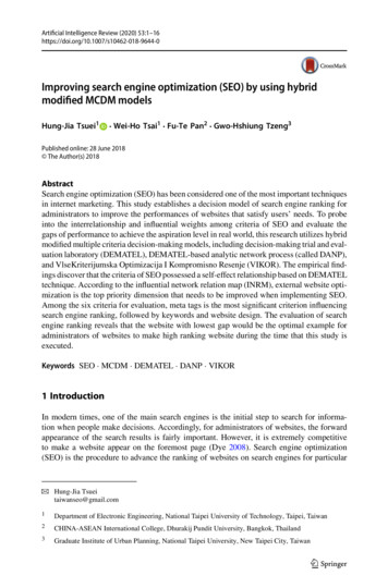
Hybrid Design Optimization of High Voltage PulseTransformers for Klystron ModulatorsSylvain Candolfi1, Member, IEEE, Philippe Viarouge1,Davide Aguglia2, Member, IEEE, Jérôme Cros11LEEPCI Lab., Electrical and Computer Eng. Dept., Laval University, G1V 0A6 Quebec (QC), CanadaEmails: sylvain.candolfi.1@ulaval.ca, philippe.viarouge@gel.ulaval.ca, jerome.cros@gel.ulaval.ca2CERN - European Organization for Nuclear Research, Technology Dept., Electric Power Converter GroupCH-1211 Geneva 23, Switzerland Email: davide.aguglia@cern.ch1 INTRODUCTIONA monolithic pulse transformer based topology is presentlyunder study at CERN for the future CLIC solid state klystronmodulators [1]. The tight pulse specifications defined inFigure 1 and listed in Table 1 require a high efficient controlof the pulse transformer performances during the designprocess.The transformer design methodology needs optimizationtechniques to maximize performance objectives in terms ofweight and volume while respecting the constraints. Such adesign approach needs magnetic and electrical dimensioningmodels to derive the transformer equivalent electrical circuitparameters with adequate sensitivity to the design parametersvariations and sufficient accuracy in order to guarantee anefficient convergence of the optimization process.It has been demonstrated in [1] that the electrical equivalentcircuit parameters used to compute the objective andconstraints functions can be directly derived with betteraccuracy from a 2D FEA dimensioning model instead of usinga simplified analytical dimensioning model.But the validation of the final optimal solution by 3D FEAsimulation of the real transformer structure obtained with the2D FEA methodology presented in [1] often shows that somespecification constraints are not precisely verified. ThisVoltage [V]This paper presents a hybrid optimization methodologyfor the design of high voltage pulse transformers used inklystron modulators. The optimization process is usingsimplified 2D FEA design models of the 3D transformerstructure. Each intermediate optimal solution is evaluatedby 3D FEA and correction coefficients of the 2D FEAmodels are derived. A new optimization process using 2DFEA models is then performed. The convergence of thishybrid optimal design methodology is obtained with alimited number of time consuming 3D FEA simulations.The method is applied to the optimal design of amonolithic high voltage pulse transformer for the CLICklystron modulator.Index Terms — Pulse transformer, optimizationlimitation is mainly related to the 2D approximation of the 3Dtransformer structure.VknVoltage [V]ABSTRACTOvershootOvershoot Droop 0.45% VnVntrisetsettptpTTreprepTimeTime[s][s]Figure 1: Definition of the specified pulse parametersTable 1: Specifications of CLIC monolithic pulse transformerValueUnitTransformer and voltage pulsespecificationsPeak output power Pp29MWPrimary nominal voltage V1n15kVSecondary nominal voltage V2n180kVPulse length tp140µsSettling time tset 8µsVoltage pulse overshoot 1 %Pulse repetition rate50HzTransformer Material specificationsInsulating material breakdown field Emax10MV/mRelative permittivity of insulating3materialRelative permeability of core magnetic4000materialSaturation flux density of core magneticT1.15material BmaxConstraints on Transformer Performance and SizeCopper losses 3 % of PpMax. overall dimensions1 x 0.5 x 1.2mOn the other hand, heavy time consuming 3D FEAsimulations are usually not applicable during the iterativeoptimization process in the case of 3D devices like themonolithic transformer structure used in modulators. In thispaper, a new hybrid optimization methodology is proposed to
solve this problem: the optimization process is always usingsimplified 2D FEA design models of the 3D transformerstructure but each intermediate optimal solution is evaluatedby 3D FEA simulation. Correction coefficients are derived andanother optimization process using corrected 2D FEA modelsis performed. With this method, the convergence of the hybridoptimal design process is obtained with a limited number oftime consuming 3D FEA simulations.2PULSE TRANSFORMER DESIGNOPTIMIZATION2.1 DESIGN VARIABLESBecause the magnetic and insulating materialcharacteristics, the voltage ratio and the pulse parameters areimposed by the specifications, the state variables of thetransformer design optimization problem can be reduced to thecore width ec, the primary winding turn number n1 and the coilheight bb (Fig.2). The maximum current density in thewindings is fixed by the thermal and efficiency constraints.The core axial length l is then imposed by the fixed materialand pulse parameters according to:CorelecC’12Ls/2C’11R1LmR2Ls/2C’22Uk a.i2/3Figure 3: Equivalent circuit of the pulse transformer with its klystron load.The parameters of the equivalent circuit are directlyidentified by 2D FEA identification tests based onmagnetostatic and electrostatic field computations accordingto the procedure already detailed by the authors in [1]. Threeelectrostatic identification tests are required for thedetermination of the capacitances: test 1 with primarysupplied at rated voltage V1n, and secondary short circuited &grounded, test 2 with secondary supplied at rated voltage V2nand primary short circuited & grounded, test 3 with primarysupplied at V1n, and secondary supplied at V2n. Thecapacitances are computed from the three total electricalenergy values derived from the electrostatic FEA simulations.Two magnetostatic identification tests are required for thedetermination of the inductances: test 1 at no-load operationwith opened secondary, test 2 under short-circuit operation atrated current. The inductances are computed from the totalmagnetic energy value derived from each magnetostatic FEAsimulation. The symbols and definitions of these energyvalues are listed in Table 2.Table 2. Nomenclature of the energy symbols of equivalent circuit FEAidentification tests: 2D model, 2D corrected with Cg, and 3DPrimary coilsSecondary coilsbbFigure 2: 3D pulse transformer structure2.2 ELECTRICAL EQUIVALENT CIRCUITIDENTIFICATIONThe equivalent electrical circuit defined in IEEE standard(Fig.3) is used to compute the output voltage pulse imposed tothe klystron. A specific klystron parameter a defines its nonlinear voltage-current characteristic Uk(ik) according to:FEA IdentificationTestsElectrostatic test 1Electrostatic test 2Electrostatic test 3Magnetostatic test 1Magnetostatic test 22D modelComputedon length lWel12DWel22DWel32DWmag12DWmag22D2D modelCorrectedwith CgWel12DcgWel22DcgWel32DcgWmag12DcgWmag22Dcg3D FEAmodelWel13DWel23DWel33DWmag13DWmag23DAccording to the two-dimensional finite element modellingassumption, the energy of each 2D FEA test can be onlycomputed on a fixed axial length of the transformer structurein the third dimension. In order to take into account thetransformer end-winding region, the energy values are firstcomputed from the 2D FEA solver for an axial length equal tol and then corrected by a geometrical factor Cg. With such anapproach, each energy value is not measured on the length ofthe transformer but on a virtual length that includes the lengthand the core width ec:According to the symbols of Table 2, the corrected energyvalues used to identify the equivalent circuit parameters are:
2.3 OPTIMIZATION METHODOLOGYAn efficient Generalized Reduced Gradient (GRG2)algorithm is used to perform the transformer designoptimization. The objective function to minimize is thetransformer volume and the non-linear constraints functionsare built from the transformer and voltage pulse specificationslisted in Table 1. For each iteration of the optimizationprocedure, the objective and constraint functions are derivedfrom the three state variables ec, n1 and bb by the 2D FEAidentification procedures, followed by the simulation of theelectrical equivalent circuit of Fig.3. Such a design approachhas been successfully applied by the authors in [1], with thelimits of the two-dimensional finite element modellingassumption that is using a geometrical correction factor Cg. Itis now interesting to evaluate the sensitivity of the optimaldesign to the limitation of the 2D approximation by 3D FEAsimulation.methodology proposed in the next paragraph is taking thisconclusion into account.4The basic optimization methodology using 2D FEAidentification procedures with the geometrical correctionfactor Cg described in paragraph 2.3 can be associated to anerror compensation mechanism illustrated by the flowchart ofFig.6. For each intermediate optimal design solution, onecompares the five energy values given by the 2D FEA to thoseobtained by a 3D FEA simulation and corrected by Cg. If thereis a difference between these two sets of parameters, thissolution is not acceptable. One must apply five specificcorrection factors to the 2D FEA results to improve itsaccuracy.Wmag12DWmag12D(a)lel1lel2ecec(b)Figure 5: Electrical field distribution in a horizontal half cross section of thetransformer, (a) Electrostatic test 1, (b) Electrostatic test 2Moreover, in the case of the short-circuit test related to theidentification of the total transformer leakage inductance, theenergy differences are higher even with use of the basicgeometrical correction factor Cg. One can conclude from thiscomparative analysis that different correction factors must beadopted to compute the stored energy in each identificationtest. The correction mechanism of the hybrid optimizationWmag13DWmag13DEnergy [-]Wmag22DWmag22D5321Wel12DWel12D0.30.4Core length [m]0.5Wel12DcgWel12DcgWel13DWel13D32320.30.4Core length [m]0.5Wel22DcgWel22DcgWel23DWel23D0.30.4Core length 10.2Wel32DWel32D0.30.4Core length [m]0.5Wel32DcgWel32DcgWel33DWel33D0.215Energy [-]4Wmag23DWmag23D40.2Energy [-]4Wmag22DcgWmag22Dcg10.2Energy [-]To investigate the influence of the two-dimensional finiteelement modelling assumption on the transformercharacteristics, several 3D FEA simulations of the fiveidentification tests have been performed for a transformer witha fixed cross section and a variable axial core length l in thethird dimension. For each identification test, the three differentestimations of the total electrical (or magnetic energy) areplotted in Fig.4 according to the terminology of the energysymbols listed in Table 2. When the core length l goes toinfinity, the energy values computed by 2D and 3D FEAconverge because the contribution of the transformer endwinding region is becoming negligible. One can notice fromthe five energy-core length characteristics that the ratiobetween the energy values obtained by 2D and 3D FEA arenot identical for each identification test. Fig. 5 presents theelectrical field distribution in a horizontal half transformercross section. One can verify that the average length of theinter-winding space where the most important amount ofelectrical energy is stored is different from one test to theother.Energy [-]COMPARISON OF 2D AND 3D FEAMODELLINGEnergy [-]43HYBRID DESIGN 4Core length [m]0.50.20.61.01.4Core length [m]1.8Figure 4: Energy-core length characteristics derived from 2D FEA, 2D FEAwith geometrical correction factor Cg and 3D FEA for the 5 identification testsAccording to the terminology of the energy symbols listed inTable 2, these correction factors are computed from:The corrected energy values used to compute the equivalentcircuit parameters are then:Another optimization process using 2D FEA identificationprocedures with these corrected energy values is then initiated.The correction factors are initialized to 1 for the firstintermediate optimization step. After each intermediateoptimization step, a 3D FEA simulation is performed.
200Evaluation of performanceswith the 3D FEA modelOptimization with the corrected2D FEA modelConstraintssatisfied?Convergence ofthe optimum?1202D FEA methodologyhybrid methodology8040NoCorrection with the 3D model 5 corrections factorsdeduced0051015Time [µs]YesFigure 7: Output voltage pulse rise time and settling time obtained with thebasic optimization methodology using 2D FEA and the hybrid designmethodologyFinal solutionFigure 6: Flowchart of the hybrid design optimization method using a 3DFEA correction mechanism.The correction factors are then computed. The final optimalsolution is obtained when both set of parameters are identical.5160Voltage [kV]Optimization with 2D FEAmodelStartInitialization of the variablesCorrection factors 1HYBRID DESIGN OPTIMIZATIONEXAMPLEThe hybrid optimization methodology has been applied tothe design of the monolithic pulse transformer for the CLICklystron modulator with the specifications listed on Table 1.The objective function to minimize was the transformervolume. Three intermediate optimization steps are sufficient tominimize the 2D FEA model errors and to validate the finaloptimal solution. The main transformer dimensions and theoutput voltage pulse settling time are listed (in Bold) in Table3. The optimal result of the basic optimization methodologyusing 2D FEA identification procedures with the geometricalcorrection factor Cg and no 3D FEA correction is alsopresented and normalized to the hybrid optimization solution.The output voltage pulse rise time and settling time obtainedwith the basic optimization methodology using 2D FEA andthe hybrid design optimization methodology are presented onFig.7.6CONCLUSIONThis study shows that it is possible to compensate theinfluence of the two-dimensional finite element modellingerrors due to the contribution of the transformer end-windingregion in the third dimension with a limited number of timeconsuming 3D FEA simulations by using a hybridoptimization methodology. The overall convergence of theprocess is very fast and the 3D FEA software always validatesthe optimal solution. The convergence of this method isverified in the case of the optimal design of a monolithic highvoltage pulse transformer for the CLIC klystron modulator.REFERENCES[1][2][3][4]S. Candolfi, P. Viarouge, D. Aguglia, J. Cros, "Finite element basedoptimal design approach for high voltage pulse transformers", PulsedPower Conference (PPC), 2013 19th IEEE, vol., no., pp.1,6, 16-21 June2013P. Viarouge, D. Aguglia, C. A. Martins, J. Cros, "Modeling anddimensioning of High Voltage pulse transformers for klystronmodulators", Electrical Machines (ICEM), 2012 XXth InternationalConference on , vol., no., pp.2332,2338, 2-5 Sept. 2012L.S. Lasdon, A.D. Waren, A. Jain and M. Ratner, “Design and testing ofa generalized reduced gradient code for nonlinear programming”, ACMTransaction on Matheatical Software, Vol. 4, No.1, pp.34-49.G.N. Glasoe, J.V.L, Pulse Generators, New York: Dover Publications,Inc., 1965Table 1: Optimization results with basic 2D FEA optimization and hybrid optimization methods for CLIC specifications.Optimization methodologyBasic 2D FEA optimizationHybrid g time 3DCore widthFEA model [µs]9.6 µs93%100%8.0 µsec 0.094mCoil height[%]92%100%bb 0.453mNumber of turns[%]97%100%n1 36
: Pulse transformer, optimization . Abstract . This paper presents a hybrid optimization methodology for the design of high voltage pulse transformers used in klystron modulators. The optimization process is using simplified 2D FEA design models of the 3D transformer structure.