Transcription
DESIGN OFMASONRY STRUCTURESThird edition of Load Bearing Brickwork DesignA.W.Hendry, B.Sc., Ph.D., D.Sc, F.I.C.E., F.I. Struct.E., F.R.S.E.B.P.Sinha, B.Sc., Ph.D., F.I. Struct.E., F.I.C.E., C. Eng.andS.R.Davies, B.Sc., Ph.D., M.I.C.E., C.Eng.Department of Civil EngineeringUniversity of Edinburgh, UKE & FN SPONAn Imprint of Chapman & HallLondon · Weinheim · New York · Tokyo · Melbourne · Madras 2004 Taylor & Francis
Published by E & FN Spon, an imprint of Chapman & Hall, 2–6Boundary Row, London SE1 8HN, UKChapman & Hall, 2–6 Boundary Row, London SE1 8HN, UKChapman & Hall GmbH, Pappelallee 3, 69469 Weinheim, GermanyChapman & Hall USA, 115 Fifth Avenue, New York, NY 10003, USAChapman & Hall Japan, ITP-Japan, Kyowa Building, 3F, 2–2–1Hirakawacho, Chiyoda-ku, Tokyo 102, JapanChapman & Hall Australia, 102 Dodds Street, South Melbourne,Victoria 3205, AustraliaChapman & Hall India, R.Seshadri, 32 Second Main Road, CITEast, Madras 600 035, IndiaThis edition published in the Taylor & Francis e-Library, 2004.First edition 1997 1997 A.W.Hendry, B.P.Sinha and S.R.DaviesFirst published as Load Bearing Brickwork Design(First edition 1981. Second edition 1986)ISBN 0-203-36240-3 Master e-book ISBNISBN 0-203-37498-3 (Adobe eReader Format)ISBN 0 419 21560 3 (Print Edition)Apart from any fair dealing for the purposes of research or private study,or criticism or review, as permitted under the UK Copyright Designs andPatents Act, 1988, this publication may not be reproduced, stored, ortransmitted, in any form or by any means, without the prior permission inwriting of the publishers, or in the case of reprographic reproduction only inaccordance with the terms of the licences issued by the Copyright LicensingAgency in the UK, or in accordance with the terms of licences issued bythe appropriate Reproduction Rights Organization outside the UK. Enquiriesconcerning reproduction outside the terms stated here should be sent tothe publishers at the London address printed on this page.The publisher makes no representation, express or implied, with regard tothe accuracy of the information contained in this book and cannot acceptany legal responsibility or liability for any errors or omissions that may bemade.A catalogue record for this book is available from the British Library 2004 Taylor & Francis
ContentsPreface to the third editionPreface to the second editionPreface to the first editionAcknowledgements1Loadbearing masonry buildings1.1Advantages and development of loadbearingmasonry1.2Basic design considerations1.3Structural safety: limit state design1.4Foundations1.5Reinforced and prestressed masonry2Bricks, blocks and mortars2.1Introduction2.2Bricks and blocks2.3Mortar2.4Lime: non-hydraulic or semi-hydraulic lime2.5Sand2.6Water2.7Plasticized Portland cement mortar2.8Use of pigments2.9Frost inhibitors2.10Proportioning and strength2.11Choice of unit and mortar 2004 Taylor & Francis
2.122.132.14Wall tiesConcrete infill and groutReinforcing and prestressing steel3 Masonry properties3.1General3.2Compressive strength3.3Strength of masonry in combined compressionand shear3.4The tensile strength of masonry3.5Stress-strain properties of masonry3.6Effects of workmanship on masonry strength4 Codes of practice for structural masonry4.1Codes of practice: general4.2The basis and structure of BS 5628: Part 14.3BS 5628: Part 2—reinforcedand prestressed masonry4.4Description of Eurocode 6 Part 1–1(ENV 1996–1–1:1995)5 Design for compressive loading5.1Introduction5.2Wall and column behaviour under axial load5.3Wall and column behaviour under eccentric load5.4Slenderness ratio5.5Calculation of eccentricity5.6Vertical load resistance5.7Vertical loading5.8Modification factors5.9Examples6 Design for wind loading6.1Introduction6.2Overall stability6.3Theoretical methods for wind load analysis6.4Load distribution between unsymmetricallyarranged shear walls7 Lateral load analysis of masonry panels7.1General7.2Analysis of panels with precompression7.3Approximate theory for lateral load analysis of wallssubjected to precompression with and without returns 2004 Taylor & Francis
7.47.5Effect of very high precompressionLateral load design of panels withoutprecompression8Composite action between walls and other elements8.1Composite wall-beams8.2Interaction between wall panels and frames9Design for accidental damage9.1Introduction9.2Accidental loading9.3Likelihood of occurrence of progressive collapse9.4Possible methods of design9.5Use of ties10Reinforced masonry10.1Introduction10.2Flexural strength10.3Shear strength of reinforced masonry10.4Deflection of reinforced masonry beams10.5Reinforced masonry columns, using BS 5628: Part 210.6Reinforced masonry columns, using ENV 1996–1–111Prestressed masonry11.1Introduction11.2Methods of prestressing11.3Basic theory11.4A general flexural theory11.5Shear stress11.6Deflections11.7Loss of prestress12 Design calculations for a seven-storey dormitory buildingaccording to BS 562812.1Introduction12.2Basis of design: loadings12.3Quality control: partial safety factors12.4Calculation of vertical loading on walls12.5Wind loading12.6Design load12.7Design calculation according to EC6 Part 1–1(ENV 1996–1:1995)12.8Design of panel for lateral loading:BS 5628 (limit state)12.9Design for accidental damage 2004 Taylor & Francis
12.10Appendix: a typical design calculationfor interior-span solid slab13 Movements in masonry buildings13.1General13.2Causes of movement in buildings13.3Horizontal movements in masonry walls13.4Vertical movements in masonry wallsNotationBS 5628EC6 (where different from BS 5628)Definition of terms used in masonryReferences and further reading 2004 Taylor & Francis
Preface to the third editionThe first edition of this book was published in 1981 as Load BearingBrickwork Design, and dealt with the design of unreinforced structuralbrickwork in accordance with BS 5628: Part 1. Following publication ofPart 2 of this Code in 1985, the text was revised and extended to coverreinforced and prestressed brickwork, and the second edition publishedin 1987.The coverage of the book has been further extended to includeblockwork as well as brickwork, and a chapter dealing with movementsin masonry structures has been added. Thus the title of this third editionhas been changed to reflect this expanded coverage. The text has beenupdated to take account of amendments to Part 1 of the British Code,reissued in 1992, and to provide an introduction to the forthcomingEurocode 6 Part 1–1, published in 1996 as ENV 1996–1–1. This documenthas been issued for voluntary use prior to the publication of EC6 as aEuropean Standard. It includes a number of ‘boxed’ values, which areindicative: actual values to be used in the various countries are to beprescribed in a National Application Document accompanying the ENV.Edinburgh, June 1996 2004 Taylor & Francis
Preface to the second editionPart 2 of BS 5628 was published in 1985 and relates to reinforced andprestressed masonry which is now finding wider application in practice.Coverage of the second edition of this book has therefore been extendedto include consideration of the principles and application of this form ofconstruction.Edinburgh, April 1987 2004 Taylor & Francis
Preface to the first editionThe structural use of brick masonry has to some extent been hamperedby its long history as a craft based material and some years ago itsdisappearance as a structural material was being predicted. The fact thatthis has not happened is a result of the inherent advantages of brickworkand the design of brick masonry structures has shown steadydevelopment, based on the results of continuing research in manycountries. Nevertheless, structural brickwork is not used as widely as itcould be and one reason for this lies in the fact that design in thismedium is not taught in many engineering schools alongside steel andconcrete. To help to improve this situation, the authors have written thisbook especially for students in university and polytechnic courses instructural engineering and for young graduates preparing forprofessional examination in structural design.The text attempts to explain the basic principles of brickwork design,the essential properties of the materials used, the design of various structuralelements and the procedure in carrying out the design of a completebuilding. In practice, the basic data and methodology for structural designin a given material is contained in a code of practice and in illustratingdesign procedures it is necessary to relate these to a particular documentof this kind. In the present case the standard referred to, and discussed insome detail, is the British BS 5628 Part 1, which was first published in 1978.This code is based on limit state principles which have been familiar tomany designers through their application to reinforced concrete designbut which are summarised in the text.No attempt has been made in this introductory book to give extensivelists of references but a short list of material for further study is includedwhich will permit the reader to follow up any particular topic in greaterdepth.Preparation of this book has been based on a study of the work of alarge number of research workers and practising engineers to whom the 2004 Taylor & Francis
authors acknowledge their indebtedness. In particular, they wish toexpress their thanks to the following for permission to reproducematerial from their publications, as identified in the text: BritishStandards Institution; Institution of Civil Engineers; the BuildingResearch Establishment; Structural Clay Products Ltd.Edinburgh, June 1981 2004 Taylor & FrancisA.W.HendryB.P.SinhaS.R.Davies
AcknowledgementsPreparation of this book has been based on a study of the work of a largenumber of research workers and practising engineers, to whom theauthors acknowledge their indebtedness. In particular, they wish toexpress thanks to the British Standards Institution, the Institution of CivilEngineers, the Building Research Establishment and Structural ClayProducts Ltd for their permission to reproduce material from theirpublications, as identified in the text. They are also indebted to the BrickDevelopment Association for permission to use the illustration of CavernWalks, Liverpool, for the front cover.Extracts from DD ENV 1996–1–1:1995 are reproduced with thepermission of BSI. Complete copies can be obtained by post from BSICustomer Services, 389 Chiswick High Road, London W4 4AL. Usersshould be aware that DD ENV 1996–1–1:1995 is a prestandard; additionalinformation may be available in the national foreword in due course. 2004 Taylor & Francis
1Loadbearing masonry buildings1.1ADVANTAGES AND DEVELOPMENT OF LOADBEARINGMASONRYThe basic advantage of masonry construction is that it is possible to usethe same element to perform a variety of functions, which in asteelframed building, for example, have to be provided for separately,with consequent complication in detailed construction. Thus masonrymay, simultaneously, provide structure, subdivision of space, thermaland acoustic insulation as well as fire and weather protection. As amaterial, it is relatively cheap but durable and produces external wallfinishes of very acceptable appearance. Masonry construction is flexiblein terms of building layout and can be constructed without very largecapital expenditure on the part of the builder.In the first half of the present century brick construction for multistorey buildings was very largely displaced by steel- andreinforcedconcrete-framed structures, although these were very oftenclad in brick. One of the main reasons for this was that until around 1950loadbearing walls were proportioned by purely empirical rules, whichled to excessively thick walls that were wasteful of space and materialand took a great deal of time to build. The situation changed in a numberof countries after 1950 with the introduction of structural codes ofpractice which made it possible to calculate the necessary wall thicknessand masonry strengths on a more rational basis. These codes of practicewere based on research programmes and building experience, and,although initially limited in scope, provided a sufficient basis for thedesign of buildings of up to thirty storeys. A considerable amount ofresearch and practical experience over the past 20 years has led to theimprovement and refinement of the various structural codes. As a result,the structural design of masonry buildings is approaching a level similarto that applying to steel and concrete. 2004 Taylor & Francis
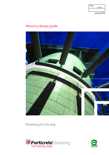
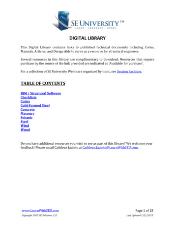
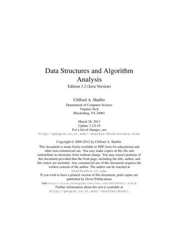
1.2BASIC DESIGN CONSIDERATIONSLoadbearing construction is most appropriately used for buildings inwhich the floor area is subdivided into a relatively large number ofrooms of small to medium size and in which the floor plan is repeated oneach storey throughout the height of the building. These considerationsgive ample opportunity for disposing loadbearing walls, which arecontinuous from foundation to roof level and, because of the moderatefloor spans, are not called upon to carry unduly heavy concentrations ofvertical load. The types of buildings which are compatible with theserequirements include flats, hostels, hotels and other residentialbuildings.The form and wall layout for a particular building will evolve fromfunctional requirements and site conditions and will call forcollaboration between engineer and architect. The arrangement chosenwill not usually be critical from the structural point of view providedthat a reasonable balance is allowed between walls oriented in theprincipal directions of the building so as to permit the development ofadequate resistance to lateral forces in both of these directions. Veryunsymmetrical arrangements should be avoided as these will give rise totorsional effects under lateral loading which will be difficult to calculateand which may produce undesirable stress distributions.Stair wells, lift shafts and service ducts play an important part indeciding layout and are often of primary importance in providing lateralrigidity.The great variety of possible wall arrangements in a masonry buildingmakes it rather difficult to define distinct types of structure, but a roughclassification might be made as follows: Cellular wall systems Simple or double cross-wall systems Complex arrangements.A cellular arrangement is one in which both internal and external wallsare loadbearing and in which these walls form a cellular pattern in plan.Figure 1.1 (a) shows an example of such a wall layout.The second category includes simple cross-wall structures in whichthe main bearing walls are at right angles to the longitudinal axis of thebuilding. The floor slabs span between the main cross-walls, andlongitudinal stability is achieved by means of corridor walls, as shown inFig. 1.1(b). This type of structure is suitable for a hostel or hotel buildinghaving a large number of identical rooms. The outer walls may be clad innon-loadbearing masonry or with other materials.It will be observed that there is a limit to the depth of building whichcan be constructed on the cross-wall principle if the rooms are to have 2004 Taylor & Francis
Fig. 1.1 Typical wall arrangements in masonry buildings. 2004 Taylor & Francis
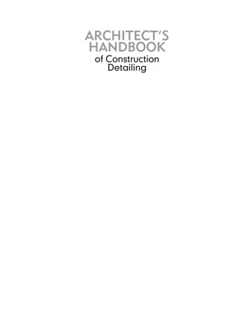
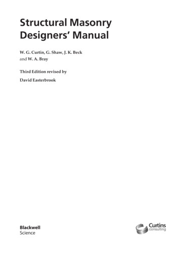
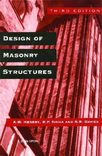
effective day-lighting. If a deeper block with a service core is required, asomewhat more complex system of cross-walls set parallel to both majoraxes of the building may be used, as in Fig. 1.1(c).All kinds of hybrids between cellular and cross-wall arrangements arepossible, and these are included under the heading ‘complex’, a typicalexample being shown in Fig. 1.1(d).Considerable attention has been devoted in recent years to thenecessity for ensuring the ‘robustness’ of buildings. This has arisen froma number of building failures in which, although the individualmembers have been adequate in terms of resisting their normal serviceloads, the building as a whole has still suffered severe damage fromabnormal loading, resulting for example from a gas explosion or fromvehicle impact. It is impossible to quantify loads of this kind, and what isrequired is to construct buildings in such a way that an incident of thiscategory does not result in catastrophic collapse, out of proportion to theinitial forces. Meeting this requirement begins with the selection of walllayout since some arrangements are inherently more resistant toabnormal forces than others. This point is illustrated in Fig. 1.2: abuilding consisting only of floor slabs and cross-walls (Fig. 1.2(a)) isobviously unstable and liable to collapse under the influence of smalllateral forces acting parallel to its longer axis. This particular weaknesscould be removed by incorporating a lift shaft or stair well to provideresistance in the weak direction, as in Fig. 1.2(b). However, the flank orgable walls are still vulnerable, for example to vehicle impact, andlimited damage to this wall on the lowermost storey would result in thecollapse of a large section of the building.A building having a wall layout as in Fig. 1.2(c) on the other hand isclearly much more resistant to all kinds of disturbing forces, having ahigh degree of lateral stability, and is unlikely to suffer extensive damagefrom failure of any particular wall.Robustness is not, however, purely a matter of wall layout. Thus afloor system consisting of unconnected precast planks will be much lessresistant to damage than one which has cast-in-situ concrete floors withtwo-way reinforcement. Similarly, the detailing of elements and theirconnections is of great importance. For example, adequate bearing ofbeams and slabs on walls is essential in a gravity structure to preventpossible failure not only from local over-stressing but also from relativemovement between walls and other elements. Such movement couldresult from foundation settlement, thermal or moisture movements. Anextreme case occurs in seismic areas where positive tying together ofwalls and floors is essential.The above discussion relates to multi-storey, loadbearing masonrybuildings, but similar considerations apply to low-rise buildings wherethere is the same requirement for essentially robust construction. 2004 Taylor & Francis
Fig. 1.2 Liability of a simple cross-wall structure to accidental damage. 2004 Taylor & Francis
1.3STRUCTURAL SAFETY: LIMIT STATE DESIGNThe objective of ensuring a fundamentally stable or robust building, asdiscussed in section 1.2, is an aspect of structural safety. The measuresadopted in pursuit of this objective are to a large extent qualitative andconceptual whereas the method of ensuring satisfactory structuralperformance in resisting service loads is dealt with in a morequantitative manner, essentially by trying to relate estimates of theseloads with estimates of material strength and rigidity.The basic aim of structural design is to ensure that a structure shouldfulfil its intended function throughout its lifetime without excessivedeflection, cracking or collapse. The engineer is expected to meet thisaim with due regard to economy and durability. It is recognized,however, that it is not possible to design structures which will meet theserequirements in all conceivable circumstances, at least within the limitsof financial feasibility. For example, it is not expected that normallydesigned structures will be capable of resisting conceivable butimprobable accidents which would result in catastrophic damage, suchas impact of a large aircraft. It is, on the other hand, accepted that there isuncertainty in the estimation of service loads on structures, that thestrength of construction materials is variable, and that the means ofrelating loads to strength are at best approximations. It is possible that anunfavourable combination of these circumstances could result instructural failure; design procedures should, therefore, ensure that theprobability of such a failure is acceptably small.The question then arises as to what probability of failure is ‘acceptablysmall’. Investigation of accident statistics suggests that, in the context ofbuildings, a one-in-a-million chance of failure leading to a fatality willbe, if not explicitly acceptable to the public, at least such as to give rise tolittle concern. In recent years, therefore, structural design has aimed,indirectly, to provide levels of safety consistent with a probability offailure of this order.Consideration of levels of safety in structural design is a recentdevelopment and has been applied through the concept of ‘limit state’design. The definition of a limit state is that a structure becomes unfit forits intended purpose when it reaches that particular condition. A limitstate may be one of complete failure (ultimate limit state) or it may definea condition of excessive deflection or cracking (serviceability limit state).The advantage of this approach is that it permits the definition of directcriteria for strength and serviceability taking into account theuncertainties of loading, strength and structural analysis as well asquestions such as the consequences of failure.The essential principles of limit state design may be summarized asfollows. Considering the ultimate limit state of a particular structure, for 2004 Taylor & Francis
failure to occur:(1.1)whereis the design strength of the structure, andthe design loading effects. Here m and f are partial safety factors; Rk andQk are characteristic values of resistance and load actions, generally chosensuch that 95% of samples representing Rk will exceed this value and 95%of the applied forces will be less than Qk.The probability of failure is then:(1.2)If a value of p, say 10-6, is prescribed it is possible to calculate values ofthe partial safety factors, m and f, in the limit state equation whichwould be consistent with this probability of failure. In order to do this,however, it is necessary to define the load effects and structuralresistance in statistical terms, which in practice is rarely possible. Thepartial safety factors, therefore, cannot be calculated in a precise way andhave to be determined on the basis of construction experience andlaboratory testing against a background of statistical theory. Theapplication of the limit state approach as exemplified by the British Codeof Practice BS 5628 and Eurocode 6 (EC 6) is discussed in Chapter 4.1.4FOUNDATIONSBuilding structures in loadbearing masonry are characteristically stiff inthe vertical direction and have a limited tolerance for differentialmovement of foundations. Studies of existing buildings have suggestedthat the maximum relative deflection (i.e. the ratio of deflection to thelength of the deflected part) in the walls of multi-storeyed loadbearingbrickwork buildings should not exceed 0.0003 in sand or hard clay and0.0004 in soft clay. These figures apply to walls whose length exceedsthree times their height. It has also been suggested that the maximumaverage settlement of a brickwork building should not exceed 150 mm.These figures are, however, purely indicative, and a great deal dependson the rate of settlement as well as on the characteristics of the masonry.Settlement calculations by normal soil mechanics techniques willindicate whether these limits are likely to be exceeded. Where problemshave arisen, the cause has usually been associated with particular typesof clay soils which are subject to excessive shrinkage in periods of dryweather. In these soils the foundations should be at a depth of not lessthan 1 m in order to avoid moisture fluctuations.High-rise masonry buildings are usually built on a reinforced concreteraft of about 600mm thickness. The wall system stiffens the raft and 2004 Taylor & Francis
helps to ensure uniform ground pressures, whilst the limitation on floorspans which applies to such structures has the effect of minimizing theamount of reinforcement required in the foundation slab. Underexceptionally good soil conditions it may be possible to use spreadfootings, whilst very unfavourable conditions may necessitate pilingwith ground beams.1.5REINFORCED AND PRESTRESSED MASONRYThe preceding paragraphs in this chapter have been concerned with theuse of unreinforced masonry. As masonry has relatively low strength intension, this imposes certain restrictions on its field of application.Concrete is, of course, also a brittle material but this limitation isovercome by the introduction of reinforcing steel or by prestressing. Thecorresponding use of these techniques in masonry construction is notnew but, until recently, has not been widely adopted. This was partly dueto the absence of a satisfactory code of practice, but such codes are nowavailable so that more extensive use of reinforced and prestressedmasonry may be expected in future.By the adoption of reinforced or prestressed construction the scope ofmasonry can be considerably extended. An example is the use ofprestressed masonry walls of cellular or fin construction for sports hallsand similar buildings where the requirement is for walls some 10 m inheight supporting a long span roof. Other examples include the use ofeasily constructed, reinforced masonry retaining walls and thereinforcement of laterally loaded walls to resist wind or seismic forces.In appropriate cases, reinforced masonry will have the advantage overconcrete construction of eliminating expensive shuttering and ofproducing exposed walls of attractive appearance without additionalexpense.Reinforcement can be introduced in masonry elements in severalways. The most obvious is by placing bars in the bed joints or collarjoints, but the diameter of bars which can be used in this way is limited.A second possibility is to form pockets in the masonry by suitablebonding patterns or by using specially shaped units. The steel isembedded in these pockets either in mortar or in small aggregateconcrete (referred to in the USA as ‘grout’). The third method, suitable forwalls or beams, is to place the steel in the cavity formed by two leaves (orwythes) of brickwork which is subsequently filled with small aggregateconcrete. This is known as grouted cavity construction. Elements built inthis way can be used either to resist in-plane loading, as beams or shearwalls, or as walls under lateral loading. In seismic situations it is possibleto bond grouted cavity walls to floor slabs to give continuity to thestructure. Finally, reinforcement can be accommodated in hollow block 2004 Taylor & Francis
walls or piers, provided that the design of the blocks permits theformation of continuous ducts for the reinforcing bars.Prestressed masonry elements are usually post-tensioned, the steel, instrand or bar form, being accommodated in ducts formed in themasonry. In some examples of cellular or diaphragm wall constructionthe prestressing steel has been placed in the cavity between the twomasonry skins, suitably protected against corrosion. It is also possible toprestress circular tanks with circumferential wires protected by an outerskin of brickwork built after prestressing has been carried out. 2004 Taylor & Francis
2Bricks, blocks and mortars2.1INTRODUCTIONMasonry is a well proven building material possessing excellentproperties in terms of appearance, durability and cost in comparisonwith alternatives. However, the quality of the masonry in a buildingdepends on the materials used, and hence all masonry materials mustconform to certain minimum standards. The basic components ofmasonry are block, brick and mortar, the latter being in itself a compositeof cement, lime and sand and sometimes of other constituents. The objectof this chapter is to describe the properties of the various materialsmaking up the masonry.2.22.2.1BRICKS AND BLOCKSClassificationBrick is defined as a masonry unit with dimensions (mm) not exceeding337.5 225 112.5 (L w t). Any unit with a dimension that exceeds anyone of those specified above is termed a block. Blocks and bricks aremade of fired clay, calcium silicate or concrete. These must conform torelevant national standards, for example in the United Kingdom to BS3921 (clay units), BS 187 (calcium silicate) and BS 6073: Part 1 (concreteunits). In these standards two classes of bricks are identified, namelycommon and facing; BS 3921 identifies a third category, engineering: Common bricks are suitable for general building work. Facing bricks are used for exterior and interior walls and available in avariety of textures and colours. Engineering bricks are dense and strong with defined limits ofabsorption and compressive strength as given in Table 2.2. 2004 Taylor & Francis
Bricks must be free from deep and extensive cracks, from damage toedges and corners and also from expansive particles of lime.Bricks are also classified according to their resistance to frost and themaximum soluble salt content.(a) Designation according to frost resistance Frost resistant (F): These bricks are durable in extreme conditions ofexposure to water and freezing and thawing. These bricks can be usedin all building situations. Moderately frost resistant (M): These bricks are durable in the normalcondition of exposure except in a saturated condition and subjected torepeated freezing and thawing. Not frost resistant (O): These bricks are suitable for internal use. Theyare liable to be damaged by freezing and thawing unless protected byan impermeable cladding during construction and afterwards.(b) Designation according to maximum soluble salt content Low (L): These clay bricks must conform to the limit prescribed by BS3921 for maximum soluble salt content given in Table 2.1. Allengineering and some facing or common bricks may come under thiscategory. Normal (N): There is no special requirement or limit for soluble saltcontent.2.2.2VarietiesBricks may be wire cut, with or without perforations, or pressed withsingle or double frogs or cellular. Perforated bricks contain holes; thecross-sectional area of any one hole should
structural engineering and for young graduates preparing for professional examination in structural design. The text attempts to explain the basic principles of brickwork design, the essential properties of the materials used, the design of various structural elements and the procedure in carryin