Transcription
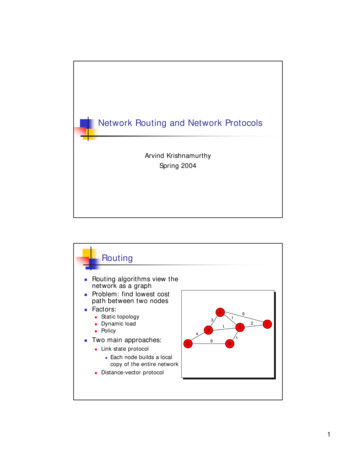
Proceedings of the International Association for Shell and Spatial Structures (IASS) Symposium 2010, ShanghaiSpatial Structures – Permanent and TemporaryNovember 8-12 2010, Shanghai, ChinaValidating Thrust Network Analysis using 3D-printed,structural modelsPhilippe BLOCK1*, Lorenz LACHAUER2, Matthias RIPPMANN21*Assistant Professor, Institute of Technology in Architecture, ETH ZurichWolfgang-Pauli-Strasse 15, HIL E 46.18093 Zurich, SWITZERLANDblock@arch.ethz.ch2Research Assistant, Institute of Technology in Architecture, ETH ZurichAbstractScale models can be used to understand the equilibrium of masonry systems –and structural compression forms in general– as they stand not because of allowablestresses, but because of their geometry. This paper demonstrates the use of 3D-printed,structural models, and emphasizes their relevance, not only to assess the stability ofcomplex masonry vaults, but also to push the limits of new compression-only structures.Thrust Network Analysis (TNA) is an innovative approach for exploring threedimensional funicular networks [1]. The TNA methodology was originally developedfor stability analysis of historic vaulted structures in unreinforced masonry, extendinggraphic statics to fully 3-D problems. This framework is even more powerful as flexibleapproach for finding structural compression forms. Through the control of reciprocalforce diagrams, which relate form and forces, new unexpected forms for compressiononly shells become possible.This paper will show and discuss some surprising compression forms obtained withTNA to demonstrate how the approach gives the designer the power to start exploitingstructurally indeterminacy of three-dimensional funicular systems. Thanks to recentadvances in TNA [2], which integrate the interactive structural form finding processwith geometric and fabrication constraints into a smooth digital chain, discrete 3Dprinted scale models can easily be produced. These unglued “masonry” scale modelsserve as very convincing first validations of the capabilities of this novel approach.Keywords: Structural scale models, form finding, rapid prototyping, masonry vaults, funicular vs.freeform design1 IntroductionGothic cathedrals were built well before the introduction of structural theory [3]. Theold master builders counted on experience and exceptional intuition –but also a lot oftrial and error– to accomplish their stunning vaulted spaces in unreinforced masonry.They were furthermore also helped by a specific property of masonry structures. Unlikemodern structures, not stress, but stability is of concern for this type of structures [4,5].Because masonry has no (or very little) capacity to resist the induced tension due tobending, it has to be shaped such that it acts in compression only. If an unreinforced
Proceedings of the International Association for Shell and Spatial Structures (IASS) Symposium 2010, ShanghaiSpatial Structures – Permanent and TemporaryNovember 8-12 2010, Shanghai, Chinamasonry structure does not have a good structural form, it will collapse. “Masonry doesnot lie”, and the stability of masonry structures is thus mainly a question of geometry,and not of material failure. In general, the stresses are low in structures which follow theflow of compressive forces, i.e. funicular structures, particularly when they are as bulkyas most historic structures in masonry.That the behaviour of masonry structures is only a matter of geometry, and not ofstresses, makes their behaviour independent of scale. This powerful notion made itpossible for the master builders to push the limits of imagination over centuries ofevolution of form. They could use geometric rules (Fig. 1), which allowed them to copythe geometry of successful precedents and to scale them up; and scale models, whichallowed them to check the stability of vaulted creations and to carefully balance themwhere necessary by adding blocks on the extrados.Fig. 1: Geometrical rules for stable arch-on-buttresses structures, and drawings ofdisplacement studies with plaster models [6].The stability of masonry structures is best assessed with limit analysis [3,7]. Simply put,an unreinforced masonry structure will be stable if within its section a compression-onlysystem of forces can be found in equilibrium with the applied loads [8,9]. The appliedloads are for masonry structures their dominant self weight. In order to be able to applyan equilibrium analysis (i.e. limit analysis) for the safety assessment of masonrystructures, Heyman introduced three key assumptions [10]: masonry has no tensilecapacity, sliding does not occur at the interfaces of the separate voussoirs (blocks), andmasonry is considered rigid. These will be discussed further in the paper.2 Learning from the old master buildersThe understanding of the equilibrium of complex vaulted structures in masonry hasbeen lost over the centuries. One is dazzled when realizing that the stunning fan vaultsof the chapel of King’s College at the University of Cambridge, England have astructural stone shell with an average thickness–over-span ratio smaller than that of an
Proceedings of the International Association for Shell and Spatial Structures (IASS) Symposium 2010, ShanghaiSpatial Structures – Permanent and TemporaryNovember 8-12 2010, Shanghai, Chinaegg shell. This becomes even more impressive when understanding that this structure iscomposed of thin stone slats held in place only by compression (and friction).Thrust Network Analysis (TNA), a fully three-dimensional equilibrium approach,allows now to explain and visualize their stability by finding compression-onlynetworks of forces, staying within the geometry of the structures [9]. Originallydeveloped for the analysis of masonry vaults, this approach becomes more powerful asdesign tool. TNA allows the designer to carefully control three-dimensional funicular,i.e. compression-only, shapes. This flexible control results in a new formal language forstone structures.The goal of this paper is to demonstrate the power of TNA for the design of novelshapes in unreinforced stone, and thus shells in general, which attempts to blur theboundaries between funicular and freeform design. A first, but convincing validation forthis approach is given by discrete, unglued structural models with surprising shapes.3 From abstract to modelAn important challenge in realizing the structural models presented in this paper, is thetransition from the abstract and discrete representation used for form finding, to thephysical parts of the model. An example of a similar challenge is the translation of thehanging string model for the crypt of the Colonia Güell Church into an actual stonestructure. It is Antoni Gaudí who was able to see form through these strings.Using TNA, a thrust network is generated, comparable to the strings in Gaudí’s hangingmodel. In the form-finding process, several levels of control are provided (Fig. 3): formdiagram, force diagram and loading ( self-weight) density. The form diagram definesthe general outline of the structure, and force line topology, and the force diagramrepresents the equilibrium of the inner forces in the form diagram, or the horizontalforce components of the resulting thrust network. Both diagrams enable the directcontrol by the user on form and the force distribution of the thrust network. The nodalself weight applied for the form finding process is controlled by the user as well.By linking a continuous geometric representation, a NURBS surface, to the thrustnetwork, tessellation and block generation independent from the given primal grid, ispossible. Thanks to these recent developments in TNA [2], efficient design andproduction of the structural models presented in this paper became possible.The structural behaviour of these unglued models is similar to the behaviour ofunreinforced masonry vaults, because of the satisfactory fulfilment of Heyman’s threenecessary requirements, i.e. the three assumptions introduced in Section 1:- No tension: The compression-only geometry, generated by TNA, prevents tensionforces to occurunder the (dominant) design loading.- Rigid: The materials used for the 3D printed have very stiff material propertiescompared to the forces in the models. The funicular form, as a result of theformfinding using TNA, furthermore results in very low stresses, resulting in verysmall strains. The voussoirs can thus be considered as rigid.- No sliding: Two conditions want to be satisfied to prevent this: the interfaces needto have “enough” friction (i.e. more than the Coulomb friction, or a friction angle of0.6 or higher), and the stereotomy of the vault (i.e. how the vault volume is cut into
Proceedings of the International Association for Shell and Spatial Structures (IASS) Symposium 2010, ShanghaiSpatial Structures – Permanent and TemporaryNovember 8-12 2010, Shanghai, Chinablocks) has to be such that sliding failure mechanism are prevented. The latter canbe guaranteed by controlling the tessellation and individual block geometries. Toprovide sufficient friction between the model parts, the choice of rapid prototypingtechnique is crucial. Plaster-based 3D printers produce fairly rough pieces that haveenough friction, which makes this technique perfect for the purpose of structuraltesting. A disadvantage of these printers is that geometrical tolerances seem not thatreliable due to inaccuracies from e.g. shrinking. Further research is being done tocontrol this process. Other rapid prototyping technologies are Fused DepositionModelling (FDM) and Specific Laser Sintering (SLS), which are highly accurate interms of geometry, but the surfaces of the thermoplastic material are very smoothand provide almost no friction. In order to prevent the interfaces to slide, small noninterlocking notches are provided at the interfaces of the voussoirs (Fig. 2). Thesewere also helpful in the accurate registration of the pieces, controlling andsimplifying assembly.Fig. 2: Notches to avoid local sliding failure at the interfaces.4 Designing a free-from masonry vaultIn this section, the design process for a freeform, masonry-like vault model will bedescribed. Using commercial NURBS modelling software, two input surfaces were builtwith one common edge, and two tangential edges. Using their local coordinate system,the form diagram, or primal grid, representing the choice of force lines in the vault andthus also the topology or planar projection of the thrust network was generated (Fig.3a). From this, the reciprocal force diagram, or dual grid, is produced (Fig. 3b). Thelengths of the branches in the dual grid represent the horizontal force components in thebranches of the thrust network. Due to the structural indeterminacy of the primal grid, itis possible to deform the dual grid while maintaining certain rules [1]. An overlay of theinformation of primal and dual grid is the force distribution, represented by the pipe
Proceedings of the International Association for Shell and Spatial Structures (IASS) Symposium 2010, ShanghaiSpatial Structures – Permanent and TemporaryNovember 8-12 2010, Shanghai, Chinadiagram in Figure 3c. The radii of the pipes are proportional to the axial forces in thebranches. For a chosen self weight distribution, the thrust network is generated (Fig.3d). The force distribution diagram (Fig. 3c) allows for a good interpretation of theresulting form of the thrust network, but also clarifies and visualizes that internal forcesin the shell have to be redistributed in a certain way in order to achieve a specific threedimensional effect. The thickest pipe segments on top of the diagram e.g. represent theforces in the most shallow edge arch (Fig. 6); the “loose ends” on the right side of thediagram represent the one continuously supported edge; or the backbone-like segmentsin the middle show the stepwise accumulation of forces in that region. Thisaccumulation or channelling of forces results in the accretive kink in the thrust networktowards the support.Figure 6 shows some local changes of the tessellation in detail, in order to preventsliding mechanisms, e.g. the geometry of the edge pieces (highlighted in blue) areconstrained to but cut perpendicular to the edge arches.Fig. 3: The TNA form finding process of a “freeform” vault: a) the form diagram,generated from two “stitched” NURBS surfaces; b) its corresponding reciprocal forcediagram; c) a pipe diagram, visualizing the force distribution; and d) the resultingcompression-only thrust network in equilibrium with a given loading.
Proceedings of the International Association for Shell and Spatial Structures (IASS) Symposium 2010, ShanghaiSpatial Structures – Permanent and TemporaryNovember 8-12 2010, Shanghai, ChinaFig. 4: Perspective view of the vault model.Fig. 5: Perspective view of the vault model.Fig. 6: Front view of the vault model.
Proceedings of the International Association for Shell and Spatial Structures (IASS) Symposium 2010, ShanghaiSpatial Structures – Permanent and TemporaryNovember 8-12 2010, Shanghai, ChinaFig. 7: Top view of the vault model with marked edge tessellation pattern.Fig. 8: Support details, showing the unglued pieces held together by compression.
Proceedings of the International Association for Shell and Spatial Structures (IASS) Symposium 2010, ShanghaiSpatial Structures – Permanent and TemporaryNovember 8-12 2010, Shanghai, China5 Structural models as analysis toolsThe current paper only showed the successful, first results of the capabilities of TNA byproducing stable scale models of unreinforced masonry shells with novel shapes. Thiscan be considered as a first validation of the approach.More importantly, as the drawings of the tests with plaster models by Danyzy (Fig. 1,[6]) showed for two-dimensional structures, scale models can be used to investigate thestability and collapse mechanisms of discrete structures under e.g. supportdisplacements or concentrated live loads (Fig. 9). This is a really hard, and not at allunderstood, problem for complex three-dimensional vaulted structures.The use of scale models for sophisticated, three-dimensional structures, both historicand new, is now possible thanks to improved rapid prototyping technologies. The use of3D printed scale models to further the understanding of collapse mechanism in 3Dmasonry has been first introduced by the first author, together with Prof. JohnOchsendorf at MIT [13]. This approach has provided new insides into the stability ofmasonry domes [14,15]. Beyond the structural arguments for scale models, [2] givesadditional reasons how scale models are invaluable design tools for new structures inmasonry.Fig. 9: Collapse sequence of a masonry vault model under point loads.
Proceedings of the International Association for Shell and Spatial Structures (IASS) Symposium 2010, ShanghaiSpatial Structures – Permanent and TemporaryNovember 8-12 2010, Shanghai, China6 ConclusionsThis paper showed new directions for masonry design possible thanks to newextensions to TNA. Rapid prototyping technology, combined with a customized digitalworkflow for the planning and production, has been successfully used to efficientlybuild structural masonry-like models. These models allow for a first validation and newinsights in structural behaviour of such novel vault forms. Furthermore, due to thescalability of compression-only structures, they enable a reliable prediction of thebehaviour of a real scale stone structure for corresponding load assumptions.This paper demonstrated a prototypical case study for the design, production, andbehaviour of 3d-printed models of masonry structures. Next research steps include thesetup of a testing laboratory at the ETH Zurich, that will enable a systematic testing andanalysis of masonry structures based on structural models.7 AcknowledgmentsThe authors would like to thank Stefan Kindschi for his help with building and takingpictures of the models.References[1] Block P and Ochsendorf J. Thrust Network Analysis: A new methodology forthree-dimensional equilibrium. Journal of the International Association for Shelland Spatial Structures, 2007; 48: 167-173.[2] Lachauer L, Rippmann M and Block P. Form Finding to Fabrication: A digitaldesign process for masonry vaults. Proceedings of the International Association forShell and Spatial Structures (IASS) Symposium 2010, Shanghai, China.[3] Addis B. Building: 3,000 Years of Design, Engineering and Construction.London/NYC, Phaidon Press, 2007.[4] Huerta S. Mechanics of masonry vaults: The equilibrium approach. In P. B.Lourenço and P. Roca (Eds.) Proceedings of Historical Constructions 2001.Guimaraes, 47-69.[5] Huerta S. Arcos bovedas y cupulas. Geometria y equilibrio en el calculo tradicionalde estructuras de fabrica. Madrid, Instituto Juan de Herrera, 2004.[6] Heyman J. The Stone Skeleton: Structural engineering of masonry architecture.Cambridge, Cambridge University Press, 1995.[7] Danyzy A. Méthode générale pour déterminer la résistance qu'il faut opposer à lapoussée des voûtes. Histoire de la Société des Sciences établie à Montpellier 1732;2: 40-56.[8] Block P, Ciblac T and Ochsendorf J. Real-time limit analysis of vaulted masonrybuildings. Computers and Structures 2006; 84(29-30): 1841-1852.[9] Heyman J. The stone skeleton. International Journal of Solids and Structures 1966;2: 249-279.
Proceedings of the International Association for Shell and Spatial Structures (IASS) Symposium 2010, ShanghaiSpatial Structures – Permanent and TemporaryNovember 8-12 2010, Shanghai, China[10] Block P. Thrust Network Analysis: Exploring Three-dimensional Equilibrium. PhDDissertation. Massachusetts Institute of Technology. Cambridge, 2009.[11] Chilton J. Finding Heinz Isler – The Engineer’s Contribution to ContemporaryArchitecture, Thomas Telford Ltd., 2000.[12] Addis B. A history of using scale models to inform the design of structures. In S.Huerta (Ed.) Essays in the history of the theory of structures. In honour of JacquesHeyman 2005. Madrid, Instituto Juan de Herrera, 9-44.[13] Block P. “Equilibrium y’all” Blog: http://equilibriumstone.wordpress.com/[14] Zessin J, Lau W and Ochsendorf J. Equilibrium of cracked masonry domes, ICEEngineering and Computational Mechanics 2010.[15] Quinonez A, Zessin J and Ochsendorf J. Small-Scale Models for the Analysis ofMasonry Structures. Proceedings of the 7th International Conference on StructuralAnalysis of Historical Constructions - SAHC 2010. Shanghai, China.
branches. For a chosen self weight distribution, the thrust network is generated (Fig. 3d). The force distribution diagram (Fig. 3c) allows for a good interpretation of the resulting form of the thrust networ