Transcription
How to Build a Printed CircuitBoard1Advanced Circuits Inc 2004
This presentation is a work in progress. Asmethods and processes change it will beupdated accordingly. It is intended only as anintroduction to the production processes used inbuilding a circuit board and as a training aid foremployees, customers and friends of AdvancedCircuits. Many of the process descriptions usedhere are very generic in nature. Some depictspecific processes used by Advanced Circuitsand may not reflect practices used by othermanufacturers.2Advanced Circuits Inc 2004
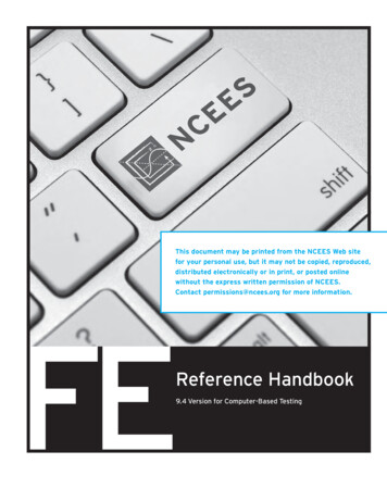
Single & Double Sided CircuitBoardsA single sided board is made fromrigid laminate consisting of awoven glass epoxy basematerial clad with copper on oneside of varying thickness.Double sided boards are madefrom the same type of basematerial clad with copper on twosides of varying thickness.Copper FoilLaminate3Advanced Circuits Inc 2004
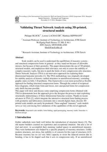
Multi-Layer BoardMulti-layer boards are madefrom the same base materialwith copper foil on the top &bottom and one or more“inner layer”cores. Thenumber of “layers”corresponds to the numberof copper foil layers.Inner Layer CoreCopper FoilLaminateCopper Foil4Advanced Circuits Inc 2004
Multi-Layer Board FabricationMulti-layer fabrication begins withthe selection of an inner layercore –or thin laminate materialof the proper thickness. Corescan vary from 0.038”to 0.005”thick and the number of coresused will depend upon theboard’s design.Copper FoilLaminate5Advanced Circuits Inc 2004
Dry-film Resist CoatingInner Layer Core MaterialA light sensitive film or photoimage-able “resist”is thenapplied by heat and pressure tothe metal surfaces of the core.The film is sensitive toultraviolet light. You will find“yellow light”used in mostImage processing areas toprevent inadvertent exposure ofthe resist. The filters remove thewave length of light that wouldaffect the resist coating.Resist Coating6Advanced Circuits Inc 2004
Photo Tools or ArtworkThe gerber data or electronic data for the part is usedto plot film that depicts the traces and pads of theboard’s design. The photo tools or artwork includesolder mask and legend or nomenclature as well asthe copper features. This film is used to place animage on the resist.7Advanced Circuits Inc 2004
Internal Signal LayerInternal Ground LayerExternal Signal LayerEach of the circuit and land patterns are unique to thatpart number and each layer has its own artwork patternor piece of film. Inner layer film is negative and outerlayer film is positive.8Advanced Circuits Inc 2004
Inner layer film is“negative”. That meansthat the copper patternsleft behind afterprocessing the core arethe “clear”areas on thefilm.Outer layer film is“positive”. The tracesand pads that are“opaque”on the film arecopper on the outside ofthe board and the clearareas will be clear ofcopper.9Advanced Circuits Inc 2004
Image ExposePanels are then exposed to a high intensity ultravioletlight source coming through the film. Clear areasallow light to pass through and polymerize (harden)the film resist thus creating an image of the circuitpattern –similar to a negative and a photograph.FilmResist10Advanced Circuits Inc 2004
Image DevelopThe exposed core is processedthrough a chemical solutionor developer that removesthe resist from areas thatwere not polymerized by thelight.Exposed CopperResist11Advanced Circuits Inc 2004
Inner Layer EtchThen the copper is chemically removed from thecore in all areas not covered by the dry-filmresist. This creates the copper pattern thatmatches the film pattern.The core laminatesurface is exposed in areas where copper wasetched away.12Advanced Circuits Inc 2004
Resist StripAfter etch, the developed dry-filmresist is chemically removedfrom the panel leaving thecopper on the panel. Traces,pads, ground plane and otherdesign features are nowexposed.13Advanced Circuits Inc 2004
Automated Optical Inspectionor AOIInner layers are then inspectedagainst design rules usingdata from the gerber files.If allowed and practical, somerepairs can be made at thispoint. Information on defectsis shared with theappropriate departments tocorrect any processproblems.14Advanced Circuits Inc 2004
Oxide CoatingAfter inspection the panels arechemically treated to improveadhesion of the copper surface.Advanced Circuits uses organicchemistry that leaves the coppera dark brown. Other types ofchemistry or mechanicalmethods can be used and colorsvary widely.15Advanced Circuits Inc 2004
Multi-Layer ConstructionThe basic materials needed to builda multi-layer board are copperfoil, prepreg and ced Circuits Inc 2004
Copper FoilThe copper foil used in circuit boards is typically in sheetsof ½ oz. and 1 oz. per square foot in weight or 0.0007and 0.00134 inches nominal thickness. In other words one ounce of copper will cover one square foot when itis rolled out to a thickness of 0.00134”or 1.34 mils.1 oz. 1 square foot1.34 mils thick17Advanced Circuits Inc 2004
PrePreg orPreimpregnated Bonding SheetIt’s the “glue”that holds the cores together. There are manytypes of materials, we use FR4 –a woven fiberglass cloth preimpregnated with epoxy resin - known in the industry as Bstage.The resin is activated and “melts”during the lamination processfrom pressure and heat. It flows across copper features andexposed laminate on the core and as it cools bonds the layersof foil and core together.18Advanced Circuits Inc 2004
Laminated PanelsInner layer core, copper foil and prepreg are bondedtogether under heat and pressure, sometimes in avacuum, during the lamination process. The resultis a panel with several layers of copper inside aswell as the foil on the outside.PrepregFoilCore19Advanced Circuits Inc 2004
Theproduction process for bothmulti-layer and double sidedpanels is generally the sameafter lamination of the multilayer panels.20Advanced Circuits Inc 2004
Primary or First DrillHoles of various sizes are drilled through a stack of panels(usually 2 to 3 high). The locations are determined bythe board’s designer to fit specific components. Drilledhole sizes are usually 5 mils larger than finished platedthrough hole sizes to allow for the copper platingprocess.Layer 1 foilPrepregLayers 2 & 3 on a CorePrepregDrilled HoleLayer 4 foil21Advanced Circuits Inc 2004
DeburrDeburr is an abrasive mechanical process thatremoves the raised edges of the metal or burrssurrounding the holes that occur during the drillingprocess. Any debris that may be left in the holes isalso removed at this time.22Advanced Circuits Inc 2004
Desmear Multi-layer Boards OnlyDesmear generally appliesonly to multilayer boards.It is a chemical process thatremoves the thin coating ofresin from the inner layerconnections that isproduced by the heat andmotion of the drill bits asthey create the holes.Removing the resin smearimproves the electricalconnectivity.Desmear Areas23Advanced Circuits Inc 2004
Electroless CopperDepositionOnce the smear is removed, a thin coating of copper ischemically deposited on all of the exposed surfaces ofthe panel, including the hole walls. This creates ametallic base for electroplating copper into the holesand onto the surface. The thickness of the electrolessdeposit is between 45 & 60 millionths of an inch.24Advanced Circuits Inc 2004
Dry-film Resist CoatingOuter Layer PanelsThe same resist or lightsensitive film used on theinner layers is used for theouter layers. The filmcovers the entire surfaceincluding the drilled holes.Resist Coating25Advanced Circuits Inc 2004
Outer Layer Expose & DevelopAfter dry film lamination the panel is exposed and developedusing the same procedure used for the inner layer cores.Clear areas in the film allow light to pass through andharden the resist creating an image of the circuit pattern Allof the drilled holes that are exposed will be plated through.Copper exposedafter developExposed Hole26Advanced Circuits Inc 2004
Copper “Pattern”PlateThe electroplating processes that electrically platescopper onto the exposed metal surfaces is next. Thecopper will be plated up to a thickness of approximately1 mil (0.001”), depending on the required final finish forthe panel.Copper Platedonto theexposedsurface andinto the holes27Advanced Circuits Inc 2004
Tin PlatingThe copper plating step is followed by plating tinonto all the exposed copper surfaces. The tin willbe used as an etch resist to maintain the coppertraces, hole pads and walls during the outer layeretch process.Tin Platedover theCopper28Advanced Circuits Inc 2004
Resist StripThe developed dry film resist is now removed from thepanel. The tin plating is not affected. Any holes thatwere covered with resist are now open and will benon-plated. This is the first step in the commonphrase “strip-etch-strip”or “SES”process.ResistremovedexposingCopper foil.29Advanced Circuits Inc 2004
EtchCopper is now removed from all parts of the panel that are notcovered by tin. The tin resists the chemicals used to etchaway the copper. Only the pads and traces from the artworkare left behind on the panel surface. The “E”of SES.30Advanced Circuits Inc 2004
Tin StripThen the tin is chemically removed leaving behind a barecopper and laminate panel. The surface pads, traces andplated through holes are the exposed copper. This is thelast step in strip-etch-strip.31Advanced Circuits Inc 2004
Clean and Prep for SolderMaskThe exposed copper surface pads, traces and platedthrough holes must be clean and free of oxidation priorto applying solder mask. During the cleaning processthe surface is scrubbed with pumice to improveadhesion of the mask as well as to remove any surfacecontamination.32Advanced Circuits Inc 2004
LPI Solder Mask ApplicationA photo-sensitive epoxy based ink is applied, completelycoating the panel. It is then dried to the touch but not finalcured. Using a method identical to image, the panels areexposed to a light source through a film tool. Then the panelis developed exposing the copper pads and hole defined bythe artwork.33Advanced Circuits Inc 2004
Solder Mask CureSolder mask is normally cured by baking in an oven;however, some fabricators are using infrared heatsources. The primary purpose of the mask is to restrictthe areas that will be covered with solder. It also protectspanels from contamination, handling damage andpossible electrical shorting during assembly andinstallation.At Advanced Circuits, whenever possible, legend ornomenclature would be screened on the panels beforefurther processing. Also, at Advanced the nickel andgold plating for edge connectors occurs immediatelyafter final cure of the solder mask and legend.34Advanced Circuits Inc 2004
There are a number of processing options that canoccur depending upon the desired final finish. Currently atAdvanced Circuits we can provide our customers with aSnPb or lead free solder finish, hard gold, Electro lessNickel Immersion Gold (ENIG), immersion tin orimmersion silver. Other finishes include OrganicSolderable Preservative (OSP), soft or bondable gold anda number of other “exotic”finishes like palladium.“Normal”processing would continue with theapplication of solder.35Advanced Circuits Inc 2004
Legend, Silkscreen,Nomenclature,Component DesignatorInk is silkscreened onto one or both sides of the paneldepending on the requirements of the customer. Theprinting usually dictates component placement, partnumber or name, date code, logo or other specifiedinformation. Panels are then baked to cure the ink.36Advanced Circuits Inc 2004
Hot Air Solder Leveling (HASL)The panels are coated with flux –a viscous compound thatpromotes even coating of the copper. Then the panelsare dipped completely into a bath of molten solder. Thesolder covers all exposed metal surfaces. As the panel isremoved from the solder, high pressure hot air isdirected at both sides of the panel. The “blast”of airremoves excess solder from the holes and smoothes thesurface of the pads.37Advanced Circuits Inc 2004
Rout, Fabrication, Score, BevelAfter HASL the boards are cut to size on a CNC machine orrouter. Most panels have the individual parts routed out intosingle pieces or arrays of varying sizes. Boards or arrays canalso be scored so that they can be easily broken apart afterassembly.Scorelines38Advanced Circuits Inc 2004
Then the boards are generally checked for cleanliness,sharp edges, burrs and other fabrication requirements.Chamfers, slots, countersinks and bevels are addedduring the rout & fabrication processes.SlotChamferBevel39Advanced Circuits Inc 2004
Bare Board Electrical TestBoards are tested for opens and shorts in the circuitry, in one ofthe last steps of production. Test programs can be loadeddirectly onto various types of test machines or used to createspecific fixtures and test programs.Flying Probe testmachine.40Advanced Circuits Inc 2004
Dedicatedfixture on auniversal gridtest machine.Shorts are repaired when possible and retested forverification. At Advanced Circuits we test 100% of thenetworks on the board for continuity and isolation (opensand shorts) using test programs generated from theGerber data.41Advanced Circuits Inc 2004
Final InspectionBoards are visually inspected toassure they meet ourcustomers’requirements,industry specifications andAdvanced Circuits’standards,as well as having the physicaldimensions and hole sizesverified.42Advanced Circuits Inc 2004
Packaging and ShipCircuit boards meeting the acceptability standards arecounted, shrink wrapped and readied for shipmentalong with all the required certificates, samples, crosssections, etc. All of these are packaged for shipmentusing products made from renewable resourcematerials.43Advanced Circuits Inc 2004
The EndThis presentation is intended only as an introduction tothe processes used in building a circuit board and as atraining aid for employees, customers and friends ofAdvanced Circuits.All of the artwork, photography and text is the property ofAdvanced Circuits Inc and may not be used withoutpermission. Please Contact Tony Garramone, CorporateTraining Manager at1-800-979-4pcb x344 for information.44Advanced Circuits Inc 2004
The copper foil used in circuit boards is typically in sheets of ½ oz. and 1 oz. per square foot in weight or 0.0007 and 0.00134 inches nominal thickness. In other words - one ounce of copper will cover one square foot when it is rolled out to a thickness of 0.