Transcription
INTERNATIONAL JOURNAL OFCOASTAL & OFFSHORE ENGINEERING.IJCOE No. 1/Winter 2016 (15-23)Engineering Critical Assessment of Offshore Pipelines under OperationalLoading Phase According to BS 7910 GuidelineSeyed Mohammad Hossein Sharifi1, Mehran Kaveh2, Hamed Saeidi Googarchin31Assisstant Professor, Faculty of Marine Science, Petroleum University of Technology, Abadan, Iran;Sharifi@put.ac.ir2M.Sc Student, Faculty of Marine Science, Petroleum University of Technology, Abadan, Iran; MKaveh@put.ac.ir3Assistant Professor, School of Automotive Engineering, Iran University of Science and Technology, Tehran, Iran;HSaeidi@iust.ac.irARTICLE INFOABSTRACTArticle History:Received: 15 Nov. 2016Accepted: 15 Mar. 2016Offshore pipelines are an efficient long-distance transportation method for oiland gas. These are usually constructed by the use of girth welds, while weldsmay naturally contain flaws. Hence, it is essential to inspect the fractureresponse of girth welds in order to check the structural integrity of thepipeline. One of the guidelines that is using wide spread for investigating thefracture response of steel structures is BS 7910 which is based on EngineeringCritical Assessment (ECA) method. In this paper Engineering CriticalAssessment (ECA) of offshore pipeline girth welds is done according to BS7910 through Crackwise software and the influence of several parameters onECA is presented. It is concluded that Influence of misalignment on axialinternal surface flaws is more significant than on axial external flaws.Furthermore it is observed that internal surface flaws have always largervalues for tolerable defect heights than external surface cracks. In addition,circumferential surface flaws have evermore larger amount of acceptance levelin defect heights than axial flaws.[ DOR: 20.1001.1.25382667.2016.1.0.1.6 ][ Downloaded from ijcoe.org on 2022-04-28 ]Keywords:Engineering critical assessment(ECA)offshore pipelinesurface cracksgirth weld misalignment, BS 7910Institute (EPRI). The EPRI equations for fully plasticcondition suppose a simple power law for thematerial's plastic stress-strain curve. Anisworthmodified the EPRI relationships in order to make itmore representative of the flow behavior of realmaterials. He defined reference stress approach andsubstituted it to the plastic component of EPRIprocedure to characterize the possibility of plasticcollapse alongside fracture failure [5]. With additionalsimplifications and modifications to the referencestress approach, BS7910:2005[6] express it in termsof a Failure Assessment Diagram (FAD). At themoment, this regulation is widely used in order todetermine defect acceptance criterion in steelstructures.First attempts on ECA analysis in accordance with BS7910 code have been made by Darcis et al [7]. Theystudied fracture assessment process in fillet-weldedjoints where cracks emanate from the weld toe.Pysarsky and his colleagues [8] investigated ECAanalysis of high strength steel pipeline girth weldswhich are subjected to plastic axial loading. Severalstudies have been performed in order to comparedifferent methods of ECA analysis. Permana [9]1. IntroductionIn order to transport oil and gas e.g. from theplatforms to land-based terminals, offshore pipelinesare utilized which are usually composed of a numberof short pipes joined by welding. The girth welds maycontain weld imperfections of certain size (height andlength) at specific location along the longitudinaldirection of the weld. [1]. Therefore, it is important tofind a suitable fracture assessment procedure forwelded pipeline and know how these eventual cracksdevelop in order to assess the structural integrity ofthe pipelines [2]. For this means, two methods wereintroduced which are quality control and Fitness-ForPurpose (FFP) approaches. Quality control approachusually gives both arbitrary and conservative levelsfor acceptance; however FFP procedure make theacceptance levels very less conservative by providingthe conditions to cause failures in structures are notreached[3]. Engineering Critical Assessment (ECA) isa FFP procedure which is based on fracture mechanicsprinciples. It was introduced by Kumar et al [4] in1981. They proposed an analytical methodology forcomputing crack driving force based on J-Integralwhich was published by Electric Power Research15
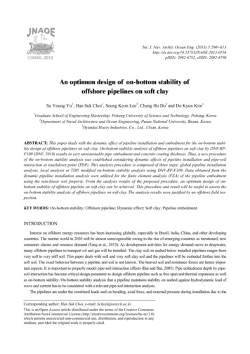
[ DOR: 20.1001.1.25382667.2016.1.0.1.6 ][ Downloaded from ijcoe.org on 2022-04-28 ]Seyed Mohammad Hossein Sharifi et. al./ Engineering Critical Assessment of Offshore Pipelines under Operational Loading Phase According to BS 7910Guidelineperformed a case study on ECA analysis of a pipelinegirth weld during reeling installation and compare BS7910 code with direct finite element. Although BS7910 tends to be conservative for long crack lengthscompared to finite element analysis, it shows lessconservative critical crack sizes in the region of shortcracks. Smith and Pisarski [10] compare API 1104Appendix A and BS 7910 FAD procedure with andwithout residual stress. Larger flaws are allowed bythe BS 7910 procedure compared with API 1104procedure, irrespective of whether the safety factor onflaw length is included or not in the API 1104assessment. Also, Larrosa and Anisworth [11] showedthe differences in ECA results which are assessed bythe API 579, the UK nuclear industry standard forfracture assessment (R6), and BS 7910 procedures.They revealed that BS 7910 has larger plastic collapselimitation compare to the other codes.However, few literatures contribute to investigate theeffect of various parameters on ECA of offshorepipelines in accordance with BS 7910. Holtman [12]focused on examining the fracture behavior ofoffshore pipeline steel in sour environment(containing water and hydrogen sulphide). Wei andHandley [13] presented the effects of bi-axialstressing (internal pressure plus external axial loading)on ECA analysis of plate and cylinder containingsurface cracks. Recently, Bonara et al [14]investigated the ECA procedure to assess CRA weldsfor clad and lined pipe material in bi-metallic girthweld joints. As an extension, this study is aimed toinvestigate the influence of axial misalignment ingirth welds and ductile tearing on engineering criticalassessment of girth welded offshore pipelines underoperational loading phase based on BS 7910 guidelinefor various flaw geometries.Standards Institution set up a logical acceptancestandard which was both safer and more economicalthan the traditional workmanship acceptancestandards.In BS 7910: 2013[3], there are three levels,available for a fracture assessment. The Level 1 whichis called simplified assessment procedure is based ona conservative Failure Assessment Diagram (FAD)applicable when the data on the materials properties islimited. The Level 1 FAD has Kr, Sr co-ordinates,where Kr is the ratio of applied crack driving force tofracture toughness and Sr the ratio of applied stress toflow strength where the flow strength is mean of yieldand tensile strength hence including some plasticity.For the cases where single-value measurements offracture toughness are available level 2 which isnamed normal assessment method is used. Furtherthere are two assessment strategies: Level 2A andLevel 2B. When material specific full stress–straininformation is available, Level 2B is utilized based onreference stress solution. Level 3 is similar as level 2with the exception that is appropriate for ductilematerials showing tearing mode of failure with Level3A and 3B dependent on the type of stress-strain dataavailable. A typical figure of level 2 FAD is shown infigure 1.In this paper, influence of various parameters onengineering critical assessment of offshore pipelines isperformed. Accordingly, a brief overview of BS7910and theoretical background of engineering criticalassessment method is provided; afterward,geometrical configurations, mechanical properties ofpipeline materials, and loading scenarios are describedin details. Influence of axial misalignment in girthwelds and ductile tearing on ECA analysis of offshorepipeline in various flawed geometries is presentedbased on BS 7910 code. Finally, summary of resultsand conclusions are given in the last section.Figure 1- BS 7910 level 2 failure assessment diagram[3]According to BS7910 level 2B, a flaw can beaccepted when the following equation is satisfied: E refL 3 Y S Kr r Y S L r 2 E ref 1/ 2(1)In the above equations, Kr KI / Kmat is fractureratio, σref is reference stress, εref is the true strainobtained from the uni-axial tensile stress-strain curveat reference stress, Lr σref /YS is load ratio andLr(max) UTS YS /2YS is cut-off value, E is theYoung’s modulus. The first term in equation 1considers both the limiting elastic and fully plasticbehaviors. The second term determines the response1.BS 7910Because workmanship standards settle totally specificrules for allowable lengths of slag inclusion anddensity of porosity, a large amount of repair work iscarried out for innocuous planar flaws such as cracksbased on these codes. It has been estimated that suchunnecessary repairs may add as much as 10% toconstruction costs [15]. In this order, British16
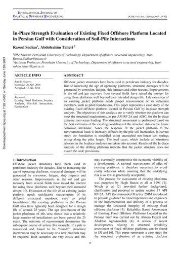
Seyed Mohammad Hossein Sharifi et. al. / IJCOE 2016, No. 1; p.15-23in between these two limits where the generalbehavior is elastic but fracture parameter exceeds itselastic value, and a minor plasticity correction issupply by this term.2.1.Geometrical ConfigurationThe outer radius of pipeline is 203.2 mm, and theaverage wall thickness is 20.4 mm. The length of thepipe is considered three times as long as the outerdiameter. Two types of cracks are proposed which areincluding external surface and internal surface flaws.These defects are located in axial and circumferentialdirection along the pipeline length and girth weld,respectively. Figure 2 shows the pipeline cross sectionalongside with various crack types used in this paper."rO" represent outer radius of the pipeline, "B" showsaverage wall thickness, the crack height is symbolizedas "a", and "2c" representing the crack length and "p"showing crack ligament height in embedded flaws.[ DOR: 20.1001.1.25382667.2016.1.0.1.6 ][ Downloaded from ijcoe.org on 2022-04-28 ]2.MethodologyIn order to perform engineering critical assessment ofoffshore pipeline in accordance with BS 7910guideline, Crackwise software [16] is utilized.Crackwise is a software which is used to computemultiple parametric equations, propagating flaws inductile tearing, calculation of limiting conditions (forexample, the maximum tolerable flaw size in astructure under given conditions), reporting, editingand archiving such complex calculations. Input valuesof this software for current study are as fallows.(a)(b)(c)(d)Figure 2- Crack geometries used in current study: (a) axial external surface, (b) axial internal surface, (c) circumferential externalsurface, (d) Circumferential internal surface flaws [16]Hence, a full stress-strain curve can be determineduniquely by the CSA equation for the input YS, UTS,and uEL. Based on the aforementioned observations,in this paper the CSA Z662 equation is selected toproduce the full stress-strain curves (option 2 inCrackwise FAD failure locus) in all models. Table 1shows the input information for generating stressstrain curve which is mentioned in reference [18].2.2.Material PropertiesTwo stress-strain curve equations which are widelyused for modeling engineering materials are RambergOsgood equation and the CSA Z662 [17] equation.CSA Z662 in contrast to Ramberg-Osgood equationprovides the relationship between the stress and strainas mentioned in equation 2: E (0.005 YS n)( )E YSn ln ((2)where E is young modules, YS is the yield stress at0.5% strain and n is the strain hardening exponent ofthe CSA equation. Equation 3 determines a unique nfor any given set of yield stress (YS), Ultimate TensileStrength (UTS), and uniform Elongation (uEL).uEL UTS Y SUTS) ln ()0.005 Y S EYS(3)Table 1-Mechanical properties used in pipeline [18]YSUTSEuELPoisson'sPipen(MPa) (MPa) (GPa) (mm/mm)ratioAPI-5L5455922070.081639.250.3X6517
Seyed Mohammad Hossein Sharifi et. al./ Engineering Critical Assessment of Offshore Pipelines under Operational Loading Phase According to BS 7910Guideline[ DOR: 20.1001.1.25382667.2016.1.0.1.6 ][ Downloaded from ijcoe.org on 2022-04-28 ]2.3.ToughnessFracture toughness is described by single-valuemeasurements (KI, J-Integral, CTOD) on level 2assessment and expressed in terms of an resistancecurve (J- a or CTOD- a) on level 3 assessmentmethod. Hence, in this paper for level 2 assessment KIis equal to 338 MPa. 𝑚 [18]. Based on DNV-RP-108[19], the resistance curves shall be established as alower bound curve for the experimental results. Oftena curve of the form J x* Δa𝑚 fits the data well.X 713.43 and m 0.5 is considered here as inreference [18].0Axial force, N-2e 6-1e 7AnchorPoint046810Fully constrained axial forceFriction forceEffective forceFigure 3- Effective axial force along the pipelinelengthAccording to BS 7910, the stresses that will beconsidered in the analysis are primary and secondarystresses. The primary stress is stresses that couldcontribute to plastic collapse. They include all stressesappearing from internal pressure and external loads.Thermal and residual stresses are usually classified assecondary stresses. A significant characteristic ofsecondary stresses is that they do not, cause to plasticcollapse. However, both primary and secondarystresses can contribute to failure by fracture. Thestresses are separated into membrane and bendingprimary and secondary components. In this study,primary membrane stress due to High Pressure/ HighTemperature condition is assumed as 288 MPa whichis the largest stress occurred at anchor point along thepipeline length. Primary bending stress componentthat is induced by misalignment in the pipeline iscalculated using Stress Concentration Factor (SCF) inassociation with Neuber’s rule [23]. 3 differentbending stresses are considered in order to investigatethe influence of misalignment on fracture response ofoffshore pipeline. The base case is performed withoutmisalignment. Afterward, it was compared withalternative eccentricities of 1 mm and 2 mm. Sinceoffshore pipes had appropriate dimensional tolerances,1 mm misalignment might be more realistic in manycases. However, 2mm misalignment is supposed tohave maximum value along the girth weld direction[24]. According to annex Q of BS7910 withconsidering non-uniform residual stress distribution,secondary membrane and bending stress will be equalto 591.79 and 78.67 MPa.(4) P .D i .Asis Poisson’s2t E .As . . T is thermal effect.end-cap effect, N poisson ( x ) effect, and N thermal ( x )Largest effective axial force at anchor point isoccurred when the fully constrained effective drivingforce equals the soil frictional force. Friction forceinduced by pipeline-soil interaction is as in equation5.L22Distance along the pipeline, kmWhere H is residual lay tension, N end cap ( x ) P .Ai isS f , max max ,axial W submerged -6e 6-8e 62.4.Loading ScenariosA pipeline is laid on the seabed will be inclined toexpand longitudinally because of temperature andpressure differential along the pipeline path. If theexpansion is constrained by the frictional resistanceforce between pipeline and soil, then an axialcompressive load which is called effective axial forcewill be exerted on the pipeline (High Pressure/ HighTemperature condition) [20]. The effective axial forceincreases from pipeline end until it reaches itsmaximum at the point of full axial constraint. Theeffective axial force in fully constrained conditionduring operation can be calculated as a result of endcap effect, Poisson’s effect, thermal and residual laytension [21]. For design purposes, according toSubsea7 documentations [22] the residual lay tensionmay be assumed to be negligible. Therefore, fullconstrained effective axial force is given as inequation 4:N eff (x ) H N end cap ( x ) N poisson N thermal -4e 6(5)In the above equation, 𝜇𝑚𝑎𝑥,𝑎𝑥𝑖𝑎𝑙 is maximum axialfrictional factor, 𝐿 is pipeline length, 𝑊𝑠𝑢𝑏𝑚𝑒𝑟𝑔𝑒𝑑 isthe submerged weight which is calculated with respectto the pipeline data’s. In this paper, 𝜇𝑚𝑎𝑥,𝑎𝑥𝑖𝑎𝑙 0.45,𝑊𝑠𝑢𝑏𝑚𝑒𝑟𝑔𝑒𝑑 3.345 KN/m, and L 10 km are assumedaccording to reference [22]. Effective axial forcealong the pipeline and anchor point is shown in figure3.2.5.Crackwise ModelingThe flowchart which is shown in figure 4 describesthe crackwise analysis sequence. For ECA analysis in18
Seyed Mohammad Hossein Sharifi et. al. / IJCOE 2016, No. 1; p.15-23level 2B and 3B, full stress-strain data for the materialare needed. Yield and tensile strength, and modulus ofelasticity should be determined along with adequateco-ordinate stress/strain points to define the curve.The cut-off limit is to prevent localized plasticcollapse and it is set at the point at which Lr Lr,maxwhere [3]:𝐿𝑟,𝑚𝑎𝑥 𝑌𝑆 𝑈𝑇𝑆2 𝑌𝑆𝐾𝐼 (𝑌𝜎) (𝜋𝑎)(Yσ) (Yσ)P (Yσ)Q𝜎𝑟𝑒𝑓𝑌𝑆(𝑌𝜎)𝑃 Mf𝑤 (𝑘𝑡𝑚 𝑀𝑚 𝑃𝑚(11) 𝑘𝑡𝑏 𝑀𝑏 (𝑃𝑏 (𝑘𝑚 1)𝑃𝑚(𝑌𝜎)𝑄 𝑀𝑚 𝑄𝑚 𝑀𝑏 𝑄𝑏(12)Where,FW Finite width correction factor,Ktm/tb Membrane/bending stress SCF,Mm/b Membrane/bending stressintensitymagnification factors,Km Misalignment,In the above expressions, equations for M, fw, Mm andMb can be found in BS9710 Appendix M for differenttypes of flawed geometry configurations. For ktm, ktband km, BS9710 part 6.4 and Annex D should bereferenced. Eventually, the main result of ECA is thecurve of critical crack size or allowable defect size.The curve can be generated by crackwise by selectingflaw height as critical analysis parameter and flawlength as sensitivity analysis parameter.(6)(7)Where, σrefis obtained from an appropriate referencestress solution as outlined in BS 7910. Fracture ratio iscalculated from the following equation [3]:[ Downloaded from ijcoe.org on 2022-04-28 ]𝐾𝑟 𝐾𝐼 𝜌𝐾𝑚𝑎𝑡(8)Where 𝜌 is plasticity correction factor and isnecessary to allow for interaction of the primary andsecondary stress contributions, and the applied stressintensity factor, KI, has the following general form[3]:1. Input Data2. Calculation3. Modeling StepsPipeline GeometryStress Concentration FactorPipeline Geometry Radious (r) Wall Thickness (B) Pipe Length (W) Neuber Rule Cylander/PipeApplied StressCrack Type Primary Stress (p) Secondary Stress (Q) Semi-eliptical Flaw Surface FlawDefect Geomtry Crack Oriantation Crack PositionAssigned Primary Stresses Membarane (Pm) Bending (Pb)Plastic CollapseLimitation (Lr Cut off)Assigned Secondary StressMaterial Properties[ DOR: 20.1001.1.25382667.2016.1.0.1.6 ](10)Where (Yσ)P and (Yσ)Q represent contributions fromprimary and secondary stresses, respectively.The load ratio Lr is calculated from the followingequation [3]:𝐿𝑟 (9) Residual Stress - Annex Q Yield & Tensile Strength Modulus of elasticity Poisson Ratio coordinate Stress-StrianpointsAssigned Tensile Properties Full Stress-Strain Curve Plastic Collapse LimitationFracture ToughnessAssigned Fracture Toughness Sinle Value Resistance CurveGenerate Critical Crack Size CurveFigure 4 - Crackwise modeling and analysis sequences [16]19
Seyed Mohammad Hossein Sharifi et. al./ Engineering Critical Assessment of Offshore Pipelines under Operational Loading Phase According to BS 7910Guidelinesix FADs are presented as in figure 1 but pursuant tolevel 3B.It is observed from figure 4 and 5 that by changingin misalignment, the variation in acceptance curve inlevel 2B for axial internal surface flaws are more thanin external flaws. However, the variation betweenexternal and internal surface flaws curves are almostidentical to each other in level 3B but external flawsstill have more evolution. Hence, the influence ofgirth welds misalignment is more influential for axialinternal surface flaws.3. Results and DiscussionTolerable defect size curves are presented throughCrackwise software according to BS 7910 guidelinelevel 2B and 3B. In level 3B crack ductile tearing issimulated via resistance curves, however in level 2Bcracks are assumed to not propagate. According tofigure 1, FADs are shown in the form of tolerablecrack size curve for axial external and internal surfaceflaws in compliant with level 2B. Each curverepresents specific misalignments that are including 0,1, and 2 mm misalignment at girth welds. In figure 2,(a)(b)14201812Defect height, mmDefect height, 0100Defect length, mm140160180200220without misalignment1 mm misalignment2 mm misalignmentFigure 5- Tolerable defect size curve according to BS 7910- level 2B for axial: (a) Extrnal surface flaw, (b) Internal surfaceflaw(a)(b)16161414Defect height, mmDefect height, mm[ Downloaded from ijcoe.org on 2022-04-28 ]without misalignment1 mm misalignment2 mm misalignment1210861210864440[ DOR: 20.1001.1.25382667.2016.1.0.1.6 ]120Defect length, mm6080100120140160180200220406080100Defect length, mm120140160180200220Defect length, mmwithout misalignment1 mm misalignment2 mm misalignmentwithout misalignment1 mm misalignment2 mm misalignmentFigure 6-Tolerable defect size curve according to BS 7910- level 3B for axial: (a) External surface flaw, (b) Internal surface flawFrom the figure 6 and 7 the following results canbe extracting. The values of defect heights in level 3Bfor external surface flaws are more than level 2B butwhatever the misalignment increases, the amount offlaw heights in level 2B become closer to level 3B.However, for short external surface cracks thedifference between flaw heights in level 2B and 3B ismore significant than in large cracks. For shortinternal surface flaws (less than 70 mm), defectheights in level 2B and 3B are adjacent to each otherbut they are separate with increasing in misalignmentamount. However, for large cracks situation is quitethe opposite and defect heights get closer withincrease in misalignment level.20
Seyed Mohammad Hossein Sharifi et. al. / IJCOE 2016, No. 1; p.15-23Internal surface flaws have larger acceptance levelfor crack heights than external surface flawsespecially for short cracks (less than 70 mm). Withincreasing in misalignment the difference betweenexternal and internal flaws heights get reduced. Inlevel 3B external and internal surface flaws havecloser results than in level 2B.Acceptance level for defect heights incircumferential external surface flaws is always largerthan axial external flaws. In large cracks, thedifference between accepted flaw height betweenaxial and circumferential flaws is greater than in shortcracks (less than 70 mm). In the case of internalsurface flaws although circumferential cracks stillhave larger acceptance criteria for defect heights butthe difference between axial and circumferential crackheights become greater with increasing in cracklength.(a)(b)181816Defect height, mmDefect height, 80100120140160180200220Defect length, mmDefect length, mmwithout misalignment1 mm misalignment2 mm misalignmentwithout misalignment1 mm misalignment2 mm misalignment(a)(b)2015181413Defect height, mm16Defect height, mm[ Downloaded from ijcoe.org on 2022-04-28 ]Figure 7-Tolerable defect size curve according to BS 7910- level 2B for circumferential: (a) Extrnal surface flaw, (b) Internal 00220406080100Defect length, mmwithout misalignment1 mm misalignment2 mm misalignment[ DOR: 20.1001.1.25382667.2016.1.0.1.6 ]120140160180200220Defect length, mmwithout misalignment1 mm misalignment2 mm misalignmentFigure 8- Tolerable defect size curve according to BS 7910- level 3B for circumferential: (a) External surface flaw, (b) Internalsurface flawmultiple parametric calculations and fracture behaviorlimit conditions. The influence of the misalignmentvalues, the crack geometries including external,internal, axial, and circumferential flaws on theevolution of FAD in the form of defect acceptancesize curves is investigated. The main conclusions andobservations are made as follows:4. Summary and conclusionsIn the current study, the Engineering CriticalAssessment (ECA) of an offshore pipeline withelliptical surface external and internal crackssubjected to different misalignment level underoperational loading phase has been analyzedaccording to BS 7910 level 2B and 3B.Crackwisesoftware is employed to investigate the complex21
Seyed Mohammad Hossein Sharifi et. al./ Engineering Critical Assessment of Offshore Pipelines under Operational Loading Phase According to BS 7910Guideline [ DOR: 20.1001.1.25382667.2016.1.0.1.6 ][ Downloaded from ijcoe.org on 2022-04-28 ] Influence of misalignment on axial internalflaws is more significant than on axialexternal flaws, however in level 3Bmisalignment influence is almost equal oninternal and external axial flaws. In the caseof circumferential cracks misalignment ismore influential for short external cracks (lessthan 70 mm) but for long cracks it is moresignificant for internal defects.In short external flaws the difference betweenlevel 2B and 3B is significant but it becomessmaller for large cracks (larger than 70 mm).for internal cracks the condition is totally viceversa which means that level 2B and 3B forshort cracks are almost equal to each other buttheir difference get larger with increasing incrack length. In both cases increasing inamount of misalignment cause to reduction incrack height acceptance level.Internal flaws have always larger values fortolerable defect heights than external surfacecracks in both axial and circumferentialdirections. However the difference betweentolerable sizes in level 3B becomesinsignificant.Circumferential external surface flaws haveevermore larger amount of acceptance level indefect heights than axial flaws but withincreasing in crack length, acceptance levelsfor axial and circumferential flaws get closer.However, in the case of internal surfacecircumferential flaws acceptance levels forcrack height is still more than axial flaws butthe difference become larger with increasingin crack ke Y, Sridhar I, Zhongmin X, Kumar S B.Fracture capacity of girth welded pipelines with3D surface cracks subjected to biaxial loadingconditions. International Journal of PressureVessels and Piping, vol. 92, no. 11, p. 115-126,2012.[2]Yi D, Idapalapati S, Xiao Z M, Kumar S B.Fracture analysis of girth welded pipeline with3D embedded subjected to biaxial loadingconditions. Journal of Engineering FractureMechanics; vol. 96: p. 570–587, 2013.[3]BS 7910, Guide on methods for assessing theacceptability of flaws in metallic structures. BSI,2013.[4]Kumar V, German MD, Shih CF. An engineeringapproach for elastic–plastic fracture analysis.EPRI Report NP-1931. Palo Alto (CA): ElectricPower Research Institute; 1981.[5]Ainsworth R A. The assessment of defects instructures of strain hardening material.[14][15][16][17][18]22Engineering Fracture Mechanics Vol. 19. No. 4.pp. 633-642, 1985.BS 7910, Guide on methods for assessing theacceptability of flaws in metallic structures. BSI,2005.Darcis, Philippe, Diego Santarosa, Naman Recho,and Tom Lassen. "A fracture mechanics approachfor the crack growth in welded joints withreference to BS 7910." 15th European Conferenceon Fracture, Stockolm 2004.Pisarski, H., S. Smith, and G. Xu. "Fracturemechanics assessment of flaws in pipeline girthwelds." Welding Research Abroad, Vol.53, no. 3,2007.Permana, I., A Study on Engineering CriticalAssessment (ECA) of Subsea Pipeline GirthWelds for Reeling Installation, Master’s thesis,University of Stavanger, 2013.Smith SE., Pisarsk HG., 2010. "A comparison ofthe API 1104 Appendix A and BS 7910procedures for the assessment of girth weldflaws," Journal of Pipeline Engineering, vol. 9,pp. 120-133.Larrosa, N. O., and R. A. Ainsworth."Comparisons of the solutions of common FFSstandard procedures to benchmark problems."International Journal of Pressure Vessels andPiping, Vol.139, pp. 36-46, 2016Holtam, C., 2010. Structural integrity assessmentof C-Mn pipeline steels exposed to sourenvironments, PhD dissertation, LoughboroughUniversity, 2010.Wei, L., and Hadley, I., "The effect of bi-axialstress on limit loads of structures containingsurface-breaking flaws and its influence onstructural integrity assessments." ASME 2012Pressure Vessels and Piping Conference,Toronto, Ontario, Canada, July 15–19, 2012.Bonora, N., Carlucci, A., Ruggiero, A., andIannitti, G., "Simplified Approach for FractureIntegrity Assessment of Bimetallic Girth WeldJoint." ASME 2013 32nd InternationalConference on Ocean, Offshore and ArcticEngineering, Nantes, France, June 9–14, 2013.Wiesnera C S, Maddoxa C S, Xua W, WebsterbG A, Burdekinc F M, Andrewsd R M, Harrisona JD. Engineering critical analyses to BS 7910 - theUK guide on methods for assessing theacceptability of flaws in metallic structures.International Journal of Pressure Vessels andPiping, vol. 77, no. 11, p. 883-893, 2000.TWI Software. CRACKWISE 5 help contentversion 5.0R 27934 Final, 2016.CSA Z662, “Oil and Gas Pipeline Systems,”Canadian Standards Association, 2007.Wang Y Y, Liu M, Song Y, Horsley D. Tensilestrain models for strain-based design of pipelines.Proceedings of the ASME 2012 31st International
Seyed Mohammad Hossein Sharifi et. al./ IJCOE 2016, No. 1; p.15-23[19][21][22][23][24][ DOR: 20.1001.1.25382667.2016.1.0.1.6 ][ Downloaded from ijcoe.org on 2022-04-28 ][20]Conference on Ocean, Offshore and ArcticEngineering, OMAE2012, Rio de Janeiro, Brazil,July 1-6, 2012.DNV-RP-F108. Offshore standard – fracturecontrol for pipeline installation methodsintroducing cyclic plastic strain. Det NorskeVeritas, Hovik, Norway; 2006.Sriskandarajah T, Zhou D. Engineering criticalassessment of offshore pipes with partially overmatching girth welds during reel lay. 24thInternational offshore and polar engineeringconference ISOPE. Busan, Korea, June 15-20,2014.23Powered by TCPDF (www.tcpdf.org)DNV-OS-F101, Offshore Standard – Submarinepipeline system
the API 579, the UK nuclear industry standard for fracture assessment (R6), and BS 7910 procedures. They revealed that BS 7910 has larger plastic collapse limitation compare to the other codes.