Transcription
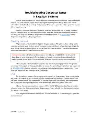
XR2206 Function GeneratorAssembly & Operations ManualBy Steven VagtsZ-100 LifeLineInsert, Issue #132XR2206 Function Generator Description:As I described back in issue #130 of the Z-100 LifeLine, test equipment can be quiteexpensive pieces of hardware, especially for hobbyists or beginners. But fortunately,there are some really cheap Do It Yourself (DIY) kits from China that are availablefor less than 10-20.00 on Ebay.One such kit is the XR2206 Function Generator Kit. The kit does not require a lot ofsoldering experience, so it makes a great learning project in soldering and kitassembly, while also providing a great addition to the electronics workshop. It usesonly though-hole components. Nevertheless, a soldering iron with a needle point tipwould be very helpful here. Additionally, there are silk-screened labels on thecircuit board that show you where each component should be placed.The XR2206 Function Generator can generate three types of stable wave forms (sine,triangular, and square wave) with a frequency range from 1Hz to 1MHz and an adjustableamplitude. It uses an AC/DC power adapter (9-12Vdc, 30mA of current).Please note, this item ships from an international seller. Expected delivery is 10-15days.XR2206 Function Generator Features:******Caution:Based on the XR2206 chip.Small Size: Finished case measures 2.19" wide x 2.81" long x 1.3" highAdjustable Frequency Range: 1 Hz to 1 MHz.Generates three waveforms:Sine Wave: Adjustable Amplitude: 0-3Vdc at 9Vdc input Distortion: Less than 1% (at 1KHz) Flatness: 0.05db 1Hz - 100KHzTriangle Wave: Adjustable Amplitude: 0-3Vdc at 9Vdc input Linearity: Less than 1% (up to 100KHz) 10mASquare Wave: Amplitude: 8V (no load) at 9Vdc input Rise/Fall Time: Less than 50ns/30ns (at 1KHz) Symmetry: Less than 5% (at 1KHz)An easy to construct acrylic case in included.Power Supply Required: 9-12Vdc (not included)At voltages greater than 12Vdc, the output waveform becomes unstable.
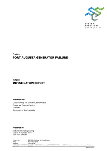
Physical Layout of the XR2206 Function Generator:Power:The XR2206 Function Generator requirespower from an external 5-9Vdc AC/DCpower supply or a 9V battery withmodified cable adapter to connect tothe 2.1mm x 5.5mm power jack. There isno ON/OFF switch. When power isapplied, the unit is ON.Controls:The Function Generator uses threeadjustment potentiometers:***Amplitude AdjustmentFine Frequency AdjustmentCoarse Frequency AdjustmentAssembly:Note: For a full, more detailed article on the assembly of the XR2206 FunctionGenerator, please check out the on-generator-diy-kit-reviewIt was created with the novice in mind,with plenty of photographs.The following description is providedhere in the event that the websitementioned above is removed or becomesunavailable. This description alsoassumes a more experienced hobbyist andwill provide more of a summary ofprocedures, with some details and hintsthat I found were omitted during myconstruction.All the parts needed to construct theTester are provided, with a two page,nearly unreadable instruction sheet.This manual will guide you through therather simple construction and operationof this Generator.A schematic is included at the end.Assembly will require the following tools:Ohmmeter and Capacitor Checker (recommended)Needle tip soldering iron or gunThin electronics solder w/flux coreFine solder wick or desoldering braid for mistakesNeedle nose pliersDiagonal side cuttersPhillip’s head screwdriver5-9Vdc AC/DC power adapter or 9Vdc battery
Before beginning construction, identify and compare the parts you received with thefollowing list. I also suggest that you check those parts that you can with an ohmmeter and capacitor checker, if they are available. All parts are new; however, in thetwo frequency counter kits that I have constructed, I found I was missing a 3-pinheader and had an extra push button switch. In the other China kits that I haveconstructed so far, I also found a shorted capacitor and a resistor included in onekit of the wrong value. A little extra time here to check components now, will saveconsiderable time trying to troubleshoot a malfunctioning assembly.Parts List: (Numbers in parentheses show component JK1J1,J2P1Component Description:330 ohm, 1/4W, 1%, Metal Film Resistor1K ohm, 1/4W, 1%, Metal Film Resistor5.1K ohm, 1/4W, 1%, Metal Film Resistor50K ohm (B503), Adjustable Potentiometer100K ohm (B104), Adjustable Potentiometer100pF, 20%, (101), Ceramic Capacitor2200pF, 20%, (222), Ceramic Capacitor0.047uF, 20%, (473), Ceramic Capacitor0.1uF, 20%, (104), Ceramic Capacitor1.0uF, 20%, (105), Ceramic Capacitor10uF, 20%, Aluminum Electrolytic Capacitor100uF, 20%, Aluminum Electrolytic CapacitorXR2206, Integrated CircuitDC Jack, 2.1mm (ID) x 5.5mm (OD)Jumper cap, 2-pin, XM2.54Connector Block, 3-pin, screw typeMain Circuit Board, 3" x 2.4"10-pin double Header4-pin double HeaderAcrylic Case PartsMachine Screws, 3mm x 15.8mmMachine Screws, 3mm x 6.35mmNuts, 4[4[4[]]]]]]]]]]]]]]]]]]]]]]]Assembly Procedures:Begin assembly by inspecting the bare board.Get a feel for the layout of the parts,part numbers, and what is going to gowhere. The component side is the sidewith the silk screening, and while theremay be some silk screening on the solderside, for our small kits, all the partswill be installed on the component sideof the circuit board (left board in thepicture).Hint: I always suggest installing thosecomponents with the lowest verticalprofile first. This keeps the circuitboard flat and stable for as long aspossible during the assembly andsoldering process. So, I usually startwith any surface mounted components,while the board is empty and moststable. This kit does not have any.Hint: Using a spare cotton towel under the circuit board helps protect the worksurface and stabilize the board during soldering.
Hint: All the solder pins on this board are adequately separated, however, if youaccidently create a solder bridge across 2 or 3 pins, place solder wick over thesolder bridge and carefully heat the wick only until solder flows into the wick.Take care not to overheat the component!As this kit has no surface mountedcomponents, begin with installation ofthe resistors. You may install them oneat a time, but I suggest inserting allthe resistors, bending the leadsslightly to keep them in place. Thenturn the board over and solder all theleads at once, clipping off the excessleads as you go.For a small project such as this, thegroup method also ensures that all ofthe resistors are of the correct value,used correctly and in their properlocation, BEFORE soldering any in place!Next, install the ceramic capacitors(next in the height profile) and use thesame techniques we used for theresistors - inserting them all, bendingthe leads to ensure they stay in place,then soldering and clipping the leads atone time, if you desire.Next, install the IC socket.Hint: When you install multi-pin components, such as the 16-pin IC socket, alwayssolder one lead at each end of the component first, check to insure the component isfully inserted in the board (not tilted to one side or one end is not fully seated),before soldering the remaining pins. It is much easier to fix a tilted socket withonly one pin to heat to reposition the socket.When installing the 16-pin IC socket,watch for the half-moon notch on oneend! Install the socket so that thisnotch is over the similar notch symbolon the silk-screened circuit board. Donot install the IC until after the restof the components have been installedand the solder side of the board hasbeen inspected and cleaned.Install the electrolytic capacitors andany transistors (there are no transistors in this kit).
The next parts (in height profile) arethe DC jack at position JK1, the 3-pinscrew-type connector terminal at positionP1 and the 10-pin and 4-pin headers.We have only the potentiometers left toinstall and we leave them to last toavoid damage during cleaning.It is time to visually check your worklooking for solder bridges, parts withcold solder joints (meaning a poorconnection; not having the same appearance of smooth solder flow as the othersolder joints), or open, unsolderedjoints.If you have an ohmmeter, check joints near each other for shorts.Next, clean the solder side of the board. Many use a special flux cleaner product toclean the soldering side. Personally, I check each solder connection and use a finescrewdriver or dental pick to scrape away any flux residue, then use a damp toothbrushto remove the scraped residue.When you are satisfied that the boardis as good as you can make it, it istime to install the three adjustablepotentiometers. Double check the valuesstamped on the sides of each unit andplace in their respective holes.Install the integrated circuit, lookfor a dot or notch to indicate wherepin 1 is located. Watch that you do notbend any pins under as you carefullyinsert the IC into its socket (seeHint, next).Hint: IC's generally come with their pins spread apart just a little further than thewidth of the IC socket. You can carefully bend these pins closer together by placingthe IC on its side on the work table, and gently pressing the pins toward the centerof the IC by rotating the IC just slightly. Do the same with the other side.Leave the knobs until testing is completed and you are ready to assemble the case.Congratulate yourself on a fine job!
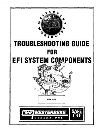
Operation:Operation is simple. There is no ON/OFF switch. Plug in the 5-9Vdc power supply or a9v battery with a cable adapter and the device turns ON.The frequency generator comes with three knobs. One for amplitude adjustment, andother two for fine and coarse frequency adjustment. There’s a jumper cap you use toselect a frequency range. The other jumper cap should be placed to select one of thethree waveforms for the output.To test the function generator, apply a 9 to 12V power supply. You will need anoscilloscope to test this kit, such as the low-cost DSO138 digital oscilloscope, whichwill be reviewed in another, future issue. This following pictures are from my Z-100Heathkit Digital Scope.Here are the sinusoidal (left), triangular (right), and square wave signals.The function generator performed quite wellproducing very stable sinusoidal, triangularand square wave signals. When testing thekit, we have noticed that the leading edgeof the square wave was slightly rounded(possibly due to the length of the inputcable).
Theory of Operation:The heart of this circuit is the integrated circuit XR-2206, which has a structureconsisting of three main parts.1. Voltage Control Oscillator (VCO) that has a frequency that depends upon the valueof the capacitor between pin 5-6 and the resistor between the pin 7-8.The output is a synchronous signal or a square wave signal. The synchronous signal issupplied to the management waveform circuit.2. The Management Waveform Circuit permits having a sinusoidal waveform or atriangular waveform as required by changing the resistance of the legs 13-14.3. The Buffer Circuit is responsible for managing the output impedance of the circuitat low values, and for the extension to other circuits as well.From the generic XR2206 function generator circuit shown, it can be seen that switchS1 selects the frequency range by selecting the capacitance value between pins 5-6:* 1-100 Hz* 100-10,000 Hz* 10,000-1,000,000 HzAdjust the frequency desired by changing the value achieved by the VR3.Next, VR2 is used to adjust the gain ratio of the circuit by the fine control, VR1, toget the maximum output 1V. Then VR5 is adjusted to balance the waveform.Switch SW2 is selects the signal output of a sine wave or sawtooth waveform.The signal output is entered through the buffer circuit Q1 and Q2 to C9.For the square wave signal, output will be out to pin 11 of IC2, and then to thetransistor buffer circuit for output at the emitter pin. The square wave signal willhave a signal strength of about 12 volts peak to peak, depending upon the inputvoltage. So if you want to use TTL circuits using a 5Vdc voltage, you must add a DCconverter circuit with IC-SN74LS00.
How to Use a Function GeneratorA function generator is generally used for testing the response of circuits to commoninput signals. The function generator produces a variety of voltage patterns atdifferent frequencies and amplitudes. You connect the function generator’s electricalleads to the ground and the signal input terminals of the device under test (DUT).Function Generator Controls:* Amplitude Control: The Amplitude Control changes the signal strength, whichis the voltage difference between the output signal’s high and low voltage. Its directcurrent (DC) offset control changes the signal’s average voltage with regard to theground.* Frequency Control: Frequency Control is used to manipulate the outputsignal’s rate of oscillation, and may have two controls; one to select the frequencyrange and another to select an exact frequency. This enables the function generator tohandle the dramatic variation in frequency scale required for signals.* Waveform Select: This control selects the type of waveform desired. Moreadvanced waveform generators use direct digital synthesis techniques to generate anywaveform and, in addition to the three basic waveforms of ours, often includewaveforms like ramp, noise, and pulse as well as specialized waveforms.* Duty Cycle: The Duty Cycle is its ratio of high to low voltage time, as itconcerns square wave signals. The XR2206 does not include this.You use a function generator by powering it on and configuring the output signal toyour intended shape. This will require connecting the ground and signal leads to anoscilloscope to check the controls. You adjust the function generator until you getthe appropriate signal and attach the function generator’s ground and signal leads tothe device under test’s input and ground terminals.To see our Function Generator in action, we need our XR2206 Function Generator, anoscilloscope and a device or circuit that you wish to test. For my testing I usedthree of my kits - the XR2206 Function Generator, the DSO138 Oscilloscope, and theDL4YHF2 Frequency Counter, as pictured:Just power ON thegenerator and selectthe desired outputsignal: square wave,sine wave or trianglewave.Connect the outputleads to an oscilloscope to visualizethe output signal andset its parametersusing the amplitudeand frequencycontrols.Attach the outputleads of the functiongenerator to theinput of the circuityou wish to test - inthis case, thefrequency counter.
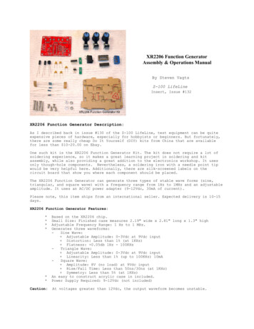
In the closeup on the left,you can see the waveform andthe frequency on the frequencycounter match nicely.For more information on theother kits in the picture,please refer to theirrespective articles on mywebsite:z100lifeline.swvagts.comPlease note the 0.1uF capacitor on the output of the XR2206 Function Generator. When Ifirst put this circuit together, I was very disappointed with the DL4YHF2 FrequencyCounter. While the oscilloscope showed that the waveform was nicely square and stable,the frequency counter would not stabilize, if I got any frequency at all! Yet, when Iused the frequency counter to test an oscillator, it was nicely stable at the correctvalue.Looking at the circuit diagram for the DL4YHF Frequency Counter, I saw that thecircuit for the crystal & oscillator tester used a 0.1 uF capacitor to eliminate anyunwanted DC voltage. But for the input of external frequencies, a capacitor was notincluded. Perhaps a cyclic DC voltage was confusing the counter?So, on a whim, I included a 0.1 uF (104K) capacitor (type is not critical) at theoutput of the generator.The capacitor fixed the unstable counter, as you can see - a nice solid 3.020 KHzdisplay, but I found that at the much higher frequencies, the waveform was distortedby the charging and discharging capacitor.I moved the 0.1 uF capacitor to the input of the frequency counter, between the inputjack and the circuit board, and now all the test equipment were happy. I have includedthe new capacitor in an update to the DL4YHF2 Frequency Counter article.
Final Assembly:With testing complete, remove the papercover from the case pieces and assemblethe acrylic case using the hardwareprovided.The smaller screws and nuts are onlyused on the circuit board to provide aspacer for the bottom of the circuitboard. Trim off any lengths of wire thatare too long and interfere with thecircuit board sitting flat on the bottomcover.Place the four sides in the slots of thebottom cover, insuring that the shortsides are correctly installed and notblocking the access to the power jackand terminal block.Use the longer screws to attach thecover to the base while trapping theside pieces between the covers. Theholes of the bottom cover are threaded,so no nuts are required.Conclusions:This is a simple circuit giving excellent performance given its price. For less than 15 dollars you can get a function generator with amplitude and frequency adjustment.The XR2206 function generator DIY kit is great for electronics hobbyists for repairingand debugging circuits, and for learning purposes. The kit comes with through-holecomponents, and it is easy to solder and assemble. You can have it built inapproximately half an hour. While it could never provide the functions of a high-endfunction generator, for most purposes of a hobbyist, it is an excellent product.To take full advantage of this unit, you should also invest in a reasonably pricedoscilloscope kit, such as the DSO138 and DSO150, which will be reviewed in futureissues of the “Z-100 LifeLine”.Enjoy.If you have any questions or suggestions, please contact me at:z100lifeline@swvagts.com
of the circuit board (left board in the picture). Hint: I always suggest installing those components with the lowest vertical profile first. This keeps the circuit board flat and stable for as long as possible during the assembly and soldering process. So, I usually start with any surface mounted component