Transcription
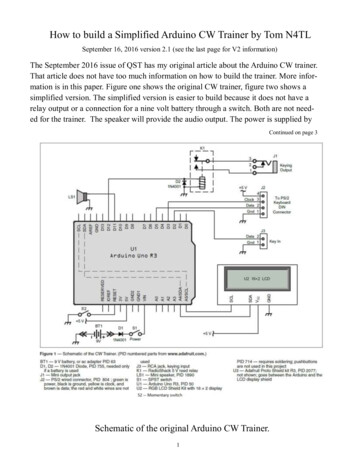
12-Volt Alternator Installation& Operation ManualIntroductionThank you for choosing a Balmarr high-output alternator. This alternator is uniquely engineered to provide the finest performance and durability for your vessel. Unlike most automotivetype alternators found standard on the majority of pleasure craft and marketed as lower-priced marine alternatives,our marine alternators provide exceptional output at lower engine r.p.m’s typical of marine diesel engines, so youcan enjoy shorter charge cycles, greater economy, longer battery life and less noise and fumes.When used in conjunction with Balmar microprocessor-controlled Max Charge and ARS-Series multi-stage regulators, your Balmar alternator provides even greater efficiency when charging deep-cycle flooded, standard flooded,gel, AGM, Optima and other marine battery technologies. When preset for your battery type, the smart regulatorguides your alternator through a tailored charge cycle that ensures the best care possible for your batteries. Balmarmulti-stage regulators provide the ability to monitor temperature at your alternator.ContentsWhen used with the optional alternator temperature sensor (MC-TS-A) installed, theIntroduction .1regulator will automatically reduce field output to 50 and activate a warning circuitSafety Considerations.1which can control a user-installed visual or audible alert, should an over-temperatureBasic Installation .2condition occur. Together, the Balmar high-output alternator and multi-stage regulaAlternator Mounting .2Addl. Information .3tor work to assure the best charge possible.Sizing Battery Cables .3Selecting Drive Belts .4Vottage Regulation .4Fan Rotation .4Grounding .5Pulleys .5Alternator Heat .5Meters .5Charge Lamp .5Tachometers .6Fusing .5Alternator/Battery Ratios .5Multi-Bank Options .6Switches .7Combiners .7Isolators .7Digital Duo Charge .7Twin Engine Issues .8Centerfielder .8Twin Engine Diagram .9System Troubleshooting.10-11Terminal Connections .12-146-Series .127-Series .128-Series .1294-Series .1295-Series .1297-Series .1298-Series .12Warranty.14Appendixes .15-162008 - Ballard Comm.Industries, Inc.Safety ConsiderationsBefore installing your new alternator, please take a moment to consider the followingguidelines for safe alternator installation and operation. Failure to follow these guidelines could result in injury or damage to your vessel’s electrical system.1.Always disconnect your batteries and turn your battery switch to its “OFF” position prior toinstalling your alternator.2.Remove any loose fitting clothing or jewelry which could become entangled in your motor orother machinery.3.Wear ANSI-approved safety glasses or eyewear.4.Ensure that the engine has cooled sufficiently before beginning installation.5.DO NOT install your high-output alternator without ensuring that the system wiring is sufficiently scaled to handle increased amperage loads.6.Be sure that your work area is sufficiently ventilated and that no fuels or solvents are present in and around your work area.7.DO NOT operate your charging system without proper fusing. Failure to do so could resultin severe injury and/or damage or loss of your vessel. DON’T take chances with fusing.8.DO NOT attempt installation while using alcohol or medications which could impair yourjudgement or reaction time.9.Use the right tool for the job. Use of improper tools could result in damage or injury.10. Take time to read the manual. Equipment damage and possible injury may result from anincomplete understanding of the proper installation and use of the alternator.CAUTION: The following instructions are intended for use by experienced marineelectrical installers. If you are not sufficiently experienced with marine electrical systems, we recommend a qualified electrician be used for installation.
Installation InformationBasic InstallationAlternator MountingDue to the many domestic and international configurations of engine/alternator mounts, andfactors such as year and location of engine manufacture and marinization, Balmar cannotguarantee a drop-in replacement in every engine application. Choose the model that mostclosely fits your application. Your installer may have to adapt the basic mounts to fit yourneeds. The majority of marine engines are equipped with one of four alternator mountingstyles. The following describes which alternators represent each specific mounting style:1. 60 & 70-Series (Dual Foot w/3.15” between legs): Small Case. Replaces most small case styles usinga saddle style mount (eg., Hitachi, Lucas, Mitsubishi).2. 621, 71 & 81-Series (1'' Single Foot): Small Case. Replaces most domestic styles using a single 1"mounting foot (eg., Motorola, Prestolite). Note: 621-Series alternators provide a bushed spacer toconvert from 1” to 2” single foot mount.3. 621, 712 & 812-Series (2'' Single Foot): Small Case. Replaces most domestic styles using a single2" mounting foot (eg., Delco). See note above for 621-Series alternators.4. 622-Series (2'' Pad Mount) Series: Small case. Replaces Korean (Mando type) alternators using dual2” static pad mounting feet. (Found on many Mercruiser and Volvo Penta gas engines.)5. 94-Series (2'' Single Foot) Series: Large case. See dimensions in our Product Guide or at our websiteto determine if your engine can accommodate a large case alternator.6. 95-Series (Dual Foot w/4'' between feet) Series: Large case. See dimensions in our Product Guide orat our website to verify if your engine can accommodate a large case alternator.7. 96, 97 & 98-Series (Dual Foot w/4'' between feet) Series: Extra large case. See dimensions in ourProduct Guide or at our website to determine if your engine can accommodate a large case alternator.If you determine that the desired alternator will just not replace the existing alternator, oneexcellent option may be to leave the existing alternator in place and purchase a dual groovecrank pulley for the front of the engine (in addition to the existing pulley). Have a specialmount fabricated, or use the Balmar Off-Engine Alternator Bracket (Model 5276) to accommodate a larger alternator.Once you have determined that the new alternator is the correct replacement for your existing model:1.Disconnect the batteries and/or turn the switch to the “OFF” setting. Disconnect the wiring from theexisting alternator.2.Loosen the mounting & tensioning bolts and remove the existing alternator.3.Once the alternator is disconnected from the engine, compare its mounting points to those on yournew Balmar alternator. In most applications, the new alternator will replace the old alternator without any modification. In some cases, a simple bracket can be fabricated by a local machine shop.Balmar offers a universal mounting arm which can replace your existing tensioning arm, if needed.Others can be obtained through your local auto or marine supply.4.Attach the mounting foot of the new alternator to its engine mount. Some shimming may be necessary to ensure that the alternator is securely mounted within the engine mount. If your alternator isa dual foot style, use care when tightening the alternator in place that the two mounting ears are notcompressed. The rear bushing is designed to slide to tighten the mount.5.Once in place, inspect to ensure that the alternator pulley is properly aligned with the engine pulley.If your belt configuration includes the pulley for the water pump, make sure that all three pulleys areproperly aligned. Some shimming or modification to the alternator mount may be required to assureproper alignment.6.Connect the output cable (see cable sizing recommendations below) ground, field wire, stator (tach)wire if needed and other necessary wiring. Connect alternator to Balmar regulator wiring harness asindicated in wiring diagram included on Page 12. The alternator’s positive and ground cables shouldbe sized according to the chart on Page 3.Page 2
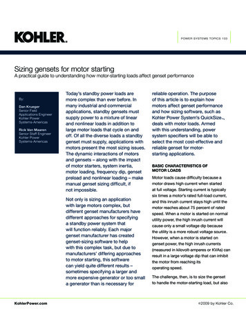
Page 37.Belt Adjustment/Battery CablesIf a new regulator is being installed along with the alternator, complete its wiring installation according to the instructions included with your regulator.After the alternator is installed and the wiring connections are attached, inspect for proper belt tension. When changing pulleys or when using the factory-installed pulley, torque the shaft nut to 50-60 foot-pounds. The shaft nut measures 15/16''. To install the belt:1. Loosen the adjustment arm bolt and alternator pivot assembly bolt.2. Fit a new, high-quality belt over the appropriate pulleys.3. Tension the alternator until the belt is securely tightened in place. Re-tightenthe pivot assembly and tension arm bolts. To test tension, place a 15/16''wrench on the alternator shaft nut and apply pressure. If the pulley rotateswithout moving the belt, re-loosen the bolts, apply additional pressure andre-tighten. Repeat until the belt is properly tensioned.4. Verify proper tension by pushing on the outside surface of the belt. The beltshould deflect approximately 1/4” to 5/16” under moderate pressure. Yourlocal auto parts store may carry a measuring tool designed to gauge beltdeflection.5. Ensure that the mounting bolts at the alternator’s tensioning arm and pivotpoint are securely re-tightened.For ease of belt installation, invest in an inexpensive belt tensioningtool like that sold by J.C. Whitney. This simple tensioner (Model #ZX156161X) provides positive support at the alternator while increasing belt tension, leaving two free hands to re-tension mounting and tensioning belts. DO NOT usea bar or other device to pry the alternator case into place, as damage to the alternator may occur.New belts tend to stretch during the first several times you run your engine. Make it a part of your normal pre-flightcheck to test belt deflection and re-adjust belt tension as needed. If you notice significant black dust on your alternator and surrounding engine area, check belt tension. If the belt is properly tensioned and you still experience beltdusting, it may be necessary to reduce horsepower load with the Max Charge regulator’s Amp Manager, orARS-5 regulator’s Belt Load Manager. See your regulator manual for programming instructions.Additional Installation InformationSizing Battery CablesIt may be necessary to increase the size of your batterycables to support the added amperage output of the Balmaralternator. The chart to the right indicates cable gaugerequired to handle current loads. When determining wirelength, the “round-trip distance” both positive and negativewire runs between the alternator and the batteries beingcharged must be considered.Length (feet)Amps7510012515017551015 20 2530 40 50 75864228422164216211/0 2/0 3/0 4/06211/0 2/0 3/0 4/0200225250421/0 2/0 3/0 4/0411/0 2/0 3/0 4/0412/0 3/0 4/011/0 2/0 4/03/0 4/01/0 3/0 4/0Should greater accuracy be desired in determining the opti- 27541 2/0 3/0 4/0mal wire gauge, the following formula can be used: CM K2 1/0 3/0 4/0300x I x LE (whereas CM represents the circular mil area of the2 1/0 3/0 4/0conductor, K represents the mil-foot resistance of copper, I 350represents current, and L represents the length, in feet, of the round-trip cable run and E represents voltage drop involts). When using this equation, a K constant of 10.75 indicates copper’s mil-foot resistance and voltage dropshould be calculated at 3% (the standard for critical functions affecting the safety of vessel passengers.In addition wire gauge and quality, the quality of wiring connectors and terminations can have a direct effect oncharging efficiency and safety. Be sure that all cable connections are secure and in excellent condition prior to operation of the charging system. Failure to do so could result in decreased performance, damage to the charging system or batteries, or in overheating and potential electrical fire. NEVER operate your charging system if you haveany concerns about the capacity or condition of your electrical wiring.
Belts/Regulation/Fan RotationPage 4Selecting Drive BeltsThe added horsepower load of your Balmar alternator will increase stress on your engine’s drive belt. This additional load may require that you replace the standard drive belt with a heavier-duty belt. Many aftermarket belt manufacturers supply premium-quality belts, designed specifically for heavy-duty marine and industrial applications.Among these are the Green Stripe belt by Gates, Gator Belts by Goodyear, and the Top Cog belt from Dayco. Manyauto parts suppliers, such as NAPA, carry extra heavy-duty belts designed to support larger horsepower loads.In addition to belt quality, belt size can have a substantial impact on alternator performance. We recommend a minimum 3/8” belt (measured across the back of the belt) for alternators up to 80-amp output. Minimum belt width foralternators up to 110 rated amps is 1/2”. Any alternator larger than 110-amps will require dual belts, or multi-grooveserpentine belts for optimal performance, as well as acceptable belt life.The addition of a larger diameter alternator pulley can often improve belt wear, as it will increase belt wrap and surface contact with the belt -- though the increased pulley diameter will lessen the ratio between the alternator andflywheel pulley and reduce low end amperage output.Should you find that your belt is undersized for your alternator, the Amp Manager mode, available in the Max ChargeMC-612 (12-volt) and MC-624 (24-volt) multi-stage regulators, enables you limit the maximum field potential ofthe regulator and limit the horsepower load of the alternator. This feature,accessible through the Max Charge’s advanced programming mode, can be Belt Manufacturer Websitesadjusted in precise 2% increments -- so output can be adjusted to suit theGates - www.gates.comsystem without losing more charging current than necessary. For more inforDayco - www.dayco.commation, see the manual included with your Max Charge MC-612 or MCGoodyear - www.goodyear.com624 regulator. Many engine manufacturers can provide replacement pulleysFenner - www.fennerindustrial.comto convert your drive system to support dual belts.Voltage RegulationWith the exception of our 6-Series alternators, which feature patented “Smart Ready ”” internal regulators, Balmar high-output alternators require external regulation in order to operate. We recommendour multi-stage ARS-4 and Max Charge regulators to provide optimal,balanced charging for most marine battery technologies. Whenordered with supplied wiring harness, the voltage regulator can bemounted on a stringer or bulkhead up to four feet from the alternator.Excessive heat and exposure to coolant or saltwater can damage theregulator. Consider that when determining regulator placement.ABCBalmar’s standard regulator wiring harness measures 54”, and features ring terminal connectors at the alternator, or plugs (as seen at NOTE: Some alternators may use ring terminalsright) depending on which alternator is being used. The flat plug, rather than plugs for stator and field connections.indicated by the letter “A” is used with our 95-Series alternators, thegrey rectangular plug, indicated by the letter “B” is used with our 6-Series and 9-Series alternator models. The black,T-shaped plug, indicated by the letter “C”, is designed for use with our 94-Series alternators. All 7-Series, 8-Series,97-Series, 97EHD-Series and 98-Series alternators use ring terminal connectors.Fan RotationBalmar alternators are designed to turn in a clockwise rotation. Face the front of the engine with the engine runningto determine direction of rotation. Internally fanned 6-Series alternators are designed for clockwise rotation only.7-Series model styles can typically be run in either direction (15% to 20% cooling loss may occur). 94-Series, 95Series, 97-Series, 97EHD-Series and 98-Series feature bi-directional fans and keyed pulleys, so reverse rotation isacceptable.8-Series and out-of-production 90, 91, and 912-Series alternators may require a reverse-rotation kit for counterclockwise rotation applications. Keep in mind, alternators with non-keyed shafts will require pinning to ensure proper performance. A long twist drill bit and a roll pin are included in the reverse rotation kit.
Page 5Grounds/Pulleys/Heat/MetersGroundingMost Balmar models are designated as Isolated Ground (IG), and feature an independent ground terminal that’s isolated from the alternator case. It is essential that a dedicated ground cable, equal in gauge to the alternator’s positive output cable, is installed between the alternator’s ground terminal and the electrical system ground. This canbe to a primary ground bus, battery ground terminal, or the engine block if it is connected directly to system ground.Failure to connect the alternator to system ground could result in damage to the ship’s electrical system, alternatorand voltage regulator. Case ground alternators may access ground through the engine block, although it is recommended that a dedicated cable be connected between the alternator’s ground terminal and system ground to ensureoptimal continuity.PulleysMost small case alternators rated at 110 amps or less come standard with a single groove deep vee pulley. The deep vee pulley is designed to provide optimalpower transfer for belts measuring 3/8” (10mm) to 1/2” (13mm), as measuredacross the back of the belt. Keep in mind, 3/8” and 7/16” belts may sit low inthe pulley sheave. This will not adversely affect the belt’s performance. Higheroutput alternators (120 amps) in small, large and extra-large case seriesare equipped standard with 1/2” dual groove pulleys. Some models, including 622-Series alternators may be equipped with multi-groove serpentinetype pulleys. Should your application require a different pulley than that provided as standard, Balmar may carry an optional pulley more suited to yourneeds. For a list of optional pulleys, visit http://www.balmar.net/pulleymatrix.htm,or call Balmar Customer Service at 360-435-6100.Alternator HeatDuring operation, your alternator will become hot as a result of friction and the generation of inductive current. Insome instances, particularly during extended periods of heavy load, alternator case temperature can exceed 200degrees (F). If your system is operating with an ARS-5 or Max Charge MC-612 voltage regulator with optionalAlternator Temperature Sensor (MC-TS-A), the regulator will automatically reduce the alternator output by approximately 50% if temperatures exceed set safe working limits (approximately 225oF. While this is an extremely effective protection for the alternator, it should not be depended upon as a part of normal operation. Correction of conditions causing overheating are strongly advised.Use extreme caution when handling the alternator or other engine components during or after use. Should your alternator become so hot that it emits a burning smell, or if there is indication of discoloration at the pulley or pulleyshaft, shut off the alternator immediately and (once it becomes safe to inspect the alternator) check the tension ofthe drive belt. Under- and over-tensioned belts are the leading cause of overheating and alternator damage. See theTroubleshooting section, later in the manual, for alternator inspection guidelines. In applications where airflow to thealternator is limited, consider providing ducted air from a cool source (such as the bilge, or from an external vent)to the rear of the alternator. This will provide a pronounced improvement in cooling efficiency.MetersReplacing your standard alternator with a high-output Balmar alternator may require that your standard amp meterbe replaced with a high amperage, shunt-type meter. We strongly recommend replacing your amp meter with a morefully functioning charging system monitor, such as the Link Meter from Xantrex/Heart Interface. In addition to metering system current, these system monitors will indicate battery condition and estimate battery time remaining beforecharging is needed.Charge LampsDepending on your application, your dash-mounted charge indicator lamp may be controlled by a diode trio (D )circuit provided by the alternator. 6-Series alternators provide a D terminal to activate the lamp circuit. If yourBalmar alternator does not include a D terminal, your Max Charge or ARS-5 voltage regulator provides a DashLamp circuit which may be capable of activating the charge lamp. See your regulator manual for more information.
Tachs/Fusing/Charge Ratios/Multi-Bank issuesPage 6TachometersAll Balmar alternators provide a source of un-rectified AC voltage directly from the stator output. This stator output provides the pulse requiredto drive most electric tachometers. Most current Balmar alternators feature 12-pole stator outputs (meaning 12 pulses of AC voltage duringeach alternator revolution). Extra-large case 98-Series and older 9-Seriesalternators feature 14-pole stator outputs.Tach Manufacturer WebsitesTeleflex - www.teleflexmarine.comVDO - www.vdo.comStewart Warner - www.stewartwarner.comISSPRO - www.isspro.comMost electrical tachometers feature some level of adjustment to calibratethe tachometer to your alternator’s pole settings and pulley ratios. If your existing tachometer does not provide anyadjustability, it may be necessary to replace the existing tachometer with an adjustable model.FusingThe American Boat and Yacht Council (ABYC), in its standards for safer boating, recommends that cable runs to yourbattery banks be fused to protect the boat and owner against damage and injury. Circuit protection, as described byABYC standards, can be accomplished by installing either a resettable circuit breaker or a fuse. The fuse or breakeryou choose will depend on both the length and the size of cable used. Blue Sea Systems, a respected manufacturer of high-quality fuses and circuit breaker devices, recommends the following when sizing the proper circuit protection for your system. Fusing should be:1. The largest available circuit protection device smaller than the amperage capacity of the cable being protected.2. Larger than the maximum continuous current that will flow in the circuit.Note: Fusing is designed to protect the boat and its wiring from the constant potential energy stored in the battery, rather than output from the alternator. Fusing should always be installed at the end of a wire or cable runclosest to the battery. DO NOT place fusing for the alternator’s output cable at the alternator end of the cable run!We find that a circuit protection device sized at approximately 140% of your alternator’s rated amperage is typically suitable for the circuit being protected. For more info about circuit fusing, see attery RatiosIn order to achieve optimal performance from your charging system, it is essential to determine the capacity yourcharging system is capable of supporting. In general, the size rating of the alternator should mirror the acceptancerate of the batteries being charged. Differing battery technologies will vary in terms of their acceptance rates. Forexample, a deep-cycle flooded battery is typically capable of accepting roughly 25 percent of its available capacityat any given time. As a result, we want our alternator’s rated output to equal the acceptance rate of the battery beingcharged when it reaches its full discharge rate. In other words, a deeply discharged 400 amp hour deep cycle flooded battery would require an alternator rated at 25 percent of 400 amps, or 100 amps to support that bank.In simpler terms, a deep-cycle flooded battery bank will require 25 amps of alternator output for every 100 amphours of battery rating. Some newer battery technologies, such as AGMs and spiral wound batteries can accept upto 40 percent of their available capacities, as such, alternator output should be increased to reflect the optimal ratiobetween alternator and battery capacity.Failure to meet recommended alternator-to-battery ratios will commonly result in slower charge times, increasedalternator heat and wear, and reduced alternator life.Multiple Bank Charging OptionsWhen charging a single starting battery, the alternator can be connected to the battery directly, or via an ON/OFFswitch. In marine charging systems, the alternator typically supports a smaller starting battery and larger house battery bank -- or multiple banks dedicated house loads, inverter loads, as well as windlass or thruster batteries. Manymethods of multi-bank charge control are available, ranging from manual switches to products like Balmar’s DigitalDuo Charge, which automatically provides charging current to the starting battery whenever charging voltage is present at the house battery.The following section outlines many of the most commonly used options for multiple-bank battery management:
Page 7Multi-Bank Charge ControlSwitchesAvailable in two primary types -- ON/OFF or A/B/BOTH -- manual switches offer a simple method for managing battery charging. Possible installations include separate cables to each battery bank with ON/OFF switches in line foreach bank, or, a common output cable to the common post of the A/B/BOTH switch with an output cable to eachbattery bank. Field disconnect switches feature terminals where the field output from the regulator to the alternatorcan be interrupted when the battery switch is turned to the OFF position. This feature ensures that alternator output is discontinued as soon as the battery is disconnected. NOTE: NEVER operate the alternator with all switchesin the OFF position (doing so will damage the alternator).Advantages:Inexpensive. No substantial voltage drop.Disadvantages:Require user interaction and heightened system understanding. Can be accidentally shut down, causingpotential alternator damage. Does not allow for mixed battery technologies.Voltage Sensing:Battery voltage sensed must always be that of battery being charged. Sense voltage at common side of battery switch or at alternator positive output.Battery CombinerBattery combiners enlist high-amperage solenoids to charge multiple battery banks. Below a specific voltage setpoint, the combiner’s solenoids remain open, isolating the individual battery banks. Once the baseline voltage isreached, the solenoid(s) open, combining all of the batteries into one big bank.Advantages:No user interface required. No substantial voltage drop. Available in 2 or 3-bank models.Disadvantages:Moderately expensive. Does not allow for mixed battery technologies.Voltage Sensing:Sense voltage at common side of combiner or at alternator positive output.Diode IsolatorIsolating diodes direct charging current to the battery bank with the greatest demand. Best suited for battery banksthat are comparable in size and degree of discharge. Isolators are not necessarily the best choice when charginghouse and start battery banks. Only one battery bank can be sensed by the regulator, so under- or over-charging canbe a substantial issue if batteries are dissimilar in capacity or degree of charge. Diodes can drop voltage at the battery side of the isolator by nearly a volt, which means that the alternator is forced to increase voltage far in excessof that needed by the batteries.Advantages:No user interface required. Reasonably priced. Available in 2 or 3-bank models.Disadvantages:Substantial voltage drop. Can only sense voltage at one battery bank. May drive voltage at secondary battery bank to dangerously high levels. May hold high voltage for too long at smaller bank. Tendency to underor over-charge secondary (non-sensed) battery bank. Greater chance of early battery failure.Voltage Sensing:Voltage must be sensed at most commonly used battery bank (typically house). Connect sense wire to battery side of isolator or positive post of battery being sensed.Digital Duo ChargeBalmar’s Digital Duo Charge connects between the house and start (secondary) batteries -- keeping the two banksseparate until the unit senses 13 volts (26@24V) at the house battery. Once voltage is reached, the Duo Chargesupplies up to 30A to the secondary bank. Voltage is regulated at the secondary bank based on a preset programchosen by the user to reflect the secondary battery type. Standard and deep cycle flooded, gel and AGM batterytypes are supported. Optional battery temperature sensing and solenoid drive are included. 12 or 24-volt settings.Advantages:No user interface required. Selectable programs ensure proper voltage control -- even with varied batterybank capacities and mixed battery constructions. Amperage limits require smaller wire gauge. Works withDC or shorepower charge sources. Simplifies charging control for alternator and regulator. Can be used tocontrol an optional solenoid to support battery banks with demands greater than 30 amps.Disadvantages:30-amp maximum output may not support larger secondary banks (bowthruster, windlass, etc.) without useof manual solenoid control.Voltage Sensing:Duo Charge senses source battery voltage at positive input terminal. Secondary (starting) battery voltage issensed at the Duo Charge’s positive output terminal. ON/OFF voltage can be monitored at the house battery bank, or at the ignition switch. Visit the Manuals Page at the Balmar website for detailed Digital DuoCharge installation and operational information
Multi-Bank Charge ControlPage 8Two Alternators/Single EngineShould more chargi
Feb 12, 2016 · to determine if your engine can accommodate a large case alternator. 6. 95-Series (Dual Foot w/4'' between feet) Series: Large case. See dimensions in our Product Guide or at our website to verify if your engine can accommodate a large case alternator. 7. 96, 97 & 98-Series (Dual Foot w/4'' b