Transcription
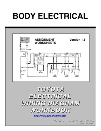
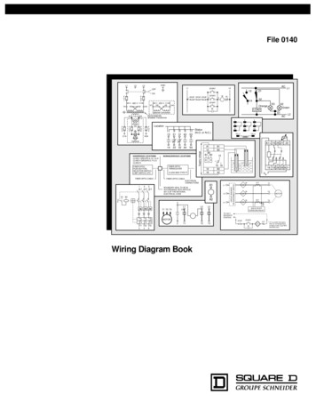
File 0140L1L2GNDL3L1OFFFU1FU2460 VH1H3230 VH2H1H4H3H2A1B115B2B2STOPB3STOP STOP1B115Supply voltageONH4START2MOL316 18B3A21618ElectrostaticallyShielded TransformerFU5PowerOnFU6X1AFU4HML2131 4353142232 4454AC1Status(N.O. or N.C.)25689101214 ( )13 (–)A1/ 15 25 Z1 Z2NONHAZARDOUS LOCATIONSFIBER OPTICTRANSCEIVERSupply voltageFIBER OPTICPUSH BUTTON,SELECTOR SWITCH,LIMIT SWITCH, ETC.A115B2B1 B315H16 18B3A21618CLASS 9005 TYPE FTB1B216 18 26 28 A2/–LMVs2 LevelsFIBER OPTIC CABLEELECTRICALCONNECTIONS135L1 L2 L3A1BOUNDARY SEAL TO BE INACCORDANCE WITH ARTICLE501-5 OF THE NATIONALELECTRICAL CODEL2A1 A2A2L33L1T1 T2 T3L21CTML1CIRCUIT BREAKEROR DISCONNECT SWITCHFIBER OPTIC CABLEL24OptionalHAZARDOUS LOCATIONSCLASS I GROUPS A, B, C & DCLASS II GROUPS E, F & GCLASS IIIX2GreenX1M2 Optional ConnectionX1 115 V X2ACL2STARTT1T2MMOTOR3CTML3T3SOLID STATEOVERLOAD RELAY1TO 120 VSEPARATECONTROLMOTORSTOP2T1T1 T2 T3246Wiring Diagram BookT2STARTOT*T3MM* OT is a switch that openswhen an overtemperaturecondition exists (Type MFOand MGO only)
TRADEMARKSQWIK-STOP and ALHPA-PAK are registered trademarks of Square D.NEC is a registered trademark of the National Fire Protection Association.COPYRIGHT NOTICE 1993 Square D. All rights reserved. This document may not be copied in whole or in part, or transferred to any other media, without the written permission of Square D.PLEASE NOTE:Electrical equipment should be serviced only by qualified electrical maintenance personnel, and thisdocument should not be viewed as sufficient instruction for those who are not otherwise qualified tooperate, service or maintain the equipment discussed. Although reasonable care has been taken to provide accurate and authoritative information in this document, no responsibility is assumed bySquare D for any consequences arising out of the use of this material.
Table of ContentsStandard Elementary Diagram Symbols . 1-3NEMA and IEC Markings and Schematic Diagrams . 4Control and Power Connection Table4Terminology . 5Examples of Control Circuits . 62-Wire Control63-Wire Control6-9Shunting Thermal Units During Starting Period10Overcurrent Protection for 3-Wire Control Circuits11AC Manual Starters and Manual MotorStarting Switches . 12Class 251012Class 2511 and 2512132-Speed AC Manual Starters andIEC Motor Protectors. 14Class 2512 and 252014GV1/GV314Drum Switches. 15Class 260115DC Starters, Constant and Adjustable Speed. 16Class 7135 and 713616Reversing DC Starters, Constant andAdjustable Speed . 17Class 7145 and 714617Mechanically Latched Contactors . 18Class 819618Medium Voltage Motor Controllers. 18-25Class 819818-25Solid State Protective Relays . 26-27Class 843026-27General Purpose Relays . 28Class 850128NEMA Control Relays. 29Class 8501 and 999929General Purpose Relays . 30Class 850130Sensing Relays. 30RM2 LA1/LG130IEC Relays. 31-32IEC D-Line Control Relays31Class 850132Type P Contactors. 33-35Class 850233-35Class 870235Type T Overload Relays. 33-35Class 906533-35Type S AC Magnetic Contactors. 36-40Class 850236-40IEC Contactors . 41-42IEC Contactors and Auxiliary Contact Blocks41Input Modules and Reversing Contactors42Type S AC Magnetic Starters . 43-50Class 853643-508538 and 853945,491-Phase, Size 00 to 3432-Phase and 3-Phase, Size 00 to 5443-Phase, Size 6453-Phase, Size 7463-Phase Additions and Special Features47-50Integral Self-Protected Starters . 51-57Integral 18 State of Auxiliary Contacts51-52Integral 32 and 63 State of Auxiliary Contacts53-54Wiring Diagrams55-57Type S AC Combination Magnetic Starters . 58-59Class 8538 and 853958-593-Phase, Size 0-5583-Phase Additions and Special Features59Reduced Voltage Controllers . 60-66Class 8606 Autotransformer Type60-61Class 8630 Wye-Delta Type62-63Class 8640 2-Step Part-Winding Type64Class 8647 Primary-Resistor Type65Class 8650 and 8651 Wound-Rotor Type66Solid State Reduced Voltage Starters . 67Class 8660 ALPHA PAK , Type MD-MG67Solid State Reduced Voltage Controllers . 68-70Class 8660 Type MH, MJ, MK and MM68-70 i
Table of ContentsType S AC Reversing Magnetic Starters71-72Class 873671-722- and 3-Pole713- and 4-Pole72Type S AC 2-Speed Magnetic Starters73-76Class 881073-76Special Control Circuits75-76Multispeed Motor Connections76-771- Phase763-Phase76-77Programmable Lighting Controllers78Class 886578Pneumatic Timing Relays and Solid StateIndustrial Timing Relays95-96Class 905095-96Timers97Class 905097Transformer Disconnects98Class 907098Enclosure Selection Guide99Conductor Ampacity and Conduit Tables100-101Wire Data102AC Lighting Contactors79-81Class 890379-81Load Connections79Control Circuit Connections80Panelboard Type Wiring81Electrical Formulas103-104Electronic Motor Brakes81-82Class 8922 QWIK-STOP 81-82List of TablesTable 1Standard Elementary Diagram Symbols 1Table 2NEMA and IEC Terminal Markings 4Table 3NEMA and IEC Controller Markings andElementary Diagrams 4Fiber Optic Transceivers82Class 900582Table 4Control and Power Connections forAcross-the-Line Starters, 600 V or less4Table 5Motor Lead Connections 64Photoelectric and Inductive Proximity Switches83Class 900683Table 6Enclosures for Non-Hazardous Locations 99Table 7Enclosures for Hazardous Locations 99Table 8Conductor Ampacity100Table 9Ampacity Correction Factors 101Table 10Adjustment Factors 101Table 11Ratings for 120/240 V, 3-Wire,Single-Phase Dwelling Services101Table 12AWG and Metric Wire Data 102Table 13Electrical Formulas for Amperes,Horsepower, Kilowatts and KVA 103Table 14Ratings for 3-Phase, Single-Speed,Full-Voltage Magnetic Controllersfor Nonplugglng and Nonjogging Duty 103Table 15Ratings for 3-Phase, Single-Speed,Full-Voltage Magnetic Controllers for PlugStop, Plug-Reverse or Jogging Duty 104Table 16Power Conversions 104Duplex Motor Controllers82Class 894182Photoelectric and Proximity Sensors84-89XS, XSC, XSF and XSD84XS and XTA85SG, ST and XUB86XUM, XUH, XUG, XUL and XUJ87XUE, XUR, XUD, XUG and XUE S88XUV89Limit Switches and Safety Interlocks90-92Class 900791XCK and MS92Pressure Switches and Transducers93Class 9012, 9013, 9022 and 902593Level Sensors and Electric Alternators94Class 9034 and 903994 ii
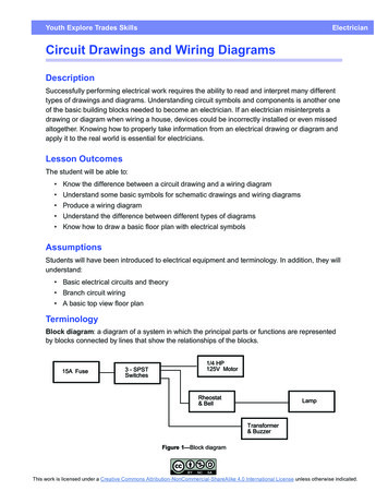
Standard Elementary Diagram SymbolsThe diagram symbols in Table 1 are used by Square D and, where applicable, conform to NEMA (National Electrical Manufacturers Association)standards.Table 1Standard Elementary Diagram SymbolsSWITCHESDisconnectCircuit InterrupterSELECTORSCircuit Breakersw/ Thermal OLCircuit Breakersw/ Magnetic OL2-Position Selector SwitchJKA1A2JKA1A2Pressure &Vacuum SwitchesN.O.N.C.Liquid Level SwitchesN.O.TemperatureActuated SwitchesN.O.N.C.N.C.3-Position Selector SwitchKLJA1A2JLimit SwitchesN.O.Speed (Plugging)N.C.FFAnti-PlugA1FA2KL2-Position Selector Push ButtonHeld ClosedAHeld OpenRFlow SwitchesN.O.N.C.RN.O.1234SelectorPositionFoot SwitchesAN.C.BBPushButtonContacts1-2 3-4FreeDepressedFreeDepressed contact closedPUSH BUTTONS – MOMENTARY CONTACTN.O.N.C.N.O. & N.C.(double circuit)MushroomHeadWobbleStickPUSH BUTTONS – MAINTAINEDCONTACT2 SingleCircuitsIlluminated1 DoubleCircuitRPILOT LIGHTSNon Push-to-TestINSTANT OPERATING CONTACTSPush-to-Testw/ BlowoutN.O.N.C.w/o BlowoutN.O.N.C.TIMED CONTACTSContact action retarded after coil C.T.C.G(indicate color by letter)1
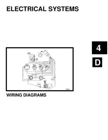
Standard Elementary Diagram SymbolsTable 1Standard Elementary Diagram Symbols (cont'd)TRANSFORMERSINDUCTORSIron CoreAutoAir CoreIron CoreAir CoreOVERLOAD RELAYSThermalCurrentDual VoltageAC MOTORSSingle PhaseMagnetic3-PhaseSquirrel Cage2-Phase, 4-WireWound RotorDC MOTORSArmatureShunt Field(show 4 loops)Series Field(show 3 loops)Commutating orCompensating Field(show 2 loops)WIRINGNot stable,by Fixed TapsRheostat,Potentiometer orAdjustable TapsRESHRESRESSEMICONDUCTORSDiode or HalfWave RectifierTunnelDiodeFull WaveRectifierNPNTransistorCAC DCZenerDiodeDCBBidirectionalBreakdown DiodeTriacPNPTransistorUJT,N BaseCSCRAC2PhotosensitiveCellGate Turn-OfThyristorAB2EGB1EUJT,P BaseB2EBPUTEB1K
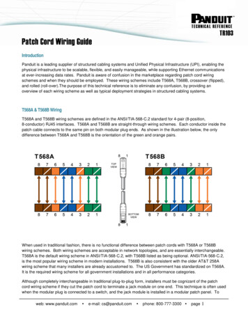
Standard Elementary Diagram SymbolsTable 1Standard Elementary Diagram Symbols (cont'd)OTHER COMPONENTSBellAnnunciatorBuzzerHorn, Alarm,Siren,etc.Meter (indicatetype by letters)VM Battery–FuseMeter ShuntThermocoupleSUPPLEMENTARY CONTACT SYMBOLSSPST, N.O.Single BreakDouble BreakSPST, N.C.Single BreakDouble BreakSPDTSingle BreakDouble BreakDPST, 2 N.O.Single BreakDouble BreakDPST, 2 N.C.Single BreakDouble BreakDPDTSingle BreakDouble BreakIEC SYMBOLSPush ButtonsN.C.N.O.CoilAux. ContactsN.O. N.C.ContactorBreakersSTATIC SWITCHING CONTROLLimit Switch, N.O., Static ControlStatic switching control is a method of switching electrical circuits without the use of contacts,primarily by solid state devices. To indicate static switching control, use the symbols shown in thistable, enclosing them in a diamond as shown.TERMSSPST:SPDT:DPST:DPDT:Single Pole, Single ThrowSingle Pole, Double ThrowDouble Pole, Single ThrowDouble Pole, Double ThrowN.O.:N.C.:T.O.:T.C.:Normally OpenNormally ClosedTimed OpenTimed ClosedPUT:SCR:Triac:UJT:Programmable Unijunction TransistorSilicon Controlled RectifierBidirectional Triode ThyristorUnijunction Transistor3
NEMA and IEC Markings and Schematic DiagramsControl and Power Connection TableTable 2NEMA and IEC Terminal MarkingsNEMAL1L2L3T1T2T3No standarddesignationNo specificmarkingAlphanumeric, correspondingto incoming line and motorterminal designationsControl TerminalsPower TerminalsCoil TerminalsIEC135246A114A1 A3A1 B1A2 B222Single digit numeric,odd for supply lines,even for load connections2-digit numeric, 1stdesignates sequence,2nd designates function(1-2 for N.C., 3-4 for N.O.)Power TerminalsControl TerminalsTable 3A1A2A2 sCoil TerminalsNEMA and IEC Controller Markings and Elementary ical Controller MarkingsTypical Elementary DiagramIECA11351321A2246142211 STOP 12 23 STARTTable 496Typical Elementary DiagramControl and Power Connections for Across-the-Line Starters, 600 V or less(From NEMA standard ICS 2-321A.60)Line MarkingsGround, when usedMotor RunningOvercurrent,units in:1 element2 element3 elementControl Circuit Connected toFor Reversing, InterchangeLines4A2 952423Typical Controller Markings24 A11-Phase2-Phase, 4-Wire3-PhaseL1, L2L1, L3: Phase 1L2, L4: Phase 2L1, L2, L3L1 is always ungrounded—L2L1———L1, L4———L1, L2, L3L1, L2L1, L3L1, L2—L1, L3L1, L3
TerminologyWIRING DIAGRAMA wiring diagram shows, as closely as possible, the actuallocation of all component parts of the device. The openterminals (marked by an open circle) and arrows representconnections made by the user.Since wiring connections and terminal markings areshown, this type of diagram is helpful when wiring thedevice or tracing wires when troubleshooting. Bold linesdenote the power circuit and thin lines are used to show thecontrol circuit. Black wires are conventionally used inpower circuits and red wire in control circuits for ACmagnetic equipment.A wiring diagram is limited in its ability to completely conveythe controller’s sequence of operation. The elementarydiagram is used where an illustration of the circuit in itssimplest form is desired.ELEMENTARY DIAGRAMAn elementary diagram is a simplified circuit illustration.Devices and components are not shown in their actualpositions. All control circuit components are shown asdirectly as possible, between a pair of vertical linesrepresenting the control power supply. Components arearranged to show the sequence of operation of the devicesand how the device operates. The effect of operatingvarious auxiliary contacts and control devices can bereadily seen. This helps in troubleshooting, particularly withthe more complex controllers.This form of electrical diagram is sometimes referred to asa “schematic” or “line” diagram.5
Examples of Control Circuits2- and 3-Wire ControlElementary DiagramsLow Voltage Release and Low Voltage Protection are the basic control circuits encountered in motor control applications. The simplest schemesare shown below. Other variations shown in this section may appear more complicated, but can always be resolved into these two basicschemes.Note: The control circuits shown in this section may not include overcurrent protective devices required by applicable electrical codes. See page11 for examples of control circuit overcurrent protective devices and their use.Low Voltage Release:2-Wire ControlFIG. 1Low Voltage Protection:3-Wire ControlL1L2M31FIG. 2OLL11L2STOPSTARTM32OLMPILOT DEVICE SUCH ASLIMIT SWITCH,PRESSURE SWITCH, ETC.Low voltage release is a 2-wire control scheme using amaintained contact pilot device in series with the starter coil.This scheme is used when a starter is required to functionautomatically without the attention of an operator. If a powerfailure occurs while the contacts of the pilot device are closed,the starter will drop out. When power is restored, the starterwill automatically pickup through the closed contacts of thepilot device.The term “2-wire” control is derived from the fact that in thebasic circuit, only two wires are required to connect the pilotdevice to the starter.Low voltage protection is a 3-wire control scheme usingmomentary contact push buttons or similar pilot devices toenergize the starter coil.This scheme is designed to prevent the unexpected starting ofmotors, which could result in injury to machine operators ordamage to the driven machinery. The starter is energized bypressing the Start button. An auxiliary holding circuit contact onthe starter forms a parallel circuit around the Start buttoncontacts, holding the starter in after the button is released. If apower failure occurs, the starter will drop out and will open theholding circuit contact. When power is restored, the Start buttonmust be operated again before the motor will restart.The term “3-wire” control is derived from the fact that in thebasic circuit, at least three wires are required to connect thepilot devices to the starter.2-Wire Control:Maintained Contact Hand-OFF-Auto Selector SwitchFIG. 3L1L2A1A23-Wire Control:Momentary Contact Multiple Push Button StationFIG. 4L1L2STARTIIHAND OFF AUTOA13AMOL1 STOP STOP STOPSTART2M3OLSTART1A2AA2M2-WIRE CONTROL DEVICEA Hand-Off-Auto selector switch is used on 2-wire controlapplications where it is desirable to operate the starter manuallyas well as automatically. The starter coil is manually energizedwhen the switch is turned to the Hand position and isautomatically energized by the pilot device when the switch isin the Auto position.6When a motor must be started and stopped from more than onelocation, any number of Start and Stop push buttons may bewired together. It is also possible to use only one Start-Stopstation and have several Stop buttons at different locations toserve as an emergency stop.
Examples of Control Circuits3-Wire ControlElementary Diagrams3-Wire Control:Pilot Light Indicates when Motor is RunningFIG. 1L113-Wire Control:Pilot Light Indicates when Motor is StoppedL2STOPSTARTM32FIG. 2L1OLL21STOPSTART32MOLMMMRGA pilot light can be wired in parallel with the starter coil toindicate when the starter is energized, indicating the motor isrunning.3-Wire Control:Push-to-Test Pilot Light Indicates when Motor isRunningFIG. 3L11L2STOPSTARTM32A pilot light may be required to indicate when the motor isstopped. This can be implemented by wiring a normally-closedauxiliary contact on the starter in series with the pilot light, asshown above. When the starter is deenergized, the pilot lightilluminates. When the starter picks up, the auxiliary contactopens, turning off the light.3-Wire Control:Illuminated Push Button Indicates when Motor isRunningFIG. 4L1OLL21STOP2START*3MOLMMRTESTR** Pushing on pilot light operates Start contacts.When the Motor Running pilot light is not lit, there may be doubtas to whether the circuit is open or whether the pilot light bulbis burned out. To test the bulb, push the color cap of the Pushto-Test pilot light.3-Wire Control:Fused Control Circuit Transformer and Control Relay3-Wire Control:Fused Control Circuit TransformerFIG. 5The illuminated push button combines a Start button and pilotlight in one unit. Pressing the pilot light lens operates the Startcontacts. Space is saved by using a two-unit push buttonstation instead of three.L1L2FIG. 6L1L2CRFU2FU1STARTSTOPMMOLSTARTMSTOPGROUND(If used)CROLMGROUND(If used)As an operator safety precaution, a step-down transformer canbe used to provide a control circuit voltage lower than linevoltage. The diagram above shows one way to provideovercurrent protection for control circuits.A starter coil with a high VA rating may require a control transformer of considerable size. A control relay and a transformer with a lowVA rating can be connected so the normally-open relay contactcontrols the starter coil on the primary or line side. Square D Size 5Combination Starter Form F4T starters use this scheme.7
Examples of Control Circuits3-Wire ControlElementary DiagramsJogging: Selector Switch and Start Push ButtonFIG. 1Jogging: Selector Push ButtonFIG. 2FPO 7-2FPO 7-1Jogging, or inching, is defined by NEMA as the momentaryoperation of a motor from rest for the purpose of accomplishingsmall movements of the driven machine. One method of joggingis shown above. The selector switch disconnects the holdingcircuit contact and jogging may be accomplished by pressing theStart push button.A selector push button may be used to obtain jogging, as shownabove. In the Run position, the selector-push button providesnormal 3-wire control. In the Jog position, the holding circuit isbroken and jogging is accomplished by depressing thepush button.Jogging: Control RelayJogging: Control Relay for Reversing StarterFIG. 3FIG. 4FPO 7-4FPO 7-3When the Start push button is pressed, the control relay isenergized, which in turn energizes the starter coil. The normallyopen starter auxiliary contact and relay contact then form aholding circuit around the Start push button. When the Jog pushbutton is pressed, the starter coil is energized (independent of therelay) and no holding circuit forms, thus jogging can be obtained.This control scheme permits jogging the motor either in theforward or reverse direction, whether the motor is at standstill orrotating. Pressing the Start-Forward or Start-Reverse push buttonenergizes the corresponding starter coil, which closes the circuitto the control relay.The relay picks up and completes the holdingcircuit around the Start button. As long as the relay is energized,either the forward or reverse contactor remains energized.Pressing either Jog push button will deenergize the relay,releasing the closed contactor. Further pressing of the Jog buttonpermits jogging in the desired direction.3-Wire Control:More than 1 Starter, 1 Push Button Station Controls all3-Wire Control:Reversing StarterFIG. 5FIG. 6FPO 7-5When one Start-Stop station is required to control more than onestarter, the scheme above can be used. A maintained overload onany one of the motors will drop out all three starters.8FPO 7-63-wire control of a reversing starter can be implemented with aForward-Reverse-Stop push button station as shown above. Limitswitches may be added to stop the motor at a certain point in eitherdirection. Jumpers 6 to 3 and 7 to 5 must then be removed.
Examples of Control Circuits3-Wire ControlElementary Diagrams3-Wire Control:Reversing Starter Multiple Push Button Station3-Wire Control: Reversing Starter w/ Pilot Lights toIndicate Motor DirectionFIG. 2FIG. 1More than one Forward-Reverse-Stop push button station may berequired and can be connected in the manner shown above.3-Wire Control:2-Speed StarterPilot lights may be connected in parallel with the forward andreverse contactor coils, indicating which contactor is energizedand thus which direction the motor is running.3-Wire Control: 2-Speed Starter w/ 1 Pilot Light toIndicate Motor Operation at Each SpeedFIG. 4FIG. 33-wire control of a 2-speed starter with a High-Low-Stop push buttonstation is shown above. This scheme allows the operator to start themotor from rest at either speed or to change from low to high speed.The Stop button must be operated before it is possible to change fromhigh to low speed. This arrangement is intended to prevent excessiveline current and shock to motor and driven machinery, which resultswhen motors running at high speed are reconnected for a lower speed.One pilot light may be used to indicate operation at both low andhigh speeds. One extra normally-open auxiliary contact on eachcontactor is required. Two pilot lights, one for each speed, maybe used by connecting pilot lights in parallel with high and lowcoils (see reversing starter diagram above).Plugging:Plugging a Motor to a Stop from 1 Direction OnlyAnti-Plugging:Motor to be Reversed but Must Not be PluggedFIG. 5Plugging is defined by NEMA as a braking system in which the motorconnections are reversed so the motor develops a counter torque, thusexerting a retarding force. In the above scheme, forward rotation of themotor closes the normally-open plugging switch contact andenergizing control relay CR. When the Stop push button is operated,the forward contactor drops out, the reverse contactor is energizedthrough the plugging switch, control relay contact and normally-closedforward auxiliary contact. This reverses the motor connections and themotor is braked to a stop. The plugging switch then opens anddisconnects the reverse contactor. The control relay also drops out.The control relay makes it impossible for the motor to be plugged inreverse by rotating the motor rotor closing the plugging switch. Thistype of control is not used for running in reverse.FIG. 6Anti-plugging protection is defined by NEMA as the effect of adevice that operates to prevent application of counter-torque bythe motor until the motor speed has been reduced to anacceptable value. In the scheme above, with the motor operatingin one direction, a contact on the anti-plugging switch opens thecontrol circuit of the contactor used for the opposite direction.This contact will not close until the motor has slowed down, afterwhich the other contactor can be energized.9
Examples of Control CircuitsShunting Thermal Units During Starting PeriodElementary DiagramsShunting Thermal Units During Starting PeriodFIG. 1Article 430-35 of the NEC describes circumstances underwhich it is acceptable to shunt thermal units duringabnormally long accelerating periods.430-35. Shunting During Starting Period.(a) Nonautomatically Started. For a nonautomaticallystarted motor, the overload protection shall bepermitted to be shunted or cut out of the circuit duringthe starting period of the motor if the device by whichthe overload protection is shunted or cut out cannot beleft in the starting position and if fuses or inverse timecircuit breakers rated or set at not over 400 percent ofthe full-load current of the motor are so located in thecircuit as to be operative during the starting period ofthe motor.FPO 9-1(b) Automatically Started. The motor overload protectionshall not be shunted or cut out during the startingperiod if the motor is automatically started.Exception. The motor overload protection shall bepermitted to be shunted or cut out during the starting periodon an automatically started motor where:(1) The motor starting period exceeds the time delayof available motor overload protective devices, and(2) Listed means are provided to:a. Sense motor rotation and to automaticallyprevent the shunting or cut out in the eventthat the motor fails to start, andb. Limit the time of overload protection shuntingor cut out to less than the locked rotor timerating of the protected motor, andc. Provide for shutdown and manual restart ifmotor running condition is not reached.Figures 1 and 2 show possible circuits for use inconjunction with 3-wire control schemes. Figure 1 complieswith NEC requirements. Figure 2 exceeds NECrequirements, but the additional safety provided by the zerospeed switch might be desirable.Figure 3 shows a circuit for use with a 2-wire, automaticallystarted control scheme that complies with NECrequirements. UL or other listed devices must be used inthis arrangement.FIG. 2FPO 9-2FIG. 3FPO 9-310
Examples of Control CircuitsOvercurrent Protection for 3-Wire Control CircuitsElementary Diagrams3-Wire Control:Fusing in 1 Line OnlyFIG. 13-Wire Control:Fusing in Both LinesL1L2FIG. 2L1FU1FU2FU1STARTSTOPMOLMSTARTSTOP3-Wire Control:Fusing in Both Primary and Secondary LinesL1L2FIG. PX2MOLMControl circuit transformer with fusing in both primary lines, nosecondary fusing and all lines ungrounded.Control circuit transformer with fusing in both primary lines andboth secondary lines, with all lines ungrounded.3-Wire Control:Fusing in Both Primary Lines and 1 Secondary LineL1L2FU1SECSTARTMFIG. 5OLCommon control with fusing in both lines and with both linesungrounded.3-Wire Control:Fusing in Both Primary LinesFU1MMGNDCommon control with fusing in one line only and with both linesungrounded or, if user’s conditions permit, with one line grounded.FIG. 3L23-Wire Control:Fusing in Both Primary and Secondary LinesFor Large Starters using Small TransformerFIG. GNDSTOPSECSTARTX2CROLMControl circuit transformer with fusing in one secondary line andboth primary lines, with one line grounded.Control circuit transformer with fusing in both primary lines andboth secondary lines, with all lines ungrounded. Used for large VAcoils only.11
AC Manual Starters and Manual Motor Starting SwitchesClass 2510Manual Motor Starting Switches:Class 2510 Type KFIG. 1T1FIG. 2L1T1L1L1T2T3L2L3T3L2T1L3PILOTLIGHT(IF USED)RPILOTLIGHT(IF USED)RT3T1 T2 T3MOTORMOTOR2-Pole, 1-Phase3-Pole, 3-PhaseFractional Horsepower Manual Starters:Class 2510 Type FFIG. 3FIG. 4T2FIG. 5T2L2L2L1L1T2AOHRT1T1PILOTLIGHT(IF USED)PILOTLIGHT(IF USED)RT1T2T1MOTOR2 1L14 3PILOTLIGHT(IF USED)RT1T22MOTOR1-PoleL2A O H42-WIRECONTROLDEVICE2-PoleT24MOTOR2-Pole w/ Selector SwitchIntegral Horsepower Manual Starters:Class 2510 Size M0 and M1FIG. 6L1L2FIG. 7L1L2T2FIG. 8L1L2FIG. 9L1L2L3T1T2T3FIG. 10L1L2L3T1T2T3L2L3L1T1T2T1T1T2T1T2T1MOTORT2T1T3T1 T2 T3T1 T2 T3MOTORMOTORT3MOTORMOTOR2-Pole, 1-Phase3-Pole, DC3-Pole, 1-Phase3-Pole, 3-Phase3-Pole, 3-Phase w/ additionalInterlock (Form X) 12
AC Manual Starters and Manual Motor Starting SwitchesClass 2511 and 2512AC Reversing Manual Starters and Manual Motor Starting Switches:Class 2511FIG. 1FIG. 2REVFWDT1L1T2L2T3L3L1L2L3T1T2T3T1 T2 T3T1 T2 T3MOTORMOTORReversing Manual Motor Starting SwitchType K, 3-Pole, 3-PhaseReversing Manual StarterSizes M0 and M1, 3-Pole, 3-PhaseAC 2-Speed Manual Motor Starting Switches:Class 2512 Type KFIG. 4FIG. 3FPO12-6bFPO12-6a2-Pole, 1-Phase w/ Pilot Lights3-Pole, 3-PhaseAC 2-Speed Manual Motor Starters:Class 2512 Type FFIG. 5FIG. 6FPO13-1a2-Unit, 2-Pole w/ Mechanical Interlock and Pilot LightsFPO 13-1b3-Unit, 2-Pole w/ Selector Switch and Pilot Lights 13
2-Speed AC Manual Starters and IEC Motor ProtectorsClass 2512 and 2520 and Telemecanique GV1/GV32-Speed AC Manual Motor Starters:Class 2512 Size M0 and M1FIG. 1L1L2L3T2 T11 T13T1 T3 T12MOTORT1T2T3T11T12T132-Speed Manual Starter for Wye-Connected, Separate Winding MotorMotor Protective Switches:Class 2520FIG. 21/L13/L2FIG. 35/L31/L13/L25/L3FIG. 41/L13/L25/L32/T1 4/T2 6/T32/T1 4/T2 6/T32/T1 4/T2 6/T3T1 T2 T3T1T3T3MOTORMOTORMOTOR3-Pole, 3-Phase2-Pole Application1-Pole ApplicationIEC Manual Starters:GV1/GV3FIG. 51/L1 3/L25/L3FIG. 6FIG. 7GV3 B D1I I I 2/T1 4/T2 6/T3GV3 A0895D2GV3 D C1GV3 M Motor ProtectorFIG. 8 GV3 A099796I 98GV3 A0 Fault Signalling ContactsGV1 A021321132314221424GV1 A0313 23 31GV1 A0513 23 3314 24 3214 24 34GV1 A06C2I GV1 A01GV3 Voltage TripsGV1 A0713 23 3313 23 3114 24 3414 24 33GV1 A0 Contact Block 14
Drum SwitchesClass 2601Drum Switches:Class 2601REVERSEOFFMOTORFORWARD12 121234 343456 5656123456DRUM SW.MOTOR123456MOTORDRUM SW.FIG. 3MOTORDRUM SW.123456LINE1-Phase, Capacitor or Split-Phase MotorFIG. 5LINEMOTOR1-Phase, 4-Lead Repulsion Induction MotorFIG. 6LINE3-Phase, 3-Wire MotorInternal SwitchingFIG. 4DRUM SW.STARTFIG. 2HANDLE ENDRUNFIG. 1DRUM SW.123456LINE1-Phase, 3-Lead Repulsion Induction MotorFIG. 7LINEDRUM SW. LINEMOTOR121234345656COMMON2-Phase, 4-Wire MotorMOTORLINE123456DC, Shunt MotorDRUM SW.12ARMATURE3456DC, Series MotorLINEFIG. 10MOTORDRUM SW.LINE12ARMATURESERIESFIELDDRUM SW.SERIESFIELDARMATURESHUNT FIELDMOTORFIG. 9SHUNT FIELD2-Phase, 3-Wire MotorFIG. 83456DC, Compound Motor 15
DC Starters, Constant and Adjustable SpeedClass 7135 and 7136Constant Speed DC Starter: Class 7135FIG. 1FPO 15-1Typical Elementary Diagram forNEMA Size 2
Wiring Diagram Book A1 15 B1 B2 16 18 B3 A2 B1 B3 15 Supply voltage 16 18 L M H 2 Levels B2 L1 F U 1 460 V F U 2 L2 L3 GND H1 H3 H2 H4 F U 3 X1A F U 4 F U 5 X2A R Power On Optional X1 X2115 V . Static switching control is a method of switching electrical circuits without the use of contacts, primarily by solid state devices. To indicate .File Size: 2MB