Transcription
A P P L I C A T I O N SG U I D EVoice EvacuationSystems
A P P L I C AT I O N SG U I D E :V O I C EE VA C U AT I O NS Y S T E M SVoice EvacuationSystemsContentsSection 1: Introduction. 3Factors that are controllable by a voice evacuation system designer. 8What is the driving factor for voice evacuation systems?. 3Signal-to-noise ratio. 8Section 2: Basics of Sound. 3Speaker Frequency Response . 7What is sound?. 3Total harmonic distortion. 7How does sound travel?. 3Speaker Placement. 8Section 3: Measuring Sound Output. 3Voltage drop on speaker circuits. 8Sound Pressure Level (SPL). 3Factors that are not controllable by a system designer. 8Decibel. 4Room acoustics. 8A-Weighted Scale. 4Countering the effects of reverberation. 9B-Weighted Scale. 4Section 8: Testing for Intelligibility. 9C-Weighted Scale. 4Measurement Methods. 9Adding SPL from two speakers. 4Intelligibility Measurement Methods. 9dB Rules of Thumb. 4Quantitive Method Tips and Tricks. 9Section 4: Basics of Speaker Operation. 5Testing Methods: When and Where. 9Cone Materials. 5Use of Intelligibility Meters. 9High Impedance (70.7 Volt/25 Volt) Distributed Line Systems. 5Direct injection method for test signal. 10Section 5: Basics of Voice Evacuation System Amplifiers. 5Calibrating Signal Source. 10Section 6: Laws, Codes and StandardsRelevant to Voice Evacuation Systems. 5Method 1. 10Accessibility Guidelines. 5Anechoic vs. Reverberant Chamber. 5International Building Code & International Fire Code. 6NFPA 72 , The National Fire Alarm and Signaling Code. 6Audibility Requirements Per NFPA 72. 6ANSI/UL 1480 and CAN/ULC-S541. 6Section 7: Designing for Intelligibility. 7Definition. 7How to Layout Voice System. 72Method 2. 10STI/STIPA Test Procedure. 10Occupied Testing. 10Unoccupied Testing. 10Acceptable Criteria. 10Limitations of Test Methods. 11Section 9: Glossary of Terms.11Section 10: References. 12
S Y S T E MSection 1:S E N S O RSection 2:IntroductionBasics of SoundThe purpose of this guide is to provide information about voice alarm systems used in conjunction with fire alarm and emergency communicationsystems. Voice communications are extensively used to provide building occupant notification during emergencies. These messages containvital safety information that must be clearly understood by the buildingoccupants.What is sound?Sound is created by mechanical vibrations that displace air molecules tocreate repetitive changes in air pressure. The ear detects these changes inair pressure and perceives the magnitude as loudness and the frequencyas pitch.While the information in this guide is based on years of industry experience, The standard ear can hear from a wide range of 20 Hz through 20,000 Hz.it is intended to be used only as a guide. The requirements of applicable Table 1.codes and standards, as well as directives of the authority having jurisdiction (AHJ) should be followed. In particular, the most current version ofNFPA 72 , National Fire Alarm and Signaling Code , now requires thatYoung childrenup to 25Khzemergency voice/alarm communications systems be intelligible and discusses methods for verifying intelligibility.13 years and upup to 20KHzThis guide provides general information on the concepts of intelligibilityand the design of emergency voice/alarm communications systems. It isintended to provide a better understanding of the factors affecting the intelligibility of these systems in public spaces, in order to improve design ofsystems that meet the requirements for speech audibility and intelligibilityin a cost-effective manner.Adultsup to 16KHzElderly adultsdepends on lifetime noise exposureSpeech frequencies range from 500Hz to 4,000 HzHow does sound travel?What is the driving factor for voice evacuation systems?The air molecules themselves don’t move very far. They simply transfer pressure changes into sound waves. Sound waves move away from the soundIntelligibility for mass notification systems had its inception with the source, such as a speaker, at a speed determined by the sound source.Department of Defense Unified Facilities Criteria (UFC) document 4-021- The more power the source emits, the wider the sound waves spread. In01, the Design and O&M: Mass Notification Systems.addition, the further out the sound waves travel from the source, the lessintense they become.Voice evacuation systems are growing in popularity and, required in moreareas. The events of September 11, 2001, were a main driver because they Sound waves are regularly intercepted by other sound waves. Imaginehighlighted the need to communicate to a large group of individuals out- two children jumping into the water at the same time: their waves overlap.side of a fire event. That is especially critical for buildings where you have Similarly, when a sound wave is intercepted by an outside force, a portionto manage the evacuation of complex layouts, such as high-rise buildings is reflected into a different direction. As a result, before installing a voiceor large areas of assembly.evacuation system, it’s imperative to understand sound output and the waysound waves reflect and interact.Prior to these emergency events, voice systems would only be used periodically during fire drills. Due to the need for constant communication, design Section 3:importance and voice message intelligibility are critical.Measuring Sound OutputAlthough it’s necessary to communicate with occupants regarding a multitude of emergencies, such as weather threats or toxic gases, a traditionalevacuation tone may not be an ideal signal for non-fire events where seeking shelter is preferred to evacuation.States are also moving to the latest editions of the National Fire AlarmSignaling Code and building codes, which require voice systems in certain occupancies.Basic components should be reviewed in order to understand voicesystems.3Sound Pressure Level (SPL)SPL is the difference between the pressure produced by a sound waveand the ambient pressure at some point in space. Sometimes SPL is confused with loudness of sound, but in reality SPL is a contributing factor ofloudness but not loudness itself. The SPL range for the human ear is from0 to 120 decibels. Going louder, the human threshold of pain is 130 decibels. Eardrums rupture at 190 decibels.
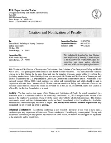
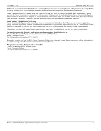
A P P L I C AT I O N SG U I D E :V O I C EE VA C U AT I O NSP1 80dBSP2 80dBDecibelAudio levels are commonly used by engineers using “Decibels” (dB) toexpress ratios between levels, such as power, Volts, Amps, and SoundPressure Levels (SPL). The decibel is not an absolute measure like Voltsand Amps; rather, it is used to make comparisons between two numbers.The decibel is defined as the logarithm of two power levels, shown belowin the equation as P1 and P0:Decibel 10 logReference P0 1pW 10-12WdB 10log(P/P0)80 10log(P/10-12)P1P0P0 is the reference power (P0 1pW 10-12W) and P1 is the power levelused for comparison. The logarithm is used in the decibel in order to makecomparisons of power over a very wide range. This is very useful in audioapplications as the ear responds logarithmically to changes in SPL.8 log(P/10-12)10 8 (P/10-12)P (108)(10-12) (10-4) .0001W2P 2*.0001W .0002WdB 10log((.0002/10-12)) 83When the decibel is used to express SPL, the reference sound pressureis 20 x 10-6 Newtons/m² which is the approximate hearing threshold for anormal listener. When using a dB meter to measure sound, the meter is performing the calculation between the received SPL and the reference SPL:dBspl 20logSPL20 x 10-6S Y S T E M SOnline tools for SPL addition can simplify this process. If the two dB levels are identical, then simply add 3 dB to either one. If the SPL from onespeaker is more than 10 dB higher than the other, then simply use thehigher SPL value.A-Weighted ScaledB Rules of ThumbAn A-weighting filter is sometimes used when measuring SPL with frequencies around 600- 7,000 Hz. Because speech frequencies range from 500to 4,000 Hz, the filter ensures that the measured dB corresponds with perceived loudness. In other words, the filter desensitizes the sound level meterto the extreme high and low frequencies. These sound levels are still measured in decibels, but are symbolized by dBA.Sound pressure levels drop approximately 6 dB for every doubling of distance and increase by 3 dB for every doubling of power. For example,take a one watt speaker that provides 85 dBA at 10 feet. At two watts, thespeaker will provide 88 dBA at 10 feet and 82 dBA at 20 feet. This ruleof thumb is important to remember when determining whether you needfewer high powered centralized speakers or more low-powered dispersedspeakers.B-Weighted Scale85 dBAA B-weighting scale is sometimes used when measuring SPL with frequencies around 300- 4,000 Hz.1W10ftC-Weighted Scale88 dBA2WAn C-weighting filter is sometimes used when measuring SPL with frequencies around 70Hz-4,000 Hz.A-weighted scale is referenced in most test and building standards butthe C-weighted scale is useful for measuring the peaks of the noise levels.10ft82 dBA2W20ftAdding SPL from two speakersIf there is an application with two speakers in close proximity, the soundfrom the speakers is additive. However, the dB levels cannot simply beadded together to determine the sound level. Instead, the SPLs have tobe converted back to their actual powers and then added them to recalculate the level in dB. For example, one 80 dB speaker plus a second 80dB speaker doesn’t equal 160 dB.4Figure 1. dB Rules of Thumb
S Y S T E MSection 4:Basics of Speaker OperationCone MaterialsThe cone, the part of the speaker that physically moves the air molecules,comes in a variety of materials, including paper, polypropylene, andcarbon fiber.Paper is the conventional material for speaker cones because it is easyto form into a variety of shapes. However, the paper must be chemicallycoated to adjust to changes in humidity and temperature. As humidityincreases, the percentage of moisture within the paper increases. Thisleads to changes in cone mass and other parameters. Despite this, a wellengineered paper cone can still deliver frequency response as smooth asany high technology material.S E N S O ROther standard amplifier features are field-adjustable voltage (25 or 70.7volts); built-in alert tone generators with steady, 520 Hz square wave, slowwhoop, high/low or chime capabilities; field-selectable tones; speaker zonecontrol; independently field-programmable input circuits; power-limitedoutputs; aux
speaker systems would simply not be practical over long wire distances because of the voltage drop. As a result, a system was developed that pro - duced near constant voltage to all of the speakers in the system. Constant voltage fire alarm voice evacuation speaker systems in the United States require 70.7 volt or 25 volt, also known as 70 volt and 25 volt systems. These systems not only .