Transcription
I.Damage-Mitigati ng Controlof Aircraft for Enhanced Structural D urab iIityJEFFREY CAPLINASOK RAY, Senior Member, IEEEThe Pennsylvania State UniversitySURESH M. JOSM, Fellow, IEEENASA Langley Research CenterThe concept and a design methodology for robustdamage-mitigating control (DMC) of aircraft is presented. Thegoal of DMC is to simultaneously achieve high performanceand structural durability and the design procedure is based ondamage mitigation at critical structures and retention of theflight performance. An aeroelastic model of the wings has heenformulated and is incorporated into a nonlinear rigid-body modelof aircraft flight-dynamics. Robust damage-mitigating controllersare then designed using the &-based structured singular value( p ) synthesis method based on a linearized model of the aircraft.In addition to penalizing the error between the ideal performanceand the actual performance of the aircraft, frequency-dependentweights are placed on the strain amplitude at the root of eachwing. Using each controller in turn, the control system is putthrough an identical sequence of maneuvers, and the resulting(varying amplitude cyclic) stress profiles are analyzed usinga fatigue crack growth model that incorporates the effects ofvarying-amplitude cyclic loading. Comparisons are made todetermine the impact of different strain-amplitude weights onthe resulting flight performance and fatigue crack damage inthe wings. The results of simulation experiments show signiEcantsavings in fatigue life of the wings while retaining the dynamicperformance of the aircraft.Manuscript received March 24, 1999; revised April 25, 2000;released for publication January 22, 2001.IEEE Log NO. T-AES137/3/08.557.Refereeing of this contribution was handled by W. D.Blair.The research work reported in this paper has been supported in partby NASA Langley Research Center under Grant No. NCC-1-249,National Science Foundation under Grant No. CMS-98 19074, andNational Academy of Sciences under a Research Fellowship awardto A. Ray.iAuthors’ addresses: J. Caplin and A. Ray, Mechanical EngineeringDepartment, The Pennsylvania State University, University Park,PA 16802, E-mail: (axr2Opsu.edu); S . M. Joshi, NASA LangleyResearch Center, Hampton, VA 23681-0001.0018-92511011 10.00 @ 2001 IEEEINTRODUCTIONDesigners of flight control systems haverecognized the possibility of actively reducing damagein certain aircraft structures, particularly the wing.The simplest concept that is currently employedon both F-16 and F/A-18 aircraft is the so-called“g-limiter.” It serves to limit the aircraft’s maximumload factor to a predefined value. Transport aircrafthave used the gust load alleviation (GLA) system[6, 191 that uses feedback from accelerometers onthe wing to drive special control surfaces in order toreduce the additional loads imposed by atmosphericdisturbances. A similar concept, known as maneuverload alleviation (MLA) [20] or maneuver load control(MLC) [30], has been proposed for high-performanceaircraft. The aim of these systems is to shift the liftdistribution inboard during high loading conditions tolimit the bending moment at the wing root. Dynamicstresses have been considered in the so-called fatiguereduction (FR) system [20] that seeks to minimize theamplitude and/or number of stress cycles experiencedat the critical point(s). While these systems haveshown tangible benefits, there is apparently a commonweakness that may well prevent them from achievingtheir maximum potential. In all cases, the actualdynamics of the fatigue crack damage phenomenon inthe structural material are not included in the analysis.It is simply assumed that, by limiting the peak stressat the critical points of the structure, life-savings aremaximized. Since transient stress overloads couldresult in retardation of crack growth [3, 231, thefrequency content of the applied stresses could beshaped by control actions to achieve larger fatigue lifethan the traditional approach of simply limiting thepeak stress.From an economic standpoint it is desirable toobtain the maximum amount of useful life from themost expensive (and hard to replace) componentsof the aircraft, as well as to reduce the number ofmaintenance inspections required to ensure structuralintegrity of critical components. This practice isalso desirable from an operational viewpoint, sincereductions in downtime for inspection and repairresult in increased availability. However, sincefailure of certain components may result in loss ofthe aircraft, and more importantly, loss of humanlife, safety considerations mandate replacement ofall critical components before a failure is likely tooccur. This requirement is realized in the following’way. A fighter aircraft that exceeds its design loadfactor during a flight is temporarily removed fromservice, and it must undergo a rigorous inspection todetermine if any special maintenance is required priorto its return to flying status.This paper addresses the above issue focusingon fatigue damage mitigation in the wingsof high-performance aircraft that are usuallyIEEE TRANSACTIONS ON AEROSPACE AND ELECTRONIC SYSTEMS VOL. 37, NO. 3 JULY 2001849
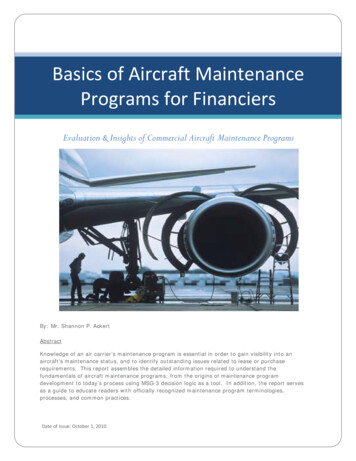
instrumented for health monitoring and control. Thethrust of the paper is on robust damage-mitigatingcontrol (DMC) where the goal is to achieve largegains in structural durability by manipulation ofstress profiles with no significant loss of performance[25]. This concept of DMC has been investigatedfor reusable rocket engines [lo, 151, rotorcraft[26, 271, and fossil fuel power plants [17]. In allcases, simulation results show a substantial increasein component life with no significant loss in systemperformance. Efficacy of the DMC concept has alsobeen demonstrated by laboratory experimentation on atest apparatus [32].The paper is organized in five sections includingthe introduction. Section I1 describes modelformulation for damage mitigating controller design.Section I11 presents a procedure for synthesis of therobust DMC law. Section IV presents the overallsimulation structure and the results of the aircraftperformance and crack-growth damage for a familyof robust controllers. Section V summarizes andconcludes with recommendations for future work.II. MODEL FORMULATION FOR DAMAGEMITIGATING CONTROLLER DESIGNAlthough it has long been recognized thatcontroller design for highly flexible aircraft, such astransports, requires dynamic models that explicitlyinclude structural flexibility [20], these effects areoften ignored on aircraft that experience relativelysmall elastic deformation. This is particularly truewhen modern robust control techniques, such asH,-synthesis, are employed, since the effects ofunmodeled dynamics due to flexibility can beincluded within the (unstructured) uncertainty model.However, explicit modeling of structural flexibilitymay provide a solution to another problem facedby flight control systems designers, namely that ofcontrol surface redundancy. High-performance aircraftrequire two (or more) different sets of control surfacesfor roll control and, in some cases, have multiplecontrols for pitch and yaw as well. As these controlshave different levels of effectiveness at different flightconditions, they appear to be redundhnt actuators inthe controller synthesis process at a given operatingcondition . Therefore, special measures are requiredto allocate commands between the various controlsurfaces. Methods that have been developed to dateinclude the use of a nonlinear control selector [8], orthe use of off-line constrained optimization procedures[ 131. In both cases, the methods only examine theeffects of the controls on the rigid-body motion ofthe aircraft. The DMC takes advantage of the controlsurface redundancy by utilizing the elastic behavior ofthe aircraft structure as well as the rigid-body motion.The theme of DMC design is that different locationsof control surfaces on the airframe may result in850different effects on the elastic modes of the aircraftstructure. Thus, the control systems designer can makeuse of all available control surfaces to simultaneouslyachieve the desired level of performance whilemitigating the structural damage by reshaping thestress profile.So far the only application of DMC to aviationsystems has been the work of Rozak and Ray [26,27]who developed a robust controller for rotorcraftwith the objective of reducing damage to the controlhorn of the main rotor. Since the control horn doesnot directly experience any significant aerodynamicforces, the loading is of a purely mechanical nature.In contrast, the loads (and hence stresses) acting onan aircraft wing occur due to aeroelasticity, whichdeals with interactions of aerodynamic forces withflexible structures. The aerodynamic forces playa dominant role in determining the dynamics ofthe aircraft that, in turn, lead to deformations andstresses in the critical structures. Therefore, changesin aerodynamic forces due to structural deformationhave been included in the plant dynamic model incombination with the rigid-body model.A.Rigid-Body ModelThe rigid-body flight dynamic model used here issimilar to the corresponding model developed for theAIAA Controls Design Challenge [7] and thereforethese model equations are not repeated here. Thecontrol surfaces include left and right ailerons, leftand right stabilators, and a single rudder. Although theaircraft has five control surfaces, only four variablesare required to specify their positions: the ailerondeflection SA, the rudder deflection S, the symmetricstabilator deflection 6, and the differential stabilatordeflection 6,. The positions of the individual controlsurfaces are determined as follows:left aileron position 0.56,right aileron position -0.56,left stabilator position 6, 0.56,right stabilator position 6, - 0.56,rudder position 6,.In the original model of Brumbaugh (1991), allactuator dynamics are represented as first order lagswith a time constant of 50 ms that has been replacedwith more detailed dynamics [l]. The transferfunctions and rate limits of the actuators are given inTable I.Linearization of the equations of motion for arigid, fixed-wing aircraft yields two uncoupled sets ofequations. One set govems the longitudinal dynamicsof the aircraft while the other govems the lateraldynamics. We have followed the standard practice todesign separate controllers for lateral and longitudinaldynamics based on the uncoupled linearized modelsEEE TRANSACTIONS ON AEROSPACE AND ELECIRONIC SYSTEMS VOL. 37. NO. 3 JULY 2001
TABLE IDynamic Models of ActuatorsControlSurfaceTransfer FunctionAileron1 .oDeflectionLimits (deg)1 .o2 x 0.69RudderStabilatorRate Limits. (deg/s)f20flOOf30flOO 15/-25f602 x 0.41and then evaluate the control system based on thesimulation of the nonlinear model.The stick-fixed longitudinal motion of a rigidaircraft disturbed from equilibrium flight is describedby two oscillatory modes of motion: the short periodmode and the long period (or phugoid) mode. Theshort period mode typically has a period on theorder of a few seconds, with motion characterized bychanges in angle of attack, pitch angle, and altitude,while the flight velocity remains practically constant.The phugoid mode has a much longer period, on theorder of tens or hundreds of seconds, with motioncharacterized by changes in velocity, pitch angle, andaltitude; with angle of attack remaining approximatelyconstant. Because of the slow dynamics associatedwith the phugoid mode, this mode has been ignoredduring the synthesis of the DMC laws for manualflight. The pitch rate q, and angle of attack (I! are thestate variables of interest for longitudinal rigid-bodymotion. However, for the design of an autopilot,the phugoid motion becomes the primary mode ofinterest.The desired short period response of the aircraft isthat of a second-order system. The natural frequencyis a function of the acceleration sensitivity of theaircraft, which is the change in load factor per unitchange in angle of attack. The acceleration sensitivityis determined by the aerodynamics of the aircraft andthe particular flight condition under consideration.Thus, the desired natural frequency also varies withdifferent flight conditions. The damping ratio of theshort period mode is required to be between 0.35 and1.3 for all flight conditions based on MIL-F-8785Cspecifications [ 111.The roll rate p , yaw rate r , and sideslip anglep are the state variables of interest for lateralrigid body motion. The stick-fixed lateral motionof a rigid aircraft is described by three naturalmodes: 1) the Dutch roll mode consisting of lightlydamped, oscillatory, out-of-phase roll, yaw, andsideslip motions; 2) the roll mode consisting of aI'nonoscillatory, highly convergent mode describingthe rolling characteristics of the aircraft; and 3) thespiral mode consisting of nonoscillatory, convergentor divergent motion following a sideslip disturbance.Note that an unstable spiral mode will cause theaircraft to go into a turn that becomes increasinglytighter with time. The handling qualities requirementsspecify that the Dutch roll mode should have afrequency of at least 1 rads. The damping ratio mustbe greater than or equal to 0.4, or the product ofthe frequency and damping ratio should be greaterthan or equal to 0.4 rads, whichever results in thelarger value for the required damping. The roll moderequirement states that the roll time constant mustbe less than or equal to 1.0 s. This requirement isactually conservative with regards to modem fighters,which typically have roll time constants in the rangeof 0.33 to 0.5 s [l]. The spiral mode requirementspecifies that the minimum time to reach a 40" bankangle following a 20" bank angle disturbance must begreater than or equal to 12 s. Because of the slowerdynamics of the spiral mode, it is typically ignoredduring controller synthesis.B.Atmospheric ModelAtmospheric properties are based on the USStandard Atmosphere (1962). The model outputsvalues for temperature, static pressure, density, andspeed of sound as functions of altitude. While notstrictly an atmospheric property, the model alsoincludes tabulated values for the acceleration due togravity, also as a function of altitude. The atmosphericmodel in this work is similar to the correspondingmodel developed for the AIAA Controls DesignChallenge [7] and is not repeated here.C.Aeroelastic ModelAerodynamic forces acting on a body depend onthe time history of the body's motion [14]. WhenCAPLIN ET AL.: DAMAGE-MITIGATING CONTROL OF AIRCRAFT FOR ENHANCED STRUCTURAL DURABILITY85 1
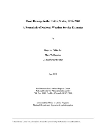
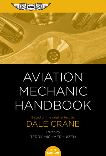
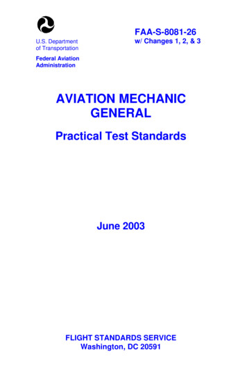
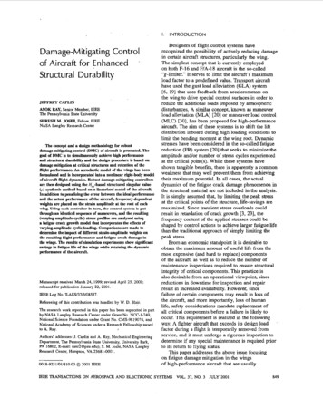
the dynamics of a rigid aircraft are the subject ofinterest, particularly if the aircraft does not performany severe maneuvers, the much faster dynamics ofthe flowfield are ignored based on the principle ofsingular perturbation. For aircraft that are requiredto perform extreme maneuvers, it is often sufficientto introduce approximate correction factors into theequations of motion to account for any unsteadyaerodynamic forces. These correction factors generallydepend on the time derivatives of angle of attack andsideslip angle. However, when the flexible structuresof aircraft (that have a faster time scale than therigid-body dynamics) are of interest, it becomesnecessary to explicitly model the dynamics of theflow-field to identify any potential instability due tofluid-structure interactions, known as flutter. Sincewing flutter results in catastrophic failure of theaircraft, it is prevented either through the design of thewing, or through the use of active flutter suppression(AFS). Therefore, an aeroelastic model of the criticalstructure (i.e., the wings) is required for the DMCdesign for the following reasons.1) To shape the profiles of transient stresses forfatigue damage reduction,2) To ensure that the control system does notadversely affect the flutter characteristics.1) Structural Model: Although composite wingstructures have been used in recent aircraft, mostfighter aircraft have wings that are at least partially,and in most cases solely, built from ductile alloys.A typical wing structure contains at least two sparsthat run the length of the wing semispan to bear themajority of the bending loads. The spars and theskin together form several torsion boxes to resisttwisting deformation of the wings. The wings alsocontain many lesser structural members whoseprimary function is to maintain the shape of the skin.The structural model is formulated here as a pair ofEuler beams to represent the important structuralbehavior of the wings. Each beam model is alignedwith the elastic axis (i.e., the line through which loadsapplied normal to the plane of the wing result in purebending). The center portion of the model, where thebeams meet, is assigned proportionately higher valuesof bending and torsional stiffness in order to representthe fuselage. The model is spatially discretized andcast in the finite element setting. While the detailsof the finite-element model, including the elementtype and shape functions, are reported by Caplin(1998), its basic features and dominant mode shapesare presented below.The generalized displacement vector t(t)isobtained by orthogonal transformation of the physicaldisplacement vector O(t), i.e., (t) @d(t) whereQ, is the orthogonal matrix whose columns are theindividual mode shapes. The governing equation for852Bpo.21I,I-nu-25-20 -15 -10,,,,,,20252025displacement fl)Angle of hvist Ideg)-505Wing Span (fl)1015c 0.0-.3n ‘u.6.4-0.6-25*--,OS,-20 -15I-10II/- 4-0.5-25-20 -15-10displacement fl)Angle of hvist {deg)-505Wing Span (fl)I.II1015IIIIdisplacement fl)Angle of twist [deg)-505Wing Span (fl)10152025Fig. 1. First three symmetric mode shapes.( ( t ) is obtained in the transformed coordinates asMi‘@) C i ( t ) K [ ( t ) f ( t )(1)where the transformed “modal mass” and “modalstiffness” matrices M and K are diagonal, C isthe “modal damping” matrix representing energydissipation, and f ( t ) the total generalized force vectorwhich is obtained by orthogonal transformation of theapplied nodal force vector that is a linear combinationof aerodynamic force due to both vibratory motion offlexible modes and rigid-body motion. Accordingly,the total generalized force vector is expressed asf (t f&(t) f”gid(t)(2)where faex is the generalized aerodynamic forcevector acting on the flexible modes and frigidis thegeneralized force vector due to rigid-body motion.For the specific wing structure considered here, wehave used the six lowest modes, of which three aresymmetric and three are antisymmetric with respectto the aircraft body-fixed x-axis. Figs. 1 and 2 showthe symmetric mode shapes and the antisymmetricmode shapes for both linear displacement and angulartwist. It is necessary to make the distinction betweensymmetric and antisymmetric modes because thedynamics of the two sets of modes are decoupledfrom each other. Within each set of symmetric andantisymmetric modes, however, the dynamics arecoupled due to the aerodynamic forces generated bywing deformation.2) Integrated Model of Unsteady Aerodynamicsand Structural Dynamics: Although the currentstate-of-the-art in computational fluid dynamics(CFD) allows time-domain solutions to the Eulerequations (for inviscid compressible flow) or theNavier-Stokes equations (for viscous compressibleflow) for many flows of practical interest, the useof these techniques is still rather limited due to highIEEE TRANSACTIONS ON AEROSPACE AND ELECTRONIC SYSTEMS VOL. 37, NO. 3 JULY 2001
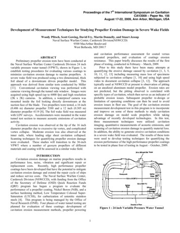
REMARK 1 The terms involving.the matrices 4,.A,, and A, in (3) capture the dependence of theaerodynamic forces on the displacement, velocity, andacceleration, respectively, of the wing mode shapes.The remaining term, involving the matrices D , R , andE on the right hand side of (3), account for the lag inaerodynamic forces./--. .34.5-25-20 -15-10-505Wing Span (ft)10152025Transforming (3) into the time domain andsubstituting the resulting expression into (1) and(2) yields the f
Structural Du rab i I i ty JEFFREY CAPLIN ASOK RAY, Senior Member, IEEE The Pennsylvania State University SURESH M. JOSM, Fellow, IEEE NASA Langley Research Center The concept and a design methodology for robust damage-mitigating control (DMC) of aircraft is presented. The