Transcription
Copyright by J.W. Zuyderduynwww.LearnSolidWorks.comPage 1
About LearnSolidWorks.comHi, my name is Jan-Willem Zuyderduyn and I live in theNetherlands. I am a Lead Product Designer and founder ofLearnSolidWorks.com.Since 2009 I help SolidWorkers to improve their SolidWorksmodeling skills by developing practical, step-by-stepSolidWorks tutorials.I am the author of dozens of SolidWorks eBooks and videos(125.000 downloads) and 4 premium SolidWorks self-studypackages all available on LearnSolidWorks.com.In these practical SolidWorks tutorial packages, I will showyou exactly how to model a stunning Aston Martin One-77sports car, an incredible American Chopper, an enormous108 ft. Superyacht and even an entire (76 meter!) longBoeing 747-8:http://learnsolidworks.com/pricingAre we already connected on social media? Click here to connect with me on LinkedInClick here to follow me on InstagramClick here to like my Facebook pageI encourage you to share this eBook with your colleagues and friends.Happy modeling!Jan-Willem ZuyderduynFounder LearnSolidWorks.comCopyright by J.W. Zuyderduynwww.LearnSolidWorks.comPage 2
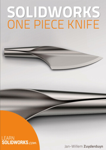
How to Model a One Piece Knife in SolidWorks?I recently saw a beautiful knife that was crafted out of one piece of twisting metal.It turned out to be the “One Piece Knife” designed by Johanna Gauder. This knife is madeout of a stainless steel sheet and its flowing form isn’t interrupted by an added handle.In today’s tutorial you will discover how to model this knife in SolidWorks yourself.Enjoy!Disclaimer: The intellectual property depicted in this 3D model, is not affiliated with or endorsed byJohanna Gauder. This 3D model may not be used for any commercial, promotional, advertising ormerchandising use.Copyright by J.W. Zuyderduynwww.LearnSolidWorks.comPage 3
Open a New Part with the model units set to millimetersGo to: File New PartSave the File with the following name: One Piece Knife.SLDPRTCreate a 2D Sketch on the Right PlaneSelect the Right Plane from the Features tree and click on the sketch iconGo to: Tools Sketch Entities CircleDraw a circle concentric to the originGo to: Tools Dimensions SmartClick on the circle and assign a diameter of 20mm, as shown in the image belowClick on the Close sketch iconCopyright by J.W. Zuyderduynto close the sketch area.www.LearnSolidWorks.comPage 4
Create a Surface ExtrudeGo to: Insert Surface Extrude Select the circle sketchGo to the Property manager Direction1Select Blind and click on the flip directionAssign an Extrude lengthAssign a Draft angleClick OKicon to reverse the surface extrude directionof 250mmof 3 degrees and check the Draft outward boxto complete the operation.Copyright by J.W. Zuyderduynwww.LearnSolidWorks.comPage 5
Create a 2D Sketch on the Front PlaneSelect the Front Plane from the Feature tree and click on the sketch iconGo to: Tools Sketch Entities LineDraw a horizontal and vertical line as shown in the image belowGo to: Tools Dimensions SmartHold the CTRL key and select the vertical line and the origin, then assign the length of 80mmCopyright by J.W. Zuyderduynwww.LearnSolidWorks.comPage 6
Use the Surface TrimGo to: Insert Surface Trim Select the purple section of the surface as shown in the image belowGo to the property manager and select Remove SelectionsLeave the other parameters as defaultClick OKto complete the operation.Create a 2D Sketch on the Top PlaneSelect the Top Plane from the Feature tree and click on the sketch iconClick on the Normal Toicon to switch the view directionGo to: Tools Sketch Entities SplineCopyright by J.W. Zuyderduynwww.LearnSolidWorks.comPage 7
Draw a spline without any midpoints as shown in the image belowHold the CTRL key, select the spline and the surface edge1Then, add a tangent relationbetween themAgain, hold the CTRL key, select the spline and surface edge2Then, assign another tangent relationGo to: Tools Dimensions SmartCopyright by J.W. Zuyderduynwww.LearnSolidWorks.comPage 8
Click on each spline handle and add handle values of 100mm and 300mm as shown in theimage belowUse the Surface TrimGo to: Insert Surface Trim Select the purple section of the surface as shown in the image belowCopyright by J.W. Zuyderduynwww.LearnSolidWorks.comPage 9
Go to the property manager and select Remove Selections and leave the other parametersas defaultClick OKto complete the operation.Create a 2D Sketch on the Front PlaneSelect the Front Plane from the Feature tree and click on the sketch iconGo to: Tools Sketch Entities SplineDraw a two point straight spline from the origin up to the next point, as shown in the imagebelowClick on the spline endpoints to activate the spline handlesHold the CTRL key, select the spline and the Surface EdgeThen, assign a tangent relationbetween themGo to: Tools Dimensions SmartCopyright by J.W. Zuyderduynwww.LearnSolidWorks.comPage 10
Click on each handle and assign the dimensions as showed in the image belowGo to: Tools Sketch Entities SplineAgain, draw a two point straight spline just under the origin up to the vertical surface edgeClick on the second spline and drag both end handles to activate themGo to: Tools Dimensions SmartCopyright by J.W. Zuyderduynwww.LearnSolidWorks.comPage 11
Click on each handle and assign the dimensions as showed in the image belowHold the CTRL key, select the two right endpoints of both splinesThen, assign a parallel relation between them, as shown in the image belowCopyright by J.W. Zuyderduynwww.LearnSolidWorks.comPage 12
Use the Surface TrimGo to: Insert Surface Trim Click on the purple surface between the two splines as shown in the image belowGo to the property manager and select Remove Selections and leave the other parametersas defaultClick OKto complete the operation.Create a 2D Sketch on the Top PlaneSelect the Top Plane from the Feature tree and click on the sketch iconClick on the Normal Toicon to rotate the view 180 degreesGo to: Tools Sketch Entities SplineCopyright by J.W. Zuyderduynwww.LearnSolidWorks.comPage 13
Draw a spline without midpoints as shown in the image belowMake sure that Point 1 and the Point 2 are coincident to eachother, as showed in the imageaboveClick on the spline and click on both spline handles to activate themGo to: Tools Dimensions SmartCopyright by J.W. Zuyderduynwww.LearnSolidWorks.comPage 14
Click on each handle and assign the dimensions as showed in the image belowUse the Surface TrimGo to: Insert Surface Trim Click on the purple surface section as shown in the image belowCopyright by J.W. Zuyderduynwww.LearnSolidWorks.comPage 15
Go to the property manager and select Remove Selections and leave the other parametersas defaultClick OKto complete the operation.Create a Reference Plane (Plane1)Go to: Insert Reference Geometry Plane Click on the horizontal surface edge (Edge 1 ) then click on the existing surface (Face 1 )The generated plane is highlighted in yellow as shown in the image belowClick OKto complete the operationCreate a 2D Sketch on Plane1Select Plane1 from the Feature tree and click on the sketch iconGo to: Tools Sketch Entities LineCreate a horizontal line and a vertical lineGo to: Tools Dimensions SmartCopyright by J.W. Zuyderduynwww.LearnSolidWorks.comPage 16
Assign the dimensions to both lines as showed in the image belowGo to: Tools Sketch Entities SplineCreate a two point spline as shown in the image belowGo to: Tools Dimensions SmartAdd dimensions to the spline as shown in the image belowCopyright by J.W. Zuyderduynwww.LearnSolidWorks.comPage 17
Use the Planar Surface featureGo to: Insert Surface Planar The current sketch (Sketch6) automatically gets selectedIn the modelling area a yellow enclosed flat surface is generated, as shown in the imagebelowClick OKto complete the operationCreate a 3D SketchSelect the Front Plane from the Feature tree and click on the sketch iconGo to: Insert 3D sketchGo to: Tools Sketch Entities Center Lineor click directly on Center LineCreate a vertical construction line with an angle of 15 degrees, as shown in the image belowCopyright by J.W. Zuyderduynwww.LearnSolidWorks.comPage 18
Go to: Tools Sketch Entities SplineDraw a spline between Point A and Point BHold the CTRL key, select the spline and the highlighted Curved EdgeCopyright by J.W. Zuyderduynwww.LearnSolidWorks.comPage 19
Add a tangent relationbetween them, as shown in the image belowHold the CTRL key, select the spline and the diagonal construction lineAssign a tangent relationbetween them, as shown in the image belowGo to: Tools Dimensions SmartCopyright by J.W. Zuyderduynwww.LearnSolidWorks.comPage 20
Assign the dimensions to the spline handles as showed in the image belowClick on Close sketchto close the sketch area.Create a 2D Sketch on the Front PlaneSelect the Front Plane from the Features tree and click on the sketch iconGo to: Tools Sketch Entities LineCreate a vertical line coincident to Point A as shown in the image belowCopyright by J.W. Zuyderduynwww.LearnSolidWorks.comPage 21
Use a Split LineGo to: Insert Curve Split LineGo to the property manger, Select Projection as a Type of SplitSelect the current sketch from the modelling areaThe selected sketch is shown as Current Sketch in the Sketch to Projectdialog boxThen, click on the curved surface (highlighted in blue) from the modelling area to split itThe selected surface is shown as Face 1 in the Face to SplitClick OKdialog boxto complete the operation.Use the Boundary SurfaceGo to: Insert Surface Boundary Surface Go to the property manager, click on the Direction1 boxCopyright by J.W. Zuyderduynwww.LearnSolidWorks.comPage 22
Move to the modelling area, click on Edge 1 and Edge 2, as shown in the image belowGo to the property manager, Click on the Direction2 boxMove to the modelling area, click on Edge 3 and 3D Sketch1, as shown in the image belowGo to the property manager, click on Edge 1 from the Direction 1 dialogue boxAssign the influence – Tangency to Face with Tangent Influence (%): 100Copyright by J.W. Zuyderduynwww.LearnSolidWorks.comPage 23
Click on the Edge 2 from the Direction 1 dialogue boxAssign the influence – Tangency to Face with Tangent Influence (%): 100Go down in Direction 2 dialogue box and click on the Edge 3 Assign the influence – Tangency to Face with Tangent Influence (%): 100Click on the 3D Sketch 1 from Direction 2 dialogue boxAssign the influence NoneClick OKto complete the operation.Use the Knit SurfaceGo to: Insert Surface Knit Select the three existing surfaces from the modelling areaGo to the property manager and check the merge entities box, as shown in the image belowClick OKto complete the operation.Copyright by J.W. Zuyderduynwww.LearnSolidWorks.comPage 24
Use the Thicken featureGo to: Insert Boss/ Base ThickenSelect the existing Knitted surface as Thicken parameterGo to the property manager, select the first iconAssign a thickness valueClick OKfrom the modelling areaas thickness typeof 1.5mm and check the Merge result optionto complete the operation.Make a ChamferGo to: Insert Features ChamferCopyright by J.W. Zuyderduynwww.LearnSolidWorks.comPage 25
Select the highlighted curved edge of the knife, as highlighted in yellow in the image belowGo to the property manager and select Angle distance from the chamfer parametersAssign the chamfer distanceof 1.5mm and the chamfer angleof 80 degreesLeave the other options as defaultClick OKto complete the operation.Add some FilletsGo to: Insert Features Fillet/RoundSelect the two tiny straight edges of the knifeCopyright by J.W. Zuyderduynwww.LearnSolidWorks.comPage 26
The selected edges are highlighted in yellow as shown in the image belowGo to the property manager and assign a Fillet radiusClick OKof 1mmto complete the operation.Add another FilletGo to: Insert Features Fillet/RoundRight click on the Fillet Edge 1Select Tangency from the pop up menu to select all the tangent edges.Similarly, right click on the Fillet Edge 2Select Tangency from the pop up menu to select all the tangent edges.If some edges are left, select them manuallyCopyright by J.W. Zuyderduynwww.LearnSolidWorks.comPage 27
All selected edges are highlighted in yellow, as shown in the image belowGo to the property manager and assign a Fillet radiusClick OKof 0.75mmto complete the operation.Use the Move/ Copy Body Tool – to Orient the KnifeGo to: Insert Features Move/ Copy Copyright by J.W. Zuyderduynwww.LearnSolidWorks.comPage 28
Select the knife from the modelling area, as shown in the image belowGo to the property manager and click on the RotateoptionAssign rotation values around X, Y and Z AxisX -95 degrees,Y 90 degrees, andZ 3 degreesLeave the translation values as defaultClick OKto complete the operation.Copyright by J.W. Zuyderduynwww.LearnSolidWorks.comPage 29
Change the AppearanceGo to: PhotoView 360 Edit Appearance Select Appearances (color) Metal Steel Polished SteelDouble click on the Polished Steel iconClick OKto apply the new appearanceGo to: View DisplaySelect Shaded, Shadows In Shaded ModeCopyright by J.W. Zuyderduyn, and Ambient Occlusionwww.LearnSolidWorks.com(If possible)Page 30
The whole Knife will look like as shown in the image belowSave the File againCongratulations, you just finished your own One Piece knife in SolidWorks!Copyright by J.W. Zuyderduynwww.LearnSolidWorks.comPage 31
Did you like this free eBook and are you eager to learn more? Then you should really attendmy free SolidWorks workshop.In this workshop, you are going to discover how to become a SolidWorks Pro in days insteadof years without boring practice, expensive training classes, or any pointless theory:Click here to attend my free SolidWorks workshop.In this free SolidWorks workshop you will discover: The 4 secret ways to learn SolidWorks and why you actually need to know what they areand which is best for you to be successful. The simple tricks that get people with no SolidWorks experience, no design or engineeringexperience, think they’re too old, and procrastinate too much to actually learn SolidWorks. The 6 secret career hacks to become highly successful as a designer or engineer to climbthe career ladder much faster. How I modeled a REAL 37.000.000 SuperYacht in SolidWorks for a famous Americanentrepreneur and how you can get similar design projects as well. Free access to the first eBooks and videos of the SolidWorks Chopper, Yacht, Aston Martin& Boeing 747 course!Click here to attend my free SolidWorks workshop.The entire workshop will take around 90 minutes so make sure to reserve enough time.So take a cup of coffee, grab a pen and paper and enjoy! Best wishes,Jan-Willem ZuyderduynCopyright by J.W. Zuyderduynwww.LearnSolidWorks.comPage 32
The selected surface is shown as . Face 1 in the . Face to Split . dialog box Click . OK . to complete the operation. Use the Boundary Surface Go to: Insert Surface oundary Surface Go to the property manager, click on the . Direction1. box . Split line tool in solidworks. Sketch selection in split line tool in solidworks. Faces to split .