Transcription
FAQ ON EARTHING STANDARDS16/08/2018This document has been updated to include changes made to substation earthing layouts thathave been made necessary due to copper theft. The main changes to be aware of are thegrading ring will be changed to 70mm2 bare copper coated steel conductor buried at a depthof 150mm below finished ground line. The grading ring will no longer be connected to the HVearth electrodes. Separate connections to the HV earth electrodes will be 70mm2 PVCinsulated copper conductor buried at a depth of 1200mm. Earthing connection single linediagrams for the different substation configurations are shown at the end of this document.Note that for the Modular Packaged Substation (MPS) only, 2 additional electrodes areconnected to the grading ring. These grading ring electrodes are to equalize touch potentials.They consist of a single 1.5m long earth stake and do not have a target earth resistance.Western Power will continue to specify prescribed values of earthing resistances in the shortterm but will be moving to risk based earthing in accordance with AS/NZS 7000:2016 and AS2067:2016 in the near future.FAQs1) What minimum readings do we have to get for:a) Standalone RMU – maximum 10 ohms per HV electrode where 2 HV electrodesexist per RMU.b) Standalone TX (up to 1,000kVA) – refer to table below for resistance per HVelectrode. When HV and LV earths are combined then final installation shall be nogreater than 1ohm.Pole top transformer not greater than 315 KVAPad-mount transformer rating up to 160 KVAPad-mount transformer rating 160 KVA and overmax 30 Ωmax 30 Ωmax 10 Ωc) Combined TX/RMU – maximum 10 ohms per HV electrode where 2 HV electrodesexist per TX/RMU site. When HV and LV earths are combined the final installationshall be no greater than 1 ohm.2) Do we drill additional rods at Pillars (UG network) or LV poles (OH network) to get tothe minimum combined earth reading of 1ohm?Yes, this can be done if 1ohm combined earthing cannot be met. This does not eliminatethe requirement of achieving the required earth resistances at each HV electrode of a TXor RMU site. It may be necessary to drill at pillars or LV poles where the LV network (ofnew subdivision) is sparse i.e. less than 20 pillars. Refer also to Q6.Where additional rods are drilled at a pillar to achieve 1ohm combined earthing, the pillarshall be marked “DEEP EARTH”. The label will be fitted inside the pillar, be nonconductive and be indelible. The deep earth will then form an integral part of the newinstallation and relocation of that pillar needs to account for the deep earth. The DeepEarth shall be marked on the ‘As Constructed’ drawing. A deep earth depth is typically30m.EDM# 28984244 (Published)EDM# 23131817 (Word)Page 1 of 12
3) Can we install counterpoise earthing, i.e. install an earth cable (bare or insulated)between the transformer site and another HV electrode further away from the site?No. The reason for this is earth potential rise can transfer voltages into adjacentequipment and/or services. Our preference is to use the cable screens (neutrals) that areinsulated and connect them to deep earths at pillars.4) Where does the minimum 10ohms per HV electrode for ground mounted equipmentcome from?a) The 10ohm is a standard industry resistance that is required to allow protection tooperate correctly.b) It has also been specified to ensure adequate surge protection operationc) Each HV electrode needs to be 10 ohm such that if the connection from 1 HVelectrode is broken (eg. for testing) or has been damaged the TX/RMU is stillconnected via the other 10ohm HV earth electrode, i.e. redundancy required as perAS/NZS 3000:2007, Section K.11.2.d) It is the level required (AS/NZS 3000:2007, Section K.11.5.2) for LV earthing for TX 500kVA when LV earths are separated from HV earths. Reasons are similar to (a).CMEN AreasEQUIPMENTLocal Earth AreaITEMRequirements CMENSeparately Earthed AreasHV EarthRequirementLV Earth RequirementAreaMENConnect allitems to 1 x 30 max local HVearth and areaCMEN.1 Separate Earth systemmax not usually employed.Requires approval fromEarthing Engineer priorto use.Separate Earth system notusually employed. Requiresapproval from EarthingEngineer prior to use.N/AGroundConnect allMounted URD items to 2 x 10 Substationmax local HVearths and areaCMEN.1 Separate Earth systemmax not usually employed.Requires approval fromEarthing Engineer priorto use.Separate Earth system notusually employed. Requiresapproval from EarthingEngineer prior to use.N/AHV SwitchPolesCountryN/A Connect all items to30 max local earthand running rmer-Connect allitems to 1 x30 max localHV earth andrunning earth.Less than 10 ohms (ground mount) or 30 ohms (pole mount) on each HV earthelectrode (rod)Less than 10 ohms combined on a stand alone RMU siteLess than 1 ohm combined including neutrals on a TX siteLess than 1 ohm combined including neutrals on a RMU & TX site.5) How many connections are required from the terminal bar and the HV earthelectrodes?Refer to the connection single line diagrams at the end of this document. The TerminalBar (defined in AS/NZS 3000:2007, Section K.11.4.4) of the transformer consists of 2parts that are interconnected i.e. LV bar and HV bar. The reason for having aninterconnection (Combined HV & LV link is factory fitted earth cable) is to allow forEDM# 28984244 (Published)EDM# 23131817 (Word)Page 2 of 12
separate HV and LV earthing if deemed absolutely necessary. With a single TerminalBar this would not be possible.There are 2 connections to the HV earth electrodes. Note that these no longer areconnected to the grading ring but are separate connections between the HV earth barand the HV electrode. Note also that for the Modular Packaged Substations (MPS) onlythere are two single 1.5m length earth electrodes connected to the grading ring for thepurpose of equalizing touch potentials.6) What are the steps and process to achieve earthing for a TX that complies with thestandards?There are two options for achieving electrode and system earthing resistancerequirements. One option is to install the earth equipment on site until the requirementsare achieved. The process for this is given in the table below. The other option is toengage an Earthing Consultant before the subdivision is installed to undertake an earthingdesign to determine the extent of earthing works required for the site that satisfies safetouch, step and transfer potential criteria. For both cases field measurements must be made toprove the network impedances.StepDescriptionResponsibility1Install (hammer or drill) HV earth rods at diagonal corners of groundmounted TX site or at the pole base for pole mounted TX. Each HVelectrode must have a maximum resistance of 10 ohms for groundmounted TX and 30 ohms for pole mounted TX. (Note that grading ringelectrodes consist of a single 1.5m long earth stake and do notDeveloper/installerhave a target earth resistance).Connect up all earths on new network. This includes transformer HV andLV earths and pillar earths and check combined earthing resistance. Theaim of the test is to achieve 1 ohm or less resistance.23Has 1ohm combined earthing been achieved?Yes – finished.No – go to next stepDrill deep eartha) At pillar furthest from the TX site for underground network.b) At pole at end of the LV circuit for overhead networkc) Check combined earth resistance does not exceed 1 ohm. Ifexceeded proceed to step 3Note: Drilling an earth at the furthest pillar or LV pole is to ensurethe earth is not within the zone of influence of the TX earth. Earthscan be installed within the zone of influence however they will not beas effective in reducing the overall earth mat resistance.Has 1ohm combined earthing been achieved?Yes – finished.No – go to next step.Combined earth exceeded for single remote drilled eartha) Drill at least 3 remote (2 additional) pillars or LV poles from thetransformer and each other to try to achieve the 1 ohmscombined earthing resistanceb) Where the 1 ohm combined earthing resistance is notachievable the maximum combined earth resistance permittedis 3 ohms before going to step 4Has 3 ohm combined earthing been achieved?Yes – # 28984244 (Published)EDM# 23131817 (Word)Page 3 of 12
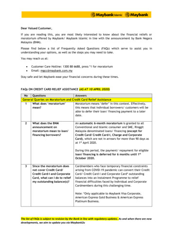
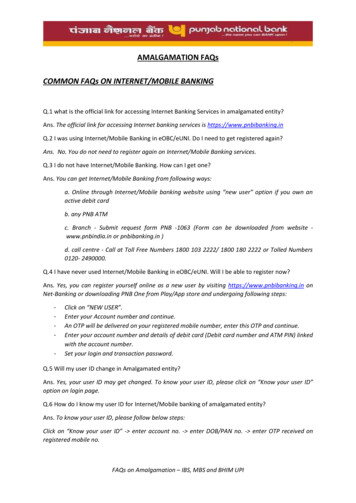
456.7.No – go to next stepInterconnect the new subdivision LV neutrals with the existing adjacentnetwork LV neutrals.Has 1ohm combined earthing been achieved?Yes – finished.No – go to next step.Suitably qualified engineer to conduct touch, step and transfer potentialcalculations to determine acceptability of installation.Note, separate earthing will only be considered when all the above hasnot achieved the desired EPR.Conform calculationsCopy of results and calculations must be forwarded to Western PowerDeveloper/EarthingConsultant7) What details do I need to submit to the Earthing Engineer, if at step 5?Details to include:a) Design Drawing of the siteb) Location, depth and earth resistance of HV electrodes installed (individually)c) Combined earth reading with HV and LV connected (i.e. HV electrodes, gradingring, HV and LV earth link all connected)d) Length of test leads used to measure the earth readings (i.e. length to P and Cprobe from the HV earth electrode)e) Indication of the first HV protection device upstream from the site. If TX only site,then the upstream fuse location and details. If RMU or RMU/TX site, then the firstupstream recloser or feeder circuit breaker.8) What length of earth test lead should be used to measure the electroderesistance?Most testers adopt the Fall-of-Potential method using a Current probe (C) and a Potentialprobe (P) that is placed 62% the distance of probe C from the earth electrode under test.When earth testing with Megger, if depth of the electrode is I, then the test probe P of theearth tester must be placed at minimum (or further) 2xI from the earth electrode and theC probe must be 3.2xI from the earth electrode (in that ratio where P probe is 62% thedistance between the earth electrode and C probe). This ensures an accurate earthresistance measurement, otherwise the measurement will result in higher resistancereadings due to summation of the zones of influence of the earth electrode and the Cprobe. Refer to arrangement below.EXAMPLE - if rods have been drilled to 10m (I) then probe P must be at a minimum (ormore) 20m (2 x I) from earth electrode and probe C must be 32m (3.2 x I) from earthelectrode.EDM# 28984244 (Published)EDM# 23131817 (Word)Probe PProbe CPage 4 of 12
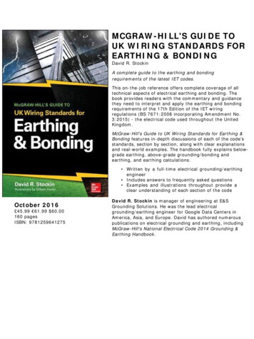
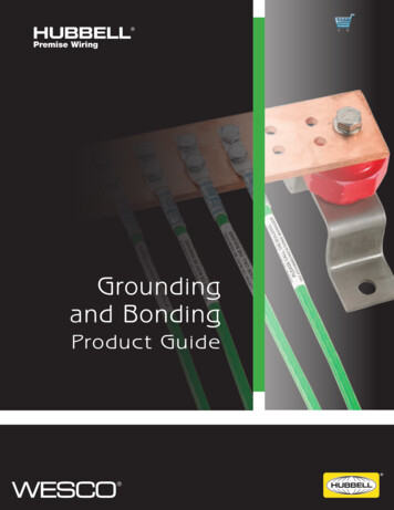
Below is a guide of test lead lengths required to test electrodes of various depths, whichshould be followed to achieve correct earth resistance readings. The test lead length isnot limited to 320m, where the test equipment is capable of longer lengths.ELECTRODE DEPTH 15m15 - 30m30 - 45m45 - 60m60 - 75m75 - 100mTest Lead lengths from Earth ElectrodePotential Probe (P)Current Probe (C)30m60m90m120m150m200m50m100m150m190m240m320m9) Are the earthing standards changing and how will this impact construction?Adherence to AS3000:2007 has been retained at present but will be superseded byAS2067:2016 in the near future. AS2067:2016 does not define resistance values to beachieved but instead defines touch voltage limits that are applied to a risk assessment.This means earthing systems need to be designed to meet the specific risk criteria for aparticular site and depends on:a) Earth fault current and durationb) Soil resistivityc) Level of LV interconnectiond) Other factors It is envisaged that each design drawing will have on it a resistance value that needs tobe achieved and any other remedial earthing work required to ensure touch voltage limitsare satisfied, all of which are derived by undertaking a level of earthing design. Standardresistance values of 30ohm, 10ohm and 1ohm may not exist.10) Do transformers need to have MEN connection if one is provided in the LVswitchboard?Yes, the transformer LV side must have a connection from LV neutral (either from neutralbushing or neutral bar) to the LV earth bar on the transformer. Similarly, an MEN isrequired in the Western Power LV distribution board which feeds the street or customers.The customer also needs to install an MEN at their installation in accordance withAS/NZ3000:2007. An MEN is required in the transformer because a separate earth cableis not connected between transformer earth bar and LV distribution board earth bar.MENConnectionMENLinkEDM# 28984244 (Published)EDM# 23131817 (Word)Page 5 of 12
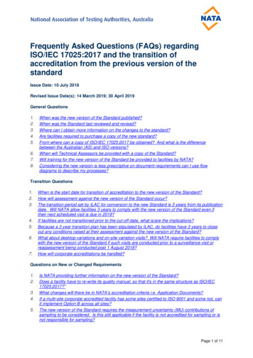
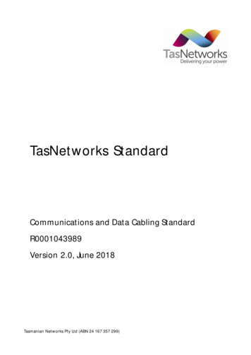
Ground-mount Substation Earthing Connection SingleLine DiagramsDrawing Notes:1. HV electrode connections are 70mm2 PVC insulated copper conductorburied 1200mm below finished ground level.2. Grading ring connections are 70mm2 copper coated steel conductorburied 150mm below finished ground level.EDM# 28984244 (Published)EDM# 23131817 (Word)Page 6 of 12
EDM# 28984244 (Published)EDM# 23131817 (Word)Page 7 of 12
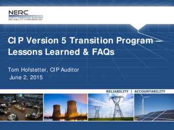
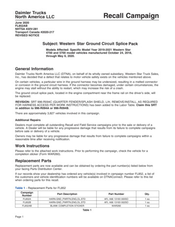
Note that the Modular Packaged Substation (MPS) requires 2 additionalelectrodes connected to the grading ring. These grading ring electrodes consistof a single 1.5m long earth stake and do not have a target earth resistance.EDM# 28984244 (Published)EDM# 23131817 (Word)Page 8 of 12
Note that the Modular Packaged Substation (MPS) requires 2 additional electrodes connected to the grading ring. These grading ringelectrodes consist of a single 1.5m long earth stake and do not have a target earth resistanceEDM# 28984244 (Published)EDM# 23131817 (Word)Page 9 of 12
EDM# 28984244 (Published)EDM# 23131817 (Word)Page 10 of 12
EDM# 28984244 (Published)EDM# 23131817 (Word)Page 11 of 12
EDM# 28984244 (Published)EDM# 23131817 (Word)Page 12 of 12
AS/NZS 3000:2007, Section K.11.2. d) It is the level required (AS/NZS 3000:2007, Section K.11.5.2) for LV earthing for TX 500kVA when LV earths are separated f