Transcription
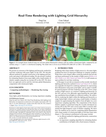
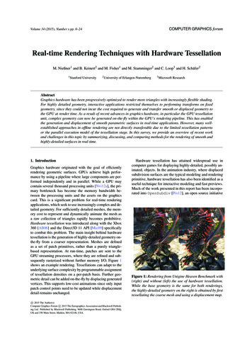
COMPUTER GRAPHICS forumVolume 34 (2015), Number x pp. 0–24Real-time Rendering Techniques with Hardware TessellationM. Nießner1 and B. Keinert2 and M. Fisher1 and M. Stamminger2 and C. Loop3 and H. Schäfer21 StanfordUniversity2 Universityof Erlangen-Nuremberg3 MicrosoftResearchAbstractGraphics hardware has been progressively optimized to render more triangles with increasingly flexible shading.For highly detailed geometry, interactive applications restricted themselves to performing transforms on fixedgeometry, since they could not incur the cost required to generate and transfer smooth or displaced geometry tothe GPU at render time. As a result of recent advances in graphics hardware, in particular the GPU tessellationunit, complex geometry can now be generated on-the-fly within the GPU’s rendering pipeline. This has enabledthe generation and displacement of smooth parametric surfaces in real-time applications. However, many wellestablished approaches in offline rendering are not directly transferable due to the limited tessellation patternsor the parallel execution model of the tessellation stage. In this survey, we provide an overview of recent workand challenges in this topic by summarizing, discussing, and comparing methods for the rendering of smooth andhighly-detailed surfaces in real-time.1. IntroductionGraphics hardware originated with the goal of efficientlyrendering geometric surfaces. GPUs achieve high performance by using a pipeline where large components are performed independently and in parallel. While a GPU maycontain several thousand processing units [Nvi12a], the primary bottleneck has become the memory bandwidth between the processing units and the assets on the graphicscard. This is a significant problem for real-time renderingapplications, which seek to use increasingly complex and detailed geometry. For sufficiently detailed meshes, the memory cost to represent and dynamically animate the mesh asa raw collection of triangles rapidly becomes prohibitive.Hardware tessellation was introduced along with the Xbox360 [AB06] and the Direct3D 11 API [Mic09] specificallyto combat this problem. The main insight behind hardwaretessellation is the generation of highly-detailed geometry onthe-fly from a coarser representation. Meshes are definedas a set of patch primitives, rather than a purely trianglebased representation. At run-time, patches are sent to theGPU streaming processors, where they are refined and subsequently rasterized without further memory I/O; Figure 1shows an example rendering. Tessellations can adapt to theunderlying surface complexity by programmable assignmentof tessellation densities on a per-patch basis. Further geometric detail can be added on-the-fly by displacing generatedvertices. This supports low-cost animations since only inputpatch control points need to be updated while displacementdetail remains unchanged.c 2015 The Author(s)⃝c 2015 The Eurographics Association and Blackwell PublishComputer Graphics Forum ⃝ing Ltd. Published by Blackwell Publishing, 9600 Garsington Road, Oxford OX4 2DQ,UK and 350 Main Street, Malden, MA 02148, USA.Hardware tessellation has attained widespread use incomputer games for displaying highly-detailed, possibly animated, objects. In the animation industry, where displacedsubdivision surfaces are the typical modeling and renderingprimitive, hardware tessellation has also been identified as auseful technique for interactive modeling and fast previews.Much of the work presented in this report has been incorporated into OpenSubdiv [Pix12], an open source initiativeFigure 1: Rendering from Unigine Heaven Benchmark with(right) and without (left) the use of hardware tessellation.While the base geometry is the same for both renderings,the highly-detailed geometry on the right is obtained by firsttessellating the coarse mesh and using a displacement map.
M. Nießner & B. Keinert & M. Fisher & M. Stamminger & C. Loop & H. Schäfer / Survey on Hardware Tessellationdriven by Pixar Animation Studios, for use in games and authoring tools. In the near future, hardware tessellation willalso be available on mobile devices [Nvi13, Qua13], opening the door for new applications in mobile graphics.Although tessellation is a fundamental and wellresearched problem in computer graphics, the availabilityof fast hardware tessellation has inspired researchers to develop techniques specifically crafted for hardware tessellation. This includes higher-order surface rendering methodsthat focus on different patch-based representations for thetessellator. Significant effort has been devoted to both accurately and approximately rendering subdivision surfaces.Hardware tessellation is also ideally suited for displacement mapping, where high-frequency geometric detail is efficiently encoded as image data and applied as surface offsets at run-time. Several approaches for incorporating suchhigh-frequency details on top of smooth surfaces have beendeveloped including methods for data storage, displacementevaluation, and smooth level-of-detail schemes. Additionalresearch focuses on improving performance by avoiding therendering of hidden patches; i.e., back-patch and occlusionculling. Further techniques address the handling of patchbased physics interactions such as collision detection forreal-time rendering.In this survey, we contribute a summary of such methodsthat are specifically designed for the GPU hardware tessellator and outline their contributions. In addition, we analyzeand compare these approaches with respect to their usabilityand practicality for different scenarios. Note that this surveyis the extended journal version of [SNK 14].The techniques to be covered involve solutions for smooth surface rendering,low-cost animations and surface updates,adaptive level-of-detail,high-frequency detail; i.e., displacements,compact, consistent, and efficient texture storage,dynamic memory management for textures,fine-scale mesh deformations,culling techniques for faster rendering,tessellation-based collision detection.Prior Hardware Tessellation Work Dynamic CPU-basedtessellation methods are difficult to apply to real-time rendering, as the tessellated meshes must be transferred to theGPU continuously. As GPUs became more programmable,tessellation started being performed directly on the GPU,avoiding costly CPU-GPU data transfers. Vertex shadersmade it possible to reposition vertices, so that the evaluation of vertex positions could be moved to the GPU, as longas a direct evaluation of the surface at a particular parameterposition is possible. Geometry shaders can perform simpletessellation; however, they usually slow down the pipelinesignificantly, particularly if a single shader outputs a largenumber of triangles.c 2015 The Author(s)⃝c 2015 The Eurographics Association and Blackwell Publishing Ltd.⃝Boubekeur et al. [BS05,BS08] proposed the use of instantiation for tessellation. In their method, simple triangles aretessellated according to a set of tessellation factors, and arekept in GPU memory as so-called tessellation patterns. Thetessellation patterns are then rendered using instantiation andapplied to the patches of the base mesh. The requirement tokeep patterns for all used tessellation factors results in a limited number of tessellation levels.Later, methods to adaptively generate tessellation usingGPGPU methods were presented. The hierarchical subdivision process is typically mapped to a parallel breadth-firsttraversal that successively generates smaller patches untilthey are considered to be fine enough [EML09, PEO09].Schwarz et al. [SS09] parallelize the process patch-wise using a single thread per patch. This allowed them to use moreefficient evaluation methods based on finite differences, butparallelization could only be exploited if a large number ofsingle patches were subdivided and the subdivision levelsdid not vary largely. Other GPGPU-based approaches consider contour and silhouette information to perform adaptive mesh refinement while avoiding tessellation disparities[BA08], [FFB 09].2. GPU Hardware Tessellation2.1. Graphics ArchitecturesModern GPUs are composed of several streaming multiprocessors (SMs) each of which is a vector processing unit.SMs process data chunks in parallel in a single-instructionmultiple-data (SIMD) fashion. The specific implementationof this kind of architecture is vendor-dependent. For example, NVIDIAs Kepler GK110 architecture [Nvi12b] consistsof 15 streaming multiprocessors of which each unit features192 single-precision cores resulting in a total number of2880 cores. In this architecture, threads are dispatched bythe streaming multiprocessors’ schedulers in groups of 32parallel threads called warps.In contrast to conventional CPUs, GPUs spend more diearea on computational units rather than on caches. Whilethere is a small amount of shared memory available per SM(64 KB for the GK110) which can be used as L1 cache, mostdata must be obtained from global GPU memory. Access toglobal memory is costly, as it introduces high latency. Typically, latency is partially hidden by running a sufficient number of threads simultaneously and issuing computational instructions without requiring any memory accesses.2.2. Graphics Pipeline and Hardware TessellationThe typical graphics pipeline on current GPUs consists offive programmable shader stages (see Figure 2). GPUs canbe programmed for rendering using the OpenGL or Direct3D API. Hardware tessellation has been accessible sinceDirect3D 11 [Mic09] and OpenGL Version 4.0 [SA12]. Inthe following, we will use the Direct3D nomenclature.
M. Nießner & B. Keinert & M. Fisher & M. Stamminger & C. Loop & H. Schäfer / Survey on Hardware TessellationVertex ShaderHull ShaderTessellatorDomain ShaderGeometry ShaderPixel ĞprogrammableprogrammableprogrammablePer input vertexPer patch controlpointSet domain locaƟonsand topologyPer domain locaƟŽŶPer (generated)trianglePer fragmentFigure 2: Graphics pipeline according to Direct3D 11 nomenclature involving programmable shader and configurable hardware stages. For simplicity, the fixed-function stages input assembly, rasterization and output merger are omitted.Highly-tessellated meshes result in large memory footprints in GPU memory and are costly to render. In contrast,hardware tessellation allows for more output polygons sinceglobal memory access is only required for a sparse set of input control points. We benchmark this by generating 2 million output polygons on a planar grid using an NVIDIA GTX780 graphics card. While conventional rendering using index and vertex buffers takes about 1.5 ms, using hardwaretessellation takes only 0.25 ms; i.e., more efficient by a factor of 6. However, enabling hardware tessellation withoutfurther tessellation of input patches is ineffective. That is,rendering the 2 million triangles with the tessellation unitand treating every triangle as a separate patch primitive witha tessellation factor of 1 is 5 times slower. Therefore, hardware tessellation should only be used where required; i.e.,when the application necessitates further patch tessellation.Hardware tessellation elevates patch primitives to first classobjects in the graphics pipeline. These patches are each defined by a set of control points, and processed in parallel bythe GPU. The tessellation unit generates parameter samplevalues within corresponding patch domains where patchesare evaluated. Currently, triangular, quadrilateral, and isolinedomains are supported. Based on the tessellation configuration, patches are evaluated at the sample locations in order to generate an output stream composed of triangles. Thekey advantage is that these polygons are directly processedby the GPU streaming processors without involving furtherglobal memory access needed for vertex geometry data, thusminimizing memory I/O. This enables high-performance,dynamic patch tessellation.Hardware tessellation introduces three new pipelinestages between vertex and geometry shading (see Figure 2):the hull shader stage, the tessellator stage and the domainshader stage. The hull shader stage is divided into two logical parts: a per-patch constant function and the actual hullshader program. The per-patch constant function is executedonce per input patch and is used to determine the patch tessellation density. As such, per-patch tessellation factors arecomputed and sent to the fixed-function tessellator stage inorder to specify the amount of generated domain samplepoints. For tri- and quad-domains there are edge (3 for tris,4 for quads) and interior (1 for tris, 2 for quads) tessellationfactors. The isoline domain is only controlled by two edgetessellation factors that determine the line density and theline detail. Aside from integer tessellation factors, fractionaltessellation factors are also available, enabling smooth levelof-detail transitions. The hull shader program is executed forevery patch control point. While one thread processes a single (output) control point, all patch input point data is sharedamong hull shader programs of the same patch. Currently,the number of control points is limited to 32 per patch.The hull shader stage is followed by the fixed-functiontessellator, generating sample points and topology for agiven patch domain based on input tessellation factors. Examples of resulting tessellation patterns are shown in Figure3, including tri- and quad-domains, as well as integer andfractional tessellation factors.The last stage of the tessellation pipeline is the programmable domain shader stage where a shader program isinvoked for each sample location. The input for this stageis composed of the hull shader output (i.e., tessellation factors, control points) and domain sample parameters. Theseare either barycentric coordinate triples uvw (tri-domain), ortwo-dimensional uv coordinates (quad and isoline domains).Based on the input, patches are evaluated, and an outputvertex is generated for every domain sample. In addition,per-vertex attributes such as texture coordinates and surfacesnormals must be computed and passed along with the posi-5.04255.4246.66Figure 3: Generated tessellation patterns of triangle andquad patch domains for different tessellation factors. Left:patches are uniformly tessellated in the interior (white) andsupport arbitrary tess factors on the edges resulting in transitional triangulation (colored) for watertight rendering ofadjacent patches with different interior factors. Right: fractional tessellation enables smooth transitions between integer levels (fractional triangles red).c 2015 The Author(s)⃝c 2015 The Eurographics Association and Blackwell Publishing Ltd.⃝
M. Nießner & B. Keinert & M. Fisher & M. Stamminger & C. Loop & H. Schäfer / Survey on Hardware Tessellationtions of emitted vertices. These vertices are then triangulatedusing the topology generated by the fixed function tessellator and processed by the remaining stages of the graphicspipeline.Fortunately, it is relatively easy to evaluate the Bernsteinbasis in a reversal invariant way; i.e., independent of parameter direction. This can be achieved using the followingprocedure3. Higher-Order Surface Renderingvoid EvalBezCubic(float u, out float B[4]) {float T u, S 1.0 - u;One of the main purposes of hardware tessellation is to support higher-order surface primitives, particularly parametric patches. A parametric patch is a mapping from a unitsquare or triangle (parameter) domain into 3D space. Theprecise nature of this mapping is specified by the programmer, both in terms of the assigned meaning of the input data,and the evaluation procedures executed by the hull and domain shader programs.3.1. Bézier PatchesWe start with a tensor product bi-cubic Bézier patch, written3P(u, v) 3 bi, j B3i (u)B3j (v),(1)B[0]B[1]B[2]B[3] S*S*S;3.0*T*S*T;3.0*S*T*S;T*T*T;}Note that replacing u by 1 u interchanges the values ofS and T, leading to the reversal of basis function values. Theboundary curve is evaluated by taking the dot product of the4 boundary control points and these basis function values.Guaranteeing that the results are bitwise-identical on bothsides of a shared boundary requires commutativity of bothaddition and multiplication. These commutativity requirements are satisfied by using IEEE floating point strictnesswhen compiling shader programs.i 0 j 0where u, v are the coordinates of a point in a unit squaredomain [0, 1] [0, 1], bi, j are 16 three-dimensional controlpoints that determine the shape of the patch, and B3k (t) areBernstein polynomials that are defined as( )d(1 t)d k t k .(2)Bdk (t) kThe 16 patch control points are transmitted to the GPU ina vertex buffer (either contiguously, or referenced by an index buffer). A hull shader program is executed once for eachoutput vertex (in parallel).3.1.1. Crack AvoidanceBézier patches have the property that the 4 patch controlpoints along the shared edges between pairs of patches mustbe identical to maintain a continuous, C0 surface. In orderto avoid cracks in a rendered surface, adjacent patches mustbe C0 . Furthermore, the tessellation factor must be assignedidentically to the shared edge between a pair of adjacentpatches; otherwise, the tessellation unit may not sample theshared patch boundary at corresponding parameter valuesof adjacent patches, leading to cracks. Sharing control pointdata and assigning identical tessellation factors along sharededges is necessary to avoid cracks, but it is not sufficient.Additionally, the domain shader program must take into account the different ordering of the control points with respectto the two patches sharing an edge. If it does not, then different numerical roundings may accumulate sufficiently tocause output vertices to project to different pixels, resulting in visible cracks between patches. The degree to whichthis matters is application dependent, but in many cases suchcracks must be avoided to guarantee a high rendering quality.c 2015 The Author(s)⃝c 2015 The Eurographics Association and Blackwell Publishing Ltd.⃝While guaranteeing bitwise-identical geometry alongshared patch boundaries is fairly straightforward usingBézier patches, guaranteeing bitwise-identical normals isnot. The problem is that cross-boundary derivatives (e.g., thev direction, if u is along the boundary) may not be computedidentically since they are constructed from different (nonshared) input data. This will result in slightly different normal vectors along a shared patch boundary. When used forlighting, the small color differences that might result may notbe a problem. However, when used for displacement mapping, these differences will likely lead to visible cracks alongpatch boundaries. These problems are much easier to avoidby using the B-spline basis.3.2. B-spline PatchesThe B-spline basis has deep theoretical roots far beyond thescope of this report; we give B-splines only superficial treatment here. B-splines are a special case of the more generalNon-Uniform Rational B-splines (NURBS), that are uniformand polynomial (non-rational).A bi-cubic B-spline surface can be written as a piecewisemapping from a planar domain [0, m 1] [0, n 1]mP(u, v) n di, j N 3 (u i)N 3 (v j),(3)i 0 j 0where the di, j are a rectangular array of B-spline controlpoints, and N 3 (t) is a cubic B-spline basis function. N 3 (t) isa C2 smooth, piecewise cubic polynomial curve comprisedof 4 non-zero curve segments. Since these basis functionsare C2 (curvature continuous), a linear combination of themis also C2 . This makes the construction of a curvature continuous surface easy.
M. Nießner & B. Keinert & M. Fisher & M. Stamminger & C. Loop & H. Schäfer / Survey on Hardware TessellationEach individual cubic curve segment is determined by 4contiguous control points, and each bi-cubic B-spline patchby 16 control points. A pair of adjacent curve segments willhave 3 control points in common. Similarly, a pair of adjacent patches will have 12 control points in common. These12 shared control points are exactly the ones needed to construct the positions and normals along the shared boundary.3.3. Catmull-Clark Subdivision SurfacesCatmull-Clark subdivision [CC78] is a generalization of bicubic B-spline subdivision to irregular control meshes. Thatis, a mesh with faces and vertices not incident on 4 edges (extraordinary vertices). By repeating the subdivision process,a smooth limit surface is obtained as shown in Figure 4.Figure 4: Several iterations of Catmull-Clark subdivisionapplied to a cube-shaped base mesh.The algorithm is defined by a simple set of subdivisionrules, which are used to create new face points ( f j ), edgepoints (e j ) and vertex points (v j ) as a weighted average ofpoints of the previous level mesh.structure of the surface that is known once an individual Bspline patch has been determined. This patch structure is illustrated in Figure 7. We will see in Section 3.7 that thisstructure can be exploited using hardware tessellation for efficient rendering of the Catmull-Clark limit surface.While subdivision surfaces freed designers from thetopology constraints of B-splines, further development wasneeded to make them truly useful. For instance, the original subdivision rules did not consider the case of a meshwith boundary. Subsequent work took the idea a step furtherand allowed edges to have a variable amount of sharpness –called creases [HDD 94, DKT98].3.4. Parallel Subdivision using GPU KernelsAs shown before, the rules for constructing new mesh pointsinvolve taking weighted averages of small, local collections of old mesh points. Gathering these points on theCPU usually involves neighborhood queries using a meshconnectivity data structure; e.g., winged-edge, half-edge, orquad-edge. While the details between these structures differ slightly, the basic idea is the same. Incidence relationsare captured by linking edge data with pointers. In order tosatisfy a neighborhood query (e.g., given a vertex, return allthe vertices sharing an edge with the vertex in order), theconnectivity structure must be traversed, one edge at a time,by following links and dereferencing pointers. Doing this onthe GPU is impractical, due to the length and varying sizesof these edge chains.3.3.1. Subdivision Rules3.4.1. Subdivision TablesThe Catmull-Clark smooth subdivision rules for face, edge,and vertex points, as labeled in Figure 5, are defined as:By assuming that mesh connectivity is static, or at least doesnot change often, a simple table-driven approach becomesfeasible [NLMD12]. The idea is to encode the gather patterns of vertex indices, needed to construct new mesh pointsfrom old mesh points, and store these in tables. Since thereare 3 types of new points being constructed in a CatmullClark subdivision surface (face, vertex, and edge), 3 compute kernels are used. Each compute kernel executes a single thread per new mesh point, and uses the indices storedin the tables to gather the old mesh vertices needed in theweighted average. Note that variations of table-driven subdivision have been used before general purposed computingwas available on the GPU (e.g., [BS02]). Faces rule: f i 1 is the centroid of a face’s vertices.i 1i 11 ii Edge rule: ei 1j 4 (v e j f j 1 f j ), Vertex rule: vi 1 1n 2 in v n2 eij n12 f ji 1 .jjv0f 1nf 12v1e 11f 11e 01e 03e 13e 0ne 12e 02Figure 5: Labeling of vertices of a Catmull-Clark [CC78]base mesh around the vertex v0 of valence n.In the case that the input control mesh is locally regular, the resulting surface will locally be a bi-cubic B-spline.Additional refinements over these regions, while needed torefine the mesh, are not needed to determine the polynomial3.4.2. GPU Subdivision versus Hardware TessellationGiven that subdivision on the GPU can be performed usingtables, it may seem that patch-based hardware tessellationis not needed for rendering these primitives. One can simply transfer an unrestricted control cage to the GPU and letits massive data-parallelism generate and render millions oftriangles. The problem with this idea is GPU memory bandwidth. Each level of the refined mesh must be streamed toand from the GPU and off-chip GPU memory. Each newlygenerated level is roughly 4 times as large as the old level;c 2015 The Author(s)⃝c 2015 The Eurographics Association and Blackwell Publishing Ltd.⃝
M. Nießner & B. Keinert & M. Fisher & M. Stamminger & C. Loop & H. Schäfer / Survey on Hardware Tessellationi.e., an exponential growth rate. While the table-driven approach efficiently maps the subdivision rules to the GPU,naïve use of this method will quickly become I/O bound.Hardware tessellation, on the other hand, is incredibly efficient since it avoids global (off-chip) memory accesses.Once a compact patch description is streamed to a local GPUcache, no further global memory accesses are needed. Thehull, tessellation, domain, and even rasterization stages areall performed using fast, local GPU cache memory.3.5. Stam’s AlgorithmStam [Sta98] proposed a method for the exact evaluationof Catmull-Clark Subdivision Surfaces. The advantage ofStam’s algorithm is that it treats a subdivision surface as aparametric surface, which is seemingly ideal for hardwaretessellation. In order to make the combinatorics tractable,Stam’s algorithm requires that extraordinary vertices be isolated, so that no quadrilateral face is incident on more thanone extraordinary. A face incident to a single extraordinaryvertex, together with the vertices of all incident faces, is theinput to Stam’s algorithm; see Figure 6a. Let this collectionof 2n 8 vertices be labeled v0 . With the resulting parameterization, all sub-patches can be enumeratedFj,k (u, v) N 3 (u)N 3 (v) · Pj · Sk · v0 ,(4)where j 1, 2, 3 is the index of a quad sub-domain (see Figure 6b), k is the level of subdivision, N 3 (t) is the cubic Bspline basis function, Pj is a picking matrix that generates thecorresponding B-spline control points for the chosen patch,and S is the subdivision matrix whose entries correspond tothe weights of the Catmull-Clark subdivision algorithm; forthe details, we refer to [Sta98]. Performing the eigen decomposition of S, the patches are rewritten asFj,k (u, v) N(u, v) · Pj ·V · Λk · V 1 · v0 , {z } {z}eigen basisfunctions(5)eigen spaceprojectionwhere V and V 1 are the left and right eigenvectors and Λis the diagonal matrix of eigenvalues of S. Writing Fj,k (u, v)this way shows that subdivision, or taking the matrix S to thekth power, can be replaced by raising the diagonal elementsof Λ to the kth power. This requires substantially less computation, O(c) operations per parametric evaluation. However, the constant c is rather large, due to the large number of floating point operations needed to evaluate the eigenbasis functions and their derivatives. Further, Stam’s algorithm does not handle sharp subdivision rules, and obtainingbitwise-exact boundary evaluation of positions and normalsis problematic due to the eigen space projection.3.6. Approximate Subdivision MethodsIn order to maximize performance, researchers consideredways to render smooth higher-order surfaces that behavesimilarly to subdivision surfaces but are easier to evaluate.c 2015 The Author(s)⃝c 2015 The Eurographics Association and Blackwell Publishing Ltd.⃝0,132010,0a)1,0b)c)Figure 6: a) Collection of control points input into Stam’salgorithm. b) Labeling of corresponding sub-domains. c)Nesting of sub-domains around an extraordinary vertex.3.6.1. PN-trianglesThe PN-triangle technique [VPBM01] was developed to addgeometric fidelity to the large body of existing triangle meshmodels. For each triangular face, a cubic Bézier trianglepatch is constructed using only the position and normal dataof the three incident vertices. A cubic Bézier triangle is determined by 10 control points. The position and normal ateach vertex determines 3 control points that span the corresponding tangent planes. The final control is determinedby a quadratic precision constraint; that is, if the 9 previously constructed control points happen to be consistent witha quadratic, then this 10th control point will be consistentwith the same quadratic. Note that this construction guarantees that a PN-triangle surface is continuous (C0 ), but notsmooth (C1 ). To overcome this shortcoming, a PN-trianglecontains a quadratic normal patch, whose coefficients arederived from the triangle’s vertex normals. These normalpatches, which are also continuous, are used for shadingrather than the cubic geometry patch.PN-triangles predate hardware tessellation, but their relatively simple and local construction is well suited to thehardware tessellation paradigm. A hull shader program canbe used to convert a single mesh triangle and associated vertex data into a cubic geometry, and quadratic normal, patchpair. The domain shader stage will evaluate the cubic andquadratic input patches at their barycentric uvw coordinatetriples. While PN-triangles are effective at improving the appearance of traditional triangle mesh models, they are not thebest choice for obtaining results that approach the geometricquality of subdivision surfaces.3.6.2. ACC-1: Approximation using Bézier PatchesSubdivision surfaces can be approximated based on quadrilateral bi-cubic patches [LS08]. Given a quad mesh as input,the idea is similar to PN-triangles in that a geometry patchis constructed to interpolate the position and tangent planeof the Catmull-Clark subdivision limit surface at the corners of a mesh quadrilateral. This bi-cubic patch, while designed to approximate the Catmull-Clark limit surface, willonly be continuous, not smooth. Therefore, a normal patchis generated to create a smooth normal field for shading. Aswith PN-triangles, this algorithm is easily implemented in
M. Nießner & B. Keinert & M. Fisher & M. Stamminger & C. Loop & H. Schäfer / Survey on Hardwa
Volume 34 (2015), Number x pp. 0–24 COMPUTER GRAPHICS forum Real-time Rendering Techniques with Hardware Tessellation M. Nießner1 and B. Keinert2 and M. Fisher1 and M. Stamminger2 and C. Loop3 and H. Schäfer2 1Stanford University 2University of Erlangen-Nuremberg 3Microsoft Res